Jerry Isdale
-
Log 7: Spring 2023 Developments
06/24/2023 at 11:34 • 0 commentsQuick project log to note Spring 2023 developments.
After a bit delving into Google Coral (Log 6), I went back to the PC side for a bit to get some basic demos running in TouchDsigner (let alone Unity or Unreal). The Pose2Art GitHub repo now has a bunch of prototypes, and an updated capture-osc gui tool.
- PosePCGui.py : Tk ui that lets us select videos (looping) or webcam as input, does capture and forwards OSC and NDI video out. Looped Video is very useful for feeding TD (etc) tools during development. I found several decent dance videos and cropped to short segments.
(Note: somewhere in between Feb and June OpenCV.CaptureVideo stopped working. In June I got read errors that MSMF layer could not access the webcam. It worked back in Feb?? simple CameraTest.py created and found need to use DSHOW flag - old direct show api)
A few TD networks have been created to explore options there. For Example (in github repo):
- handDrawing.toe - move a light-ball on hand-tip
- handDrawing_wNDI.toe - move a light-ball on hand-tip, pass NDI video out
- landmarksAsSpheres.toe - puts a sphere at each landmark (incl face?)
- landmarksAsGeom_wNDI.toe - similar to sphere, also rcvs video via NDI
- handsAsEmitters.toe - particle emitters at hand tips (vid save to file)
- OSC_TubularTrim.toe - make flat/tube skeleton between landmarks
- osc_fluidHand.toe - beginnings of putting a fluid emitter on hands
More experiments being done in non-git test subfolder - digging into fluidSim, particles, alternative Skeleton-Pose tools that do 3d and-or crowds etc. TD network layout has evolved through the development of those prototypes, with possible style developing that might encapsulate in a tox module.
Also looking into parallel tool to do hand/gesture recognition and share hand skeleton + Gestures via OSC. There are a number of good (recent) examples of ML webcam for hands, and how to train your own Gestures layer over basic skeleton. A Hand Tracking/Gesture camera might be used as a 2nd input, allowing webcam control of an installation. (have a kiosk with webcam above a good ?horizontal? background surface?)
Building the TD prototypes showed some needs for the smart cam side - passing video thru via NDI being big one. Also created a pose_detector module that encapsulates the basic flow, with options for different recognition engines - MediaPipe currently implemented, AlphaPose stubbed (crowd recog?!)
Learned a bit more about ML models and will need to revise that part of the project to reflect the process, including pointers on training custom recognizers - particular to installation.
-
Log 6: Hiatus Interuptus - Google Coral Arrived
02/02/2023 at 02:01 • 0 commentsThis project has been on hiatus (hold) for a couple months after I got severely disappointed with the Raspberry Pi 4 speed. That and needing to find some better TouchDesigner examples with Skeleton. I found several of the later as well as inspiration from the interactiveimmersive.io folks, especially since signing up for their HQPro training. I'll get to those in another update.
The BIG NEWS is the Google Coral Dev Board is back in stock at a few vendors (amazon and adafruit for 2). I snagged one and just got it running. Unfortunately the Coral Camera is not in stock and the connections are different enough from the RaspberryPi cameras that they are incompatible. My older usb webcam also failed to be recognized by the coral. Fortunately, I found my Creative VF810 depth camera - same as the IntelRealSense SR300. Unfortunately, these are no longer supported by Creative or Intel. Fortunately, it still worked just fine with the Coral as video1 !! So far I've only run thru the Demos in their Getting Started, but I have high hopes for getting it working with the OSC code.
I did also note that the SR300 shows up as 2 cameras. The video2 camera appears to be the depth camera and I'll have to explore that more.
Not sure when i'll get updates here as life continues to keep me busy with other distractions (2 acres of rainforest/field in Haiku HI, etc) but please check in!
-
Log 5: It Works! Sorta. Now What? Phase2?
12/18/2022 at 18:17 • 0 commentsDec 2022 - Ok it works but only sorta. The Raspberry Pi 4 is giving us 8-10frames per second. That isnt good enough for interaction. The initial TouchDesigner patch (Cronin4392) works but alas is not good demo on which to build. I still think the basic idea is good: a mostly open source platform to use rapidly evolving AI (ML/DL) Pose tools with powerful interactive generators (TouchDesigner, Unity, Unreal, etc). So what do we do to continue Pose2Art?
Here are some threads I plan to explore to make it better:
- Quick Overview Video
Project documentation like this does a LOT better with a short introductory video. I am working on a better physical setup to shoot the video as well as climbing the learning cliff on a video editing tool
- Replace rPi4:
The pi is cool and all but it does not have the processing power to handle the AI (neural net) processing at interactive rates. There are alternatives. Google Coral? RockPi? PC w/older RTX board? I have an Nvidia Jetson Nano Dev Board. It benchmarks better than rPi but is being retired by Nvidia in favor of newer faster boards. However, I have one, and Qengineering has an OS build similar to the Pi one we used already. Code should port fairly easy. Lets give it a try.
- Alternative AI Processing:
We already have 2 different AI engines running (TensorFlow Lite and MediaPipe). There are others evolving for Pose Estimation and many other applications. Some track multiple people at the same time. Our modular approach (separate AI vs Rendering) makes it easier to switch, although our OSC messages only allow for one person.
- Interesting Interactive TD patches:
The TD Samples for Particle Systems and Humanoid model animation are potential candidates. Most related TD examples build on Microsoft Kinect or Azure, although many rely on the Point Cloud depth sensor. One interesting patch using skeleton data is Uisato's Theremin (YouTube Video, toe on Patreon post) which uses only Wrist XY points.
- Revise OSC Messages:
Supporting alternative Pose tools requires some changes to the OSC messages we use. It would be good to provide for multiple people and 3d data points. Combining each landmark's xy(z)+confidence into a single message would reduce message traffic and length but perhaps increase parsing required in Rendering App.
eg: /pose##/landmark## x y z conf (4 float values in one msg)
- Source Independent Pose Data:
There is no 'standard' for pose landmarks. Current 3 candidate tools have 3 different counts and anatomical assignments for landmarks. It Would Be Nice If (IWBNI) our OSC messages and/or parser protected the Rendering app from the differences. An external table (CSV?) could provide a lookup between landmark ID number and landmark Name. An OSC message giving number of landmarks could be used to identify which mapping to use. I have idea of how to build this in TD.
- Streaming Source Video:
IWBNI the images used to extract Pose were available to Rendering. This would allow compositing with landmarks for (at least) testing/demo purposes. This requires a protocol to send individual images, preferrably one that is language (C++,Python) independent, and available or easily coded for different Rendering Apps. I have seen examples using both UDP and TCP for sending compressed images (JPG). TCP is likely better given the size of image data. - Alternative Rendering:
TouchDesigner is cool, but not the only rendering tool available. Both Unity 3d and Unreal engines can take real time pose data to drive interactive animations. This step should be done after at least the AltHardware and OSC Message revisions are done.
- Project Code/Style
Clean Code makes for better reuse and/or education. The current C++ and Python capture/AI code are also inconsistent. I recently learned some better organization styles for TouchDesigner. Some cleanup should be addressed, perhaps during above revisions.
- Revise Details Section:
The Details section of this hackaday project needs some cleanup too.
Meanwhile the 2022 winter holiday season is upon us, with other major projects starting in January 2023. Hopefully I get to a few of the above steps before the new chaos decends upon me.
- Quick Overview Video
-
Log 4: Raspberry Pi C++ Pose to OSC
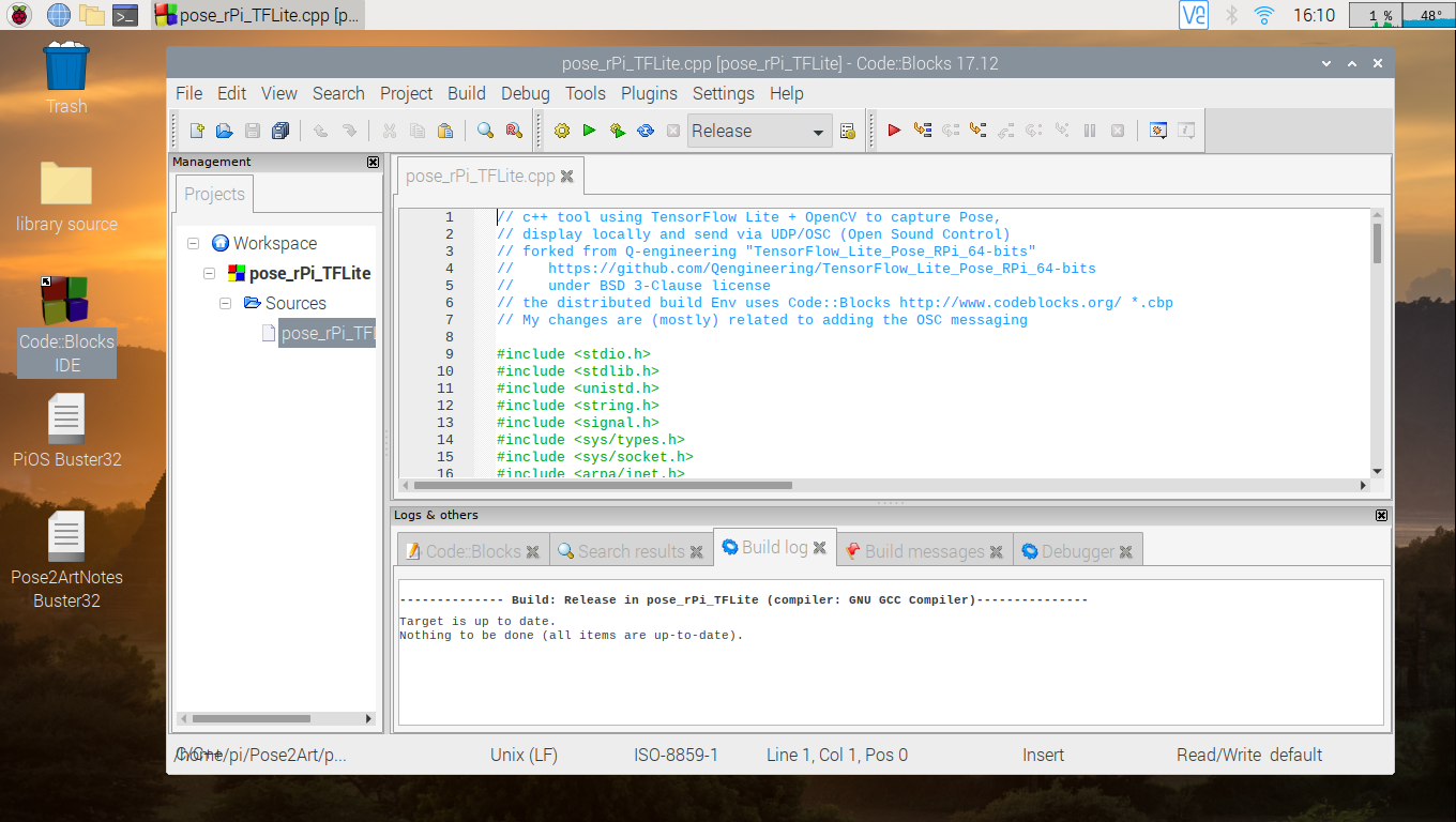
12/07/2022 at 02:35 • 0 commentsNow that we have shown the TouchDesigner Dots project working with the PC's webcam, we move on to the Raspberry Pi Smart Camera. Back in Log 1 and 2 we setup the software and networking. There should be a folder on your rPi called Pose2Art downloaded from my GitHub for this project. We are interested here in the pose_rPi_TFLite files, and will use the Code:Blocks application bundled into Q-engineering's os image to view/edit/run.
Using the File Manager window, navigate to the Pose2Art folder and double click on the file pose_rPi_TFLite.cbp. This is the Code:Blocks project and will open the tool. The Gear icon will compile the tool, and you can then run it by clicking the green > arrow in the icon row at top.
![]()
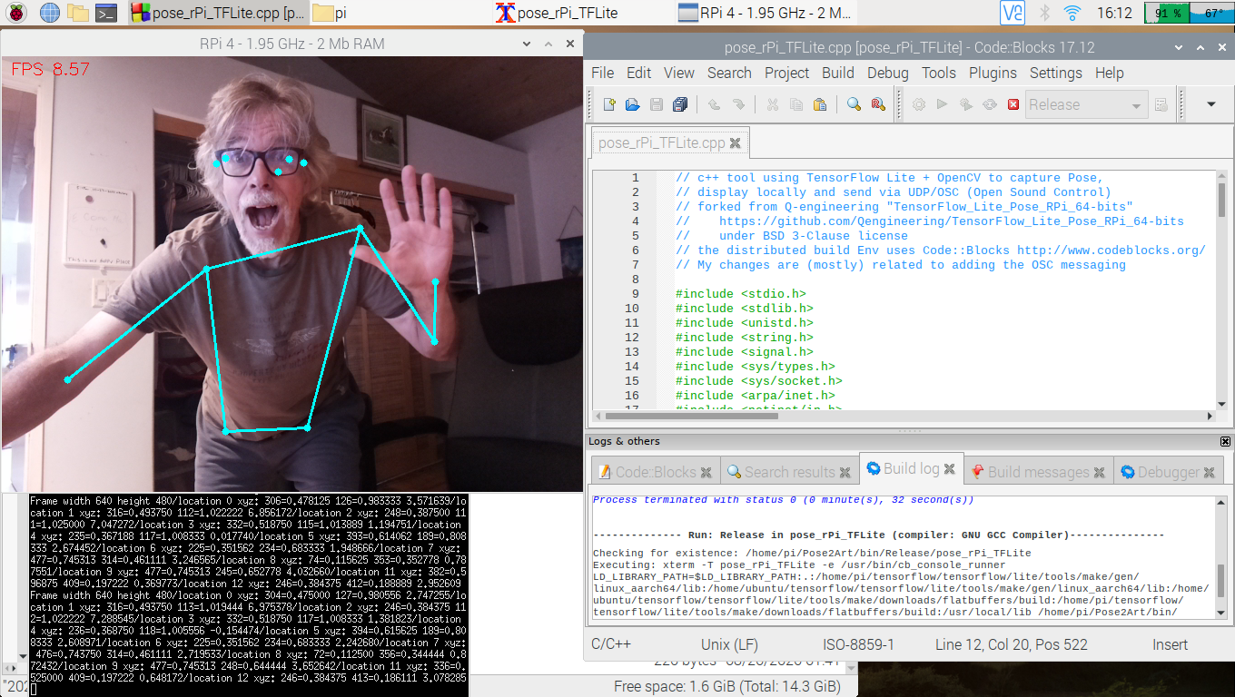
When you run the tool, two new windows will be displayed. One will be the std output (printing each landmark each frame). The other is the camera view with dots and skeleton drawn on top.
![]()
To exit the program, put the mouse in the camera view window and press ESC. Then hit ENTER to close the output window. You will be back at the Code:Blocks window.
Note there is an executable pose_rPi_TFLite in the Pose2Art/bin/Release folder. It needs to be run in the folder with the .tflite model file. If you open a terminal and navigate to the Pose2Art folder you should be able to run the tool with:
$ bin/Release/pose_rPi_TFLite
Only one new window (camera view) will be opened.
The C++ code is fairly well documented. It is a bit more complex than the Python, which is the nature of the two languages. There is more code to catch the ESC, deal directly with UDP sockets etc. Basic flow in main() is to capture a frame, invoke detect_from_video(), and display the frame with some timing overlays. The detect_from_video() grabs the image width/height then invokes the TFLite interpreter. Results come back in a couple tensors which are then used to find the locations and confidence for each landmark. It then sends the OSC messages and draws the dots/connections over the image.
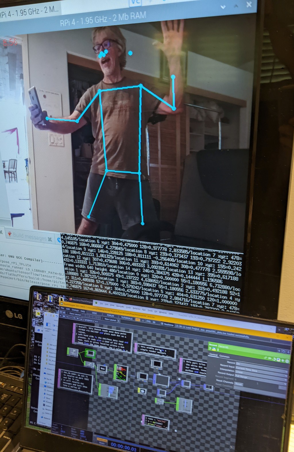
If you have the rPi4 connected to the PC, and have the Dots TouchDesigner program running, you should see the dots in the TD render1 OP.
![]()
-
Log 3: PC Code - Python and TouchDesigner
12/03/2022 at 00:52 • 0 commentsNow that we have installed the software (Log 1) and setup the networking (Log2), lets try a PC-only pose-OSC-touchdesigner project. In the Pose2Art project (downloaded from GitHub) are two files I copied/renamed from my fork of Cronin4392's TouchDesigner-OpenCV-OSC project. The python tool pose_PC_MediaPipe.py uses OpenCV, MediaPipe and Python-OSC to capture the images, extract 33 pose landmarks and send them as OSC Messages to 10.10.10.10:5005. It also shows the landmarks and skeleton lines in an OpenCV window. The TouchDesigner poseOSC_dots.toe reads the OSC messages and displays them as dots.
Aside from name changes, I added the three frame message sending to the python tool and did some other changes to Cronin4392's original. The toe file got bunch of documentation in TextDATs, and a little bit of functional change.
![]()
Python Code:The python tool (pose_PC_MediaPipe.py) captures the image, runs the pose extraction model and then sends the data via OSC. It uses MediaPipe to do the pose extraction. MediaPipe is a cross-platform, Machine Learning (ML) tool for live and streaming media, It identifies 33 landmarks including face, hands, torso arms and legs. These are sent as 69 OSC messages, with x, y and z (confidence) for each landmark. There are also three messages for image_width, image_height and numLandmarks sent each frame. The tool uses a MediaPipe function to draw the skeleton connections onto the original image, and OpenCV's circle to draw the dots before it uses OpenCV's imshow() to display the preview image. Note that the Y values need to be flipped and aspect ratio adjusted to match what TouchDesigner expects.
# modified from orig: new URL, added OSC msgs for image h,w, numchannels
# forked from https://github.com/cronin4392/TouchDesigner-OpenCV-OSC
import cv2
import mediapipe as mp
from pythonosc import udp_client

# Create our UDP client which we'll send OSC through
# Change the URL and port to whatever fits your needs
# mauiJerry: use our PC's static ip in prep for running on Raspberry Pi
UDP_URL = "10.10.10.10" #"127.0.0.1"
UDP_PORT = 5005
client = udp_client.SimpleUDPClient(UDP_URL, UDP_PORT)

# Initialize some mediapipe stuff
mpPose = mp.solutions.pose
pose = mpPose.Pose()
mpDraw = mp.solutions.drawing_utils

# Initialize our video source. It can be a file or a webcam.
cap = cv2.VideoCapture(0)
# cap = cv2.VideoCapture('dancing.mp4')

# Helper function to normalize direction and scale of y axis for TouchDesigner
def adjustY(y, w, h):
    return (1 - y) * (h / w)

num_landmarks =0
while True:
    success, img = cap.read()
    imgRGB = cv2.cvtColor(img, cv2.COLOR_BGR2RGB)
    image_height, image_width, _ = imgRGB.shape
    results = pose.process(imgRGB)

    if results.pose_landmarks:
        # first time, count number of landmarks pose model finds
        if num_landmarks < 1:
            # how do we get len/size of landmarks?
            for id, lm in enumerate(results.pose_landmarks.landmark):
                num_landmarks = num_landmarks+1
        # draw landmark connection lines (skeleton)
        mpDraw.draw_landmarks(img, results.pose_landmarks, mpPose.POSE_CONNECTIONS)

        client.send_message(f"/image-height", image_height)
        client.send_message(f"/image-width", image_width)
        client.send_message(f"/numLandmarks", num_landmarks)
        print("height, width, num marks", image_height, image_width,num_landmarks)

        for id, lm in enumerate(results.pose_landmarks.landmark):
            x = lm.x
            y = lm.y
            z = lm.z

            # Send our values over OSC
            client.send_message(f"/landmark-{id}-x", x)
            client.send_message(f"/landmark-{id}-y", adjustY(y, image_width, image_height))
            client.send_message(f"/landmark-{id}-z", z)

            # Draw circles on the pose areas. This is purely for debugging
            cx, cy = int(x * image_width), int(y * image_height)
            cv2.circle(img, (cx, cy), 5, (255,0,0), cv2.FILLED)

    cv2.imshow("Image", img)
    cv2.waitKey(1)
TouchDesigner Code
The TD project is distributed as a '.toe' file. When you open it you should see the default view is the network editor layout, showing the main level. The boxes are OPerators with lines connecting them to show data flow and dependencies. I heartily recommend watching the TouchDesigner Beginner Crash Course playlist from Interactive & Immersive on YouTube to get up to speed with TD. Their public youTube channel is full of amazingly helpful, well produced videos. When you want to go deeper into TouchDesigner (and related tools), consider their training and certification program HQ Pro.
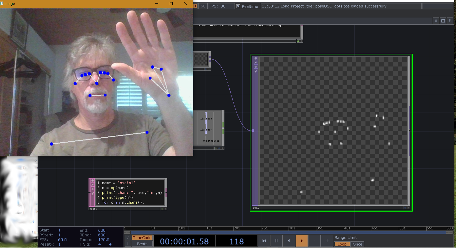
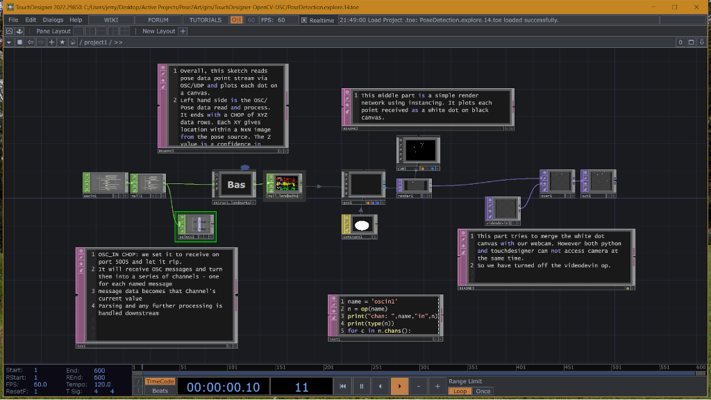
When you open 'poseOSC_dots.toe' with TD, it should look something like this:
![]()
The main data flow is in the boxes across the middle. The magenta edged boxes are Text DATs that mostly contain comments about the application. The center bottom Text DAT holds a small bit of python code that will print out all the channels (osc message type tags) that are received by the OSCIn1 CHOP. Matthew Ragan has a good video on how to use the Textport to view python print statements
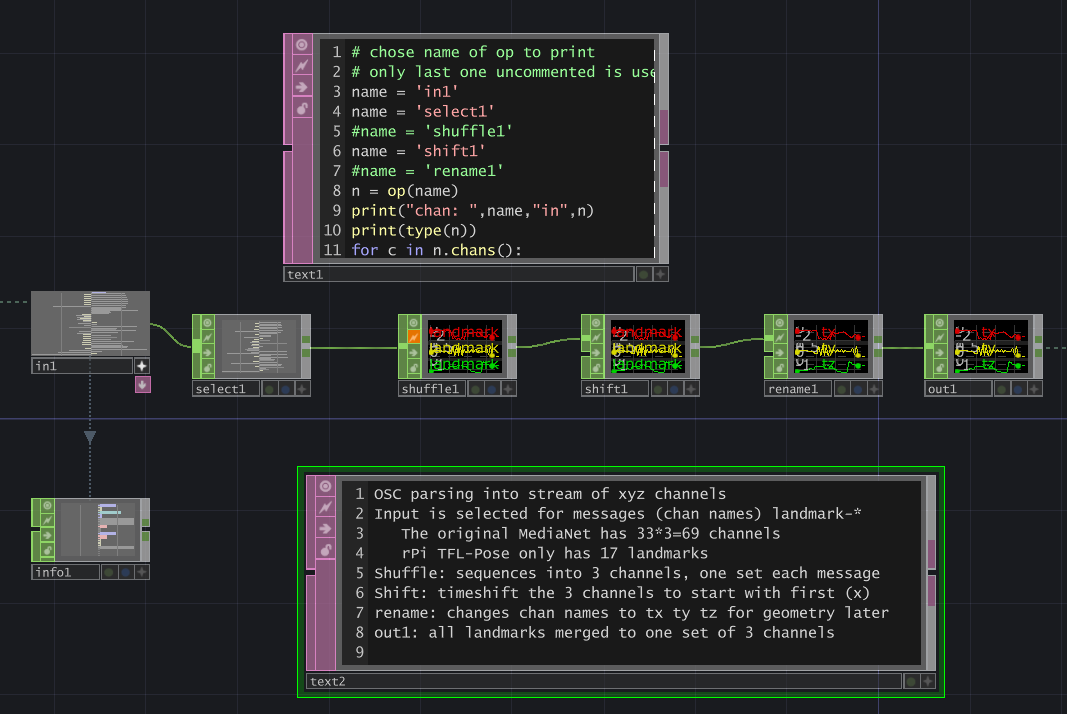
As the comment TEXTDats note, the OSCIn CHOP reads the incoming OSC messages. These flow into the 'Bas' (extract_landmarks) container, which massages the data into a stream of XYZ data. These 3 channels are used to render dots at the XY locations of landmarks on an image the size of the camera input. The right side of the network would show the webcam image overlaid by the dots, if there wasnt an access conflict. Double clicking on the Bas Container OP opens this layer to show the OSC data manipulation.
![]()
Again the Text DATs hold either python code or comments while the other OP boxes modify the data streams. Basically the container selects OSC messages with tags beginning '/landmark-' (the 69 landmark channels). These are reduced by the 'shuffle' chop into 3 channels, time shifted so each set of 3 happens at same step, and finally the channels are renamed to 'tx ty tz'. The out1 chop outputs the channels back to the parent flow. The python in text1 op can be used to inspect the channel names in each of the chops.
-
Log 2: Networking Setup: Static IP, Routing and Firewall
11/27/2022 at 06:39 • 0 commentsWireless networking eliminates the need for cables and instructions on setting up wifi networking between a rPi and PC (and router/gateway to internet) are common. During development, it is quite useful to have internet available on the rPi. I recommend finding and following some of those directions. However, an installation can run into many problems if it relies on Wifi. Worst case would be having to rely on the venue's wifi setup or some other wifi outside your control. Setting up your own wifi on site is a bit better.
Whether you go wifi or hardwired, you have to go through more steps to insure the network is secure. You need to 'harden' both the rPi and PC against intrusion, should someone gain access. It is hard to add security after a project is working and i rail against products that don't build in security from the start. But for now, we are going to do the bad thing and ignore security, except for using a wired network. I don't have a marketing dept to insist we ship the prototype, so maybe i'll get back to it in time.
Setting up the hardware side of Pose2Art's wired networking is trivial - connect a standard Cat6 ethernet cable with RJ-45 connectors between the two machines. Later, we can add a fast switch and connect multiple smart cameras, but the hardware side doesn't get much more complex (until you add a router/gateway). I did find that it is important to have the cable connected in order for the software setup to work.
The software side IS a fair bit more complex, especially on the Win10 side. I spent a lot of time and explored several failed paths. Unfortunately my notes are lacking in some areas. The setup described below works for me, but I cant test it from a clean start. If the steps dont work for you, please dig in to the links and let me know what helps! I recommend the Wireshark tool for helping diagnose networking issues.
There are three important parts of the networking software setup: static IP addresses, static routing, and firewalls. Setting up Secure SHell (SSH) and Virtual Desktop access from the PC to the rPi is sometimes desireable, if you are willing to tolerate the security risks.
The folks at Interactive Immersive HQ have a nice (not too technical) introduction to networking for TouchDesigner (TD) in 3 parts. I heartily recommend their site for both free and paid pages. While $140/mo (roughly) is expensive for dabbling, their videos and blogs are well worth the price for professionals. If you are just getting started with TD, watch their Crash Course videos.
Static IP Address
Modern networking requires each device have a unique address. A media access control address (MAC address) is a unique identifier assigned to a network interface controller (NIC) for use as a network address in communications within a network segment. A device with multiple NICs will have different MAC addresses for each. Devices connected using Internet Protocol (most common, bog help you with others) and will need an IP Address. The networking software and configuration of the device maps the MAC to IP address. The most common method is to use Dynamic Host Configuration Protocol (DHCP) and most of those Wifi Setup articles will talk about using DHCP. However the Pose2Art project does NOT include the DHCP server (usually the wifi router) that assigns the mapping. We use the "Static IP Address" technique where the device NIC has its IP Address defined in the configuration tables. This requires a bit of setup before you can use the network.
For our prototype we will use the IP Address subnet 10.10.10.XX, where the first 3 numbers define our subnet address space and the XX will be set for individual machines. The PC will get the IP Address 10.10.10.10 and the first camera system will be 10.10.10.11. Future cameras would increment from 11 for their addresses. Subsections here show how to set these up on rPi and Windows 10. If you are using a Mac or other OS, you will need to find instructions elsewhere.
Static IP Setup on Windows
There are lots of tutorials online about setting up Static IP addresses on Windows 10. I used this one from PureInfoTech.com to configure the PC's wired ethernet NIC.
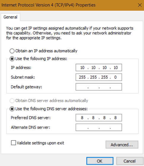
I used the Control Panel >> Change Adapter Settings to set the IPV4 properties address to 10.10.10.10, mask to 255.255.255.0 and left the Default Gateway blank and set the Preferred DNS to 8.8.8.8 (although it wont be used). Note this connection will not be active until the rPi is connected with the PC.
![]()
Static IP Setup on rPi
There are at least 3 different subsystems for linux ip addresses. The default on rPi Buster (and Bullseye?) is DHCPCD. The others we will ignore as they are either outdated or too new. Dhcpcd is primarily configured by the file /etc/dhcpcd.conf.
Open /etc/dhcpcd.conf for editing in nano.
nano /etc/dhcpcd.conf
If you havent mucked with it before, this file will be setup for your wifi access with little or commented lines for the eth0 interface. Using Nano (or your preferred editor), add these lines at the bottom:
interface eth0
static ip_address=10.10.10.11/24
static routners=
static domain_name_servers=8.8.8.8
note we are not defining router and giving a generic domain name server at this time
Static Routing
Next we need to configure the 'routing' of IP messages. This defines how the networking software sends (routes) messages. The normal (dynamic) wifi setup using DHCP lets the router device do all the work, but you do not have control over which device gets which IP address. We need a static addresses so we can send messages from rPi to PC and do SSH/VirtualDesktop from PC into rPi.
Static Routing on Windows 10
add static route to 10.10.10.x via the ethernet NIC. Some systems may have multiple NIC so be sure you configure the one you are using for the rPi. These command may require the ethernet cable is connected to the rPi4.
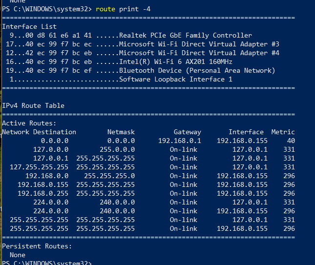
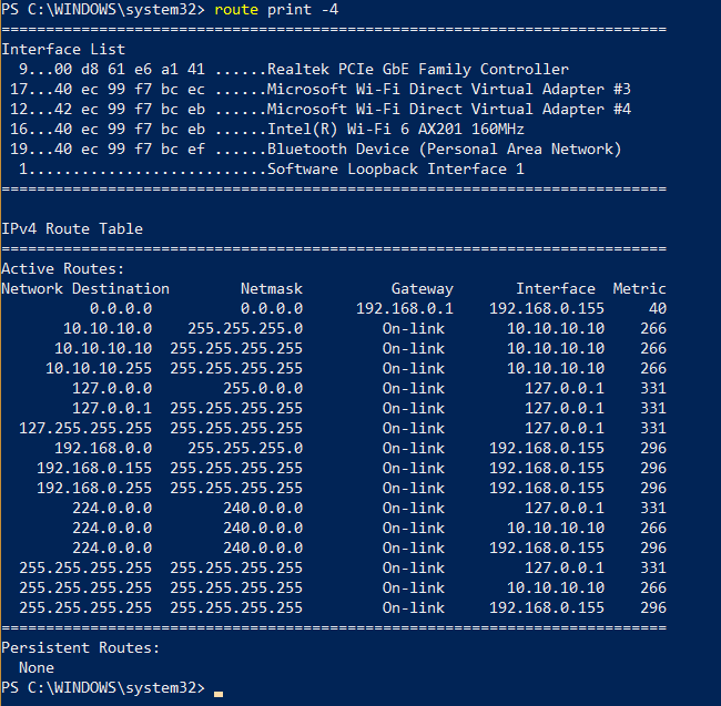
Following the instructions in this link, we run the Windows PowerShell in Admin mode and enter a few commands. First we check the default routing for IPv4 with the command "route print -4"
![]()
From this we see that my wired NIC has the ID of 9. Remember that number. The active routes are those provided by my wifi router. To setup the static routes we need to Add the information. Note the use of '-p' flag to make the changes Persistent. Otherwise they would go away on next system boot.
route add -p 10.10.10.10 mask 255.255.255.255
route add -p 10.10.10.255 mask 255.255.255.255
re running the route print command, with Ethernet cable connected to running rPi4, I get the following routing table:
![]()
You can see routes are added. I am not sure about the 10.10.10.0 route. I may have added that as well during my explorations.
Static Routing on rPi4 Buster
To configure static routing on the rPi4 we need to create the file /etc/dhcpcd/dhcp-hooks/40-route. A simple way to do this is using Nano editor to create the new file.
sudo nano /lib/dhcpcd/dhcpcd-hooks/40-route
Then enter the following text, save the file and exit.
ip route add 10.10.10.0/24 via 10.10.10.11
then reboot the rPi .
Windows Defender Firewall Configuration
Firewalls are software that protects your system from malicious or improper remote access. Unfortunately they are necessary for any machine these days. The router that connects you to your internet service provider likely has one available, and should be configured to provide at least some protection from the outside.
Windows 10 includes its own Firewall called Windows Defender Firewall (WDF). I originally had added a 3rd party firewall and other utilities (anti-virus etc) but these slowed my system and were difficult to configure. Friends in the IT industry recommended getting rid of the 3rd party stuff and sticking with WDF., so I ditched the 3rd party one. Configuring WDF still turned out to be a long slog. In the end I wound up disabling WDF for the wired NIC. It works, but I am not happy about the security risk. Have to remember to turn it back on when I use the hardwired NIC for other purposes.
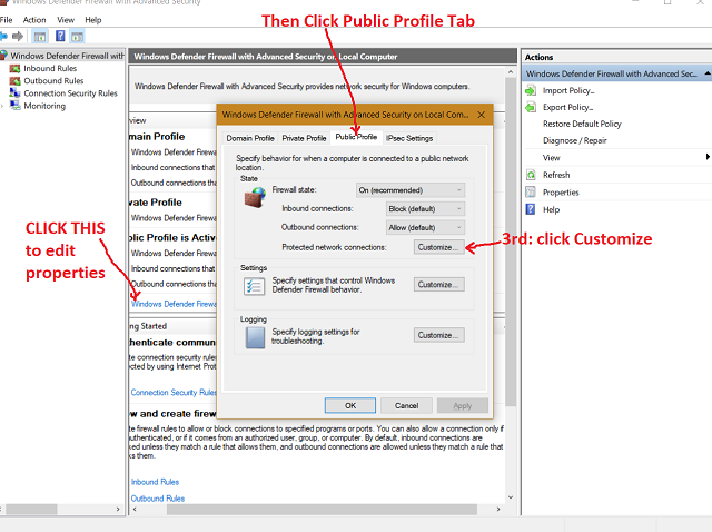
- open WDF
- Click on "Windows Defender Firewall Properties" (blue text in right pane)
- Select Public Profile tab
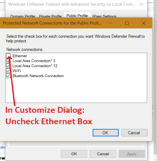
- Click Customize button next to Protected network connections,
- Uncheck the "Ethernet" button
- Click OK to dismiss the customize dialog
- Click OK to dismiss the Properties dialog
it should be working now. Test using the udpSend.py on rPi4 and udpReceive.py on PC
![]()
![]()
Alternative attempt notes:
The default configuration of WDF does not allow UDP, Ping and other connections over our link. This article explains how to let Ping commands through WDF. Basically you enable a rule for File and Printer Sharing on IV4.
For a rule to allow UDP in on ethernet NIC (advanced Settings), I tried the method described in this video. Alas it did not seem to help.
If you find a solution that works, please tell me.
Testing Network Connection
I used two tests to prove the internet connection: Ping and Python UDP Send/Receive
Ping
Ping is a common networking utility used to test the reachability of a host computer, and measure the round trip time for a message. Ping operates by means of Internet Control Message Protocol (ICMP) packets. Pinging involves sending an ICMP echo request to the target host and waiting for an ICMP echo reply.
On the Windows 10 machine, open a Command Prompt (or PowerShell) and enter
ping 10.10.10.11
It should respond almost immediately with results. If it doesnt, check the routing using PowerShell "route print -4" as above. If that shows the route is open, hmm, idk.
On the rPi4, open a terminal window and enter the command:
ping 10.10.10.10
If it does not return values right away, there is a connectivity issue. If the Win10 machine was able to Ping, then it is likely a Firewall issue. Check your settings.
Python UDP Send/ReceiveI created a simple pair of python programs: udpSend.py and udpReceive.py. You can find these in my pyUdpTest github repository. They use the same IP address and port I have set up for my Pose software (see a later project log). I used Python here because it is very simple and portable. The code runs on both Linux and Windows machines, unlike the C++ code in the Pose application.
SSH/VirtualDesktop
During development, our prototype rPi has its own keyboard, mouse and monitor, but an installation will be 'headless' (none of those). It is useful to have access to the pi remotely from the PC, and this is easily accomplished using either Secure Shell (SSH) and/or Virtual Desktop. See the Raspberry Pi Documentation on Remote Access for instructions on enabling these. We already know the IP address (10.10.10.11) so you can skip over that section.
-
Log 1: Linux and Windows Software Setup
11/27/2022 at 06:33 • 0 commentsThe first step after acquiring your hardware will be installing the basic software. I dont have a Mac to test that side, so you Apple folks are on your own there.
Windows Rendering PC setup
Windows system basically needs just TouchDesigner installed. If you want to try the PC only pose-osc application (pose_PC_MediaPipe.py), you will need Python3 and some additional API. This application uses the PC's webcam to capture the pose data and send it via OSC.
$ pip3 install opencv-python mediapipe python-osc
You may want to get a python development environment like PyCharm too.
If you are going to run the python PC test tool pose_PC_MediaPipe.py, you will need to install the required dependencies. I strongly recommend using Python3. Note that TouchDesigner has its own Python installation separate from any system of venv you have on your PC.
Lastly, (fork and) download a copy of my GitHub code.
Linux Raspberry Pi Setup
Setting up Linux and all the software on the Raspberry Pi 4 can be simple or a long confusing process. Don't despair! There are simple steps below.
The basic operating system on rPi is pretty easy - download the Raspberry Pi Imager on your development machine and use it to install the OS on an SD card. There are lots of tutorials on the web that will walk you through such setup using your Wifi Network to get updates, etc. This tutorial from Qengineering can walk you through setup of the rPi OS (but read below first!!). Qengineering has a number of quite informative blogs and other repositories. I heartily recommend checking them out.
After initial setup, you need to get all the various libraries (tensorFlow, openCV, liboscpp, etc) for your projects. There are many versions of these and they have dependencies on various other libraries. Getting the right versions of the right libraries can be a very frustrating and time consuming process. Often you have to rebuild them from the source code - which may require other tools, and the right versions of those. Welcome to Dependency Hell.
HOWEVER - there is an easy way! Qengineering has a built a Raspberry Pi 4 64-OS image with deep learning examples. Download the image from that GitHub repository and use the Imager tool (link in previous paragraph) to copy it to your SD card. Couple caveats: it is a 16GB image and if you use a larger SD card it will be wasted, also while this is a 64bit OS, it is Linux v10 Buster not the newer v11 Bullseye. That is actually ok for us as v11 changed the whole Camera Driver subsystem (see link in first paragraph above for Qengineering info about that). Most of the demos out there are built for v10. This will change over time. For now the v10 Buster image is fine for our prototype. The image has a number of other tools and examples besides TensorFlow's Pose Estimation, so you can explore those. Check out Qengineering's github and blog posts for information on these.
During the initial rPi4 setup, it will be helpful to setup wifi access to your development network. You will also want to configure the rPi4 to access the Camera, SSH and Virtual Desktop. Most rPi setup tutorials will walk you through how to do these.
There are some rPi4 tune-up options that help with heat dissipation and some other aspects. This video runs thru them. My machine was already up to date on them.
The only other dependency software we need on the linux side will be liboscpp - a c++ library for OSC. The github repository for liboscpp has good instructions on how to install it. I'd copy them here but if they update the library my instructions will be out of date. Read down in those instructions for the RaspberryPi specific instructions.
Lastly, (fork and) download a copy of my GitHub code to your Pi.
Next Step: Networking Setup
Next you will need to setup the Networking between the rPi4 and your rendering system, which is different than the usual wifi setup. I'll cover that in the next project log.
Pose2Art: SmartCam to TouchDesigner, Unity via OSC
Create an AI Camera run on small 'edge' device that extract Pose and sends tracked points via OSC to TouchDesigner and Unity for ART!