Monday, 13:38, 26/12/2022
I didn't had an idea for a Project Log 18 yet, but since I added so many off-topics on Project Log 17, my Hackaday website started to lag and I was afraid of resulting in the same problem/bug that happened in the Project Log 16.
Now that I think about it...
I feel like the Project Logs are taking more and more time to be made and its subjects are getting harder and harder to calculate.
The fact that I procrastinate 80% of the time doesn't help...
But I do feel that I deeply underestimated the difficulty to actually complete this project log in specific.
And guess what? I was right.
I barely scratched the surface of the 2º topic, and the Project Log is already lagging and bugging.
So, unfortunately, I will be forced to postpone the 3º topic to other project log, because I feel like I will beat my head a lot trying to figure out the structure.
Okay, first, let's list what I need to talk about in this project log:
- Materials:
Let's talk about possible materials that I could use.
Such as Aluminium, Steel, Carbon Fiber, Wood etc. - Fuselage and structure:
Then let's find the best shapes these materials could withstand force and how to calculate these things. - 3D modelling.
Let's design a basic 3D sketch model based on these new shapes.
Off-Topic:
Also, I just found out about wax motors
and it gave me an idea. Basically, Wax Motors are linear actuators that are used as solenoid valves in some applications. It uses a wax-copper/heating element mix, which helps melting it.
Obviously, I won't use paraffin wax actuated McKibben muscles, simply because they are slower than a snail.
However, as you people may remember from Project Log 1, "polyethylene/nylon artificial muscles are not viable for control and actuation, because they are slow and need a lot of surface area".
HOWEVER, if I mix copper powder, heating element powder (like carbon fiber powder) just like the wax motor, I will (maybe, perhaps, I think, probably) exponentially increase the contact area between the nylon and MAYBE allow it to contract like a muscle without the need for kilometers and kilometers of nylon fiber.
I will just buy a 5 dollar nylon rod from aliexpress or something like that and then test it out (with aluminium foil and graphite powdered in a blender), I will need to make a lot of holes so the nylon can easily contract and cool down with circulating oil.
(yes, this was an impulsive purchase that I will regret for the next 99838923 years, even though it is just a couple of bucks)
Or, maybe, I think I will try to pass air flow through the molten nylon in order to make it porous, or just mix it with alcohol and wait the thing to scape (and not burn my house down).
One could make a personalized 3D printing filament in order to do that, but I don't have the money, nor the will to get all that trouble.

Art taken from Vitaly Bulgarov Artstation account.
And yes, he did make the concept arts for the Ghost in The Shell live action movie. The script is bad, not the art, and for a good reason. ;)
1. Materials:
Besides, I could just use carbon fiber...
Wait, no. Actually, I'm avoiding using carbon fiber and/or fiberglass.
Simply because these two are messy and dangerous to work along without any kind of protection, not to mention that these can't be recylced...
I could use wood with resin tho...
The original article about the subject: "BYU Engineering Student Develops Bamboo Fiber Composite Material".
There are also Wood-plastic composites:

I could use polyethylene (a strong type of plastic, used even in bulletproof vests and milk jugs) as a matrix/binder and wood fiber composites.

A few types of composites.
2. Fuselage and Structure:
I don't think I talked about this clearly enough on Project Log 16, but basically, the idea of using aerospace engineering techniques was to make the fuselage/endoskeleton of the mech as light as possible and able to withstand the most loads as possible. Which is a way of circumvent the safety issue of smashing everything in your way by accident.
You can use CNC laser cutting wood for that, and still getting incredible amounts of strength while being lightweight.
I just need to figure out how to calculate all this crap... >.>
Well, I tried to ask around, and I got no answers, and the answer I received were "why not just make it like *machine that already exists*? It is easier than reinvent the wheel".
Anyway, someone actually suggested me a motherfricking Forklift design, for my "lever".
Well, I don't have a forklift certificate, maybe that's why I'm maindenless, lol.
Also, yes, I'm still asking around.
Asking things like "I need a mechanical lever that can lift 5 tons, but I need to save wait, so I'm trying to find a way to calculate and design a monocoque/semi-monocoque design, could you help me out?".
Maybe not the best written text/question to ask around, but hey, I'm trying dude...

And guess what? Everyone tells me that I should just make a tube, that I should just pay an engineer and so on.
Bruh, I'm broke and I'm trying to save some lives here, saving lives by not smashing them under this stupid mech.
Well, I guess that I will run into the same problem as the chatbot: you can only get a good, detailed answer if you ask a good, detailed question.
The output is as good as your input.
So, let's try to ask a good question here:
"Would this mechanical lever with semi-monocoque structure withstand 5 tons of weight?
In resume, I'm interested on making a semi-monocoque structure that need to be lightweight and strong enough to withstand 5 tons of weight in a small point of the structure (around 5-10 cm of area).
Until now, I thought on the following:
The entire structure would be a cylinder with 30 cm of length, and 15 cm of diameter. The primary material would be aluminium.
The inner disks would be 1mm thick aluminium plates separated by nuts with 2cm of height used as spacers.
The aluminium shafts/rods with 8mm in diameter would pass through these nuts, totalling 10 shafts in a ring. You know, just like a semi-monocoque structure.
Finally, there would be a "i" linear plate with 30cm of length, 15 cm of width and 1mm of thickness passing through the structure, which would be more like a "spine".
Would such structure be able to withstand 5 tons?
This is meant to be a mechanical lever with an axis of rotation, but for simplicity sake, just imagine this as an static cylinder that will have 1 point where 5 tons of weight will be applied.".
Well... Bad news.
I couldn't find anyone that can actually reply me, simply put, it is too damn complex.
The reasons I wanted a semi-monocoque design:
- It is lightweight, so in case of colision iwth humans, it would be innofensive.
- Since it is lightweight, the muscles would nees to apply less pressure.
- Depending on how one designs the structure, it would be easier to build.
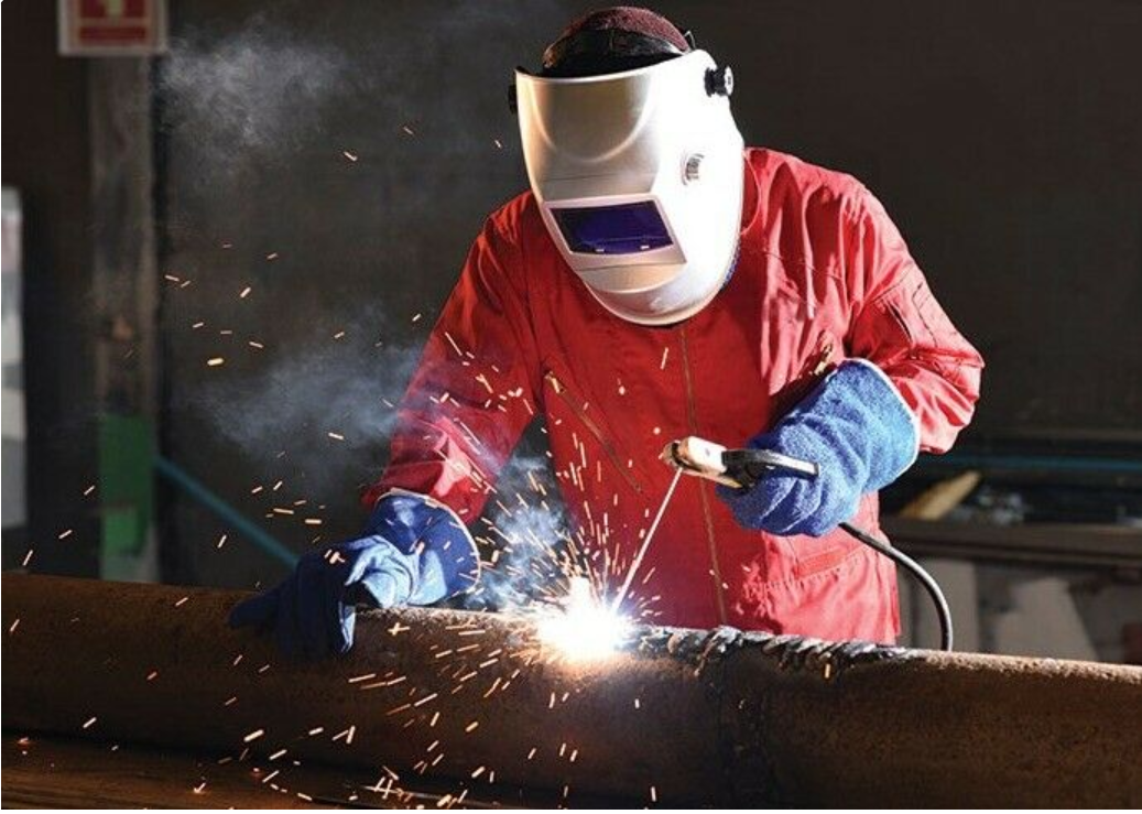
I don't know about you, but it certainly is easier, cheaper and safer to put a lot of plates together with nuts and bolts instead of heavy welding everything with a torch or a high voltage welding machine.
Also... This made me remember something about our bones:
The video shows the inner structure of the bones.
It is basically like what we do in 3D printing fills:
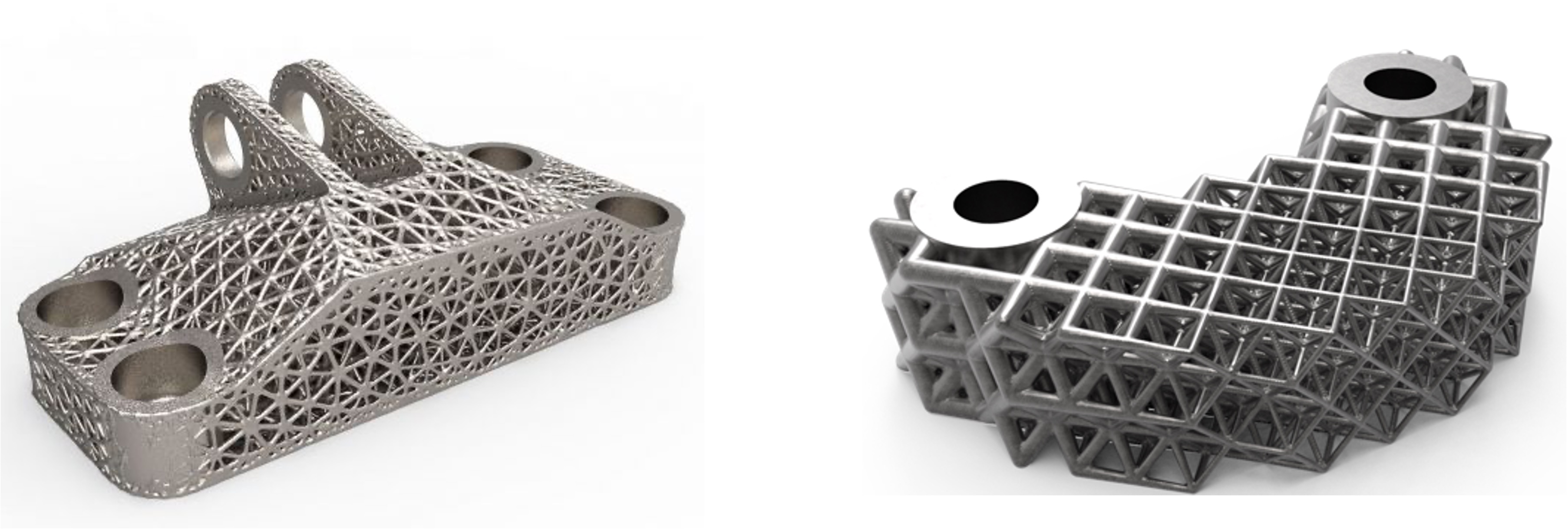
And since we are in the topic of 3D printing here, let me confess something:
I'm a little hater of 3D printing... For some engineering applications.
It is just so fricking overhyped when they can't even compare to cast pieces (in certain applications)...
For those who don't know what casting is:

And both of these methods are (in a really general way) not as good as subtraction manufaction (in some applications).
But subtractive (aka "machining"), can be more expensive.

Each method has its advantages and its disadvantages and each application may require different types of manufacturing.
One cannot simply say one method is better than another, you need to play with its advantages and limitations in order to squeeze the best each method can produce.
A great casted part may not be viable through the machining method, a great machined part may not be viable through the casting method, and a great 3D printed part may not be possible in both these methods.
You cannot produce certain things with machining, you can't make certain things with casting and you can't just 3D print the fricking world.
And that is why I'm kinda of a hater of 3D printing, except I don't make talking about it my entire personality, like normal haters, lol.
Also, I bought a plastic FDM Ender 3 3d printer, and my god, I f*cking hate that thing. It is as frustrating to use as conventional ink printers.
By the way, there are other methods of manufacturing.
Maaaany more methods.
And that is one of the reasons why I got so interested on continuum robots, you could (hyphotecically) make something as complex as a laser 3D printer; using the cirurgically precise continuum robots to cave a path through the structure.
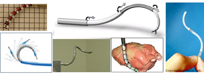
But it would also have its limitations, and it wouldn't be able to make things super precise without trade-offs.
For example, while machining, depending on the method, a more rigid structure is preferable, because it is easier to calculate and thus, make it more precise.
And precision is expensive as heck.
But how to make it at home? And in a budget?
You would need fiber lasers, maybe a water jet cutter, or a plasma cutter.
I don't have any of those.
I thought on using the technique this video bellow shows though, but at a lower pressure; because his power washer breaks down and he buys a stronger one.
I would "just" need to figure out the rate the material is subtracted from the part, and then figure out how to make a continuum robot hoose that doesn't fly all around like those firefighter hoses.

Anyway, back to the topic:
I just remembered about the backhoe loader structure, for some reason, its arm is in a wide "v" shape:
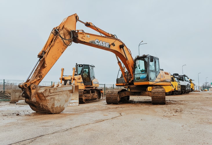
I don't know why they are like this, but I think it is worth looking into it and maybe adopt that to the structural design.
Oh yeah, I also completly forgot about this cellular lattice strucutre made by NASA and MIT inteded for air planes:

Image above took from here: "These NASA and MIT researchers created a shape-shifting airplane wing that could change air travel".

Original scientific article here: "Reversibly Assembled Cellular Composite Materials".
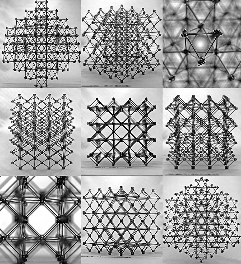
Image taken from here: "How to make big things out of small pieces".
These kinds of lattice structures makes a knot on my brain... I have no idea how to calculate the ideal size for my application.
And yet, it is quite an interesting structure. It is absurdly light, it can be easily mass produced, even at low budget levels and are inifinitely modular and constumizeable.
However, I don't know how to model them, how to calculate them, and all the informations I can find about them are like "here is the prototype, I can do this, this and this" and never "here how to do it at your backyard".
And for obvious reasons, it is a study article, not a video-tutorial. And that is the biggest limitation of this project and mine: knowledge.
And knowledge needs time.
Of course there is always the good old aluminium extrusions, but I don't know if these could withstand 5 to 6 tons...

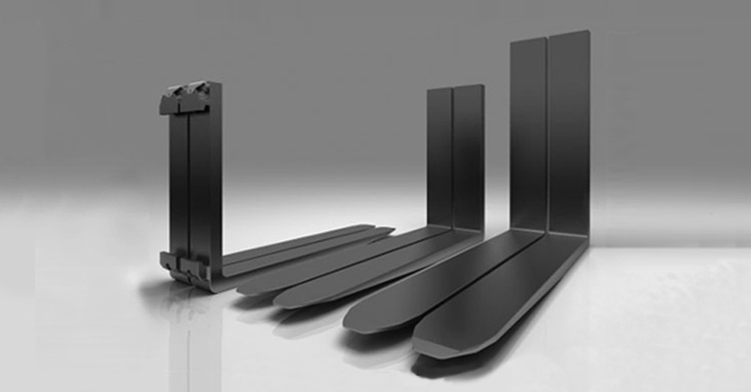
Also, I just found out these slotted steel bars, also known as "industrial shelfs" or "Drive-in pallet racking":

This looks interesting, but I do remember messing with those when I as smaller and... These are not nice to manipulate with your barehands, specially if these are rusted.
I also don't think I would feel safe with a super thin metal plate almost like a sword hitting me at any speed...

There is also metal pipe/tube connectors, but I don't know which one can withstand 5 tons or more.

Now that I stopped to think about it, aren't my requirements for the artificial endoskeleton just too proposterous?!
Like, think about it: a car, a fricking car weights around 1 ton (or 3000 pounds).
And I want five of them in the middle of a 30 cm long tube??!!!!!/1?!?!//??
Well... All of this crap would be sooooo easy if I simply wanted to make a normal exoskeleton or robot, but nooooo...
And on top of that, I would need to make the actual thing to withstand even more weight for redundancy sake...
7 cars on top of each other.
AAAAAAAAAAAAAAAAAAAAAAAAAAAAAAAAAAAAAAAAAAAAAAAAAAAAAAAAAAAAAAAAAAAAAAAAAAAAAAAAAAAAAAAAAAAAAAAAAAAAAAAAAAAAAAAAAAAAAAAAAAAAAAAAAAAAAAAAAAAAAAAAAAAAAAAAAAAAAAAAAAAAAAAAAAAAAAAAAAAAAAAAAAAAAAAAAAAAAAAAAAAAAAAAAAAAAAAAAAAAAAAAAAAAAAAAAAAAAAAAAAAAAAAAAA
I got an answer.
Basically, I would need either a 9cm diameter solid metal rod, or a 11cm diameter tube, where the inner hole would have 2cm of diameter.
And that would be for temporary loads. TEMPORARY LOADS, if I where to make an static load tube, I would something even more monstrous.
Accordingly to this steel rod weight calculator that almost got me a heart attack, this thing would weight 0,0153 tons, or 13,8 kg (30,5 pounds).
Which isn't as heavy as I though it would be...
But taking into consideration that we have... How many bones again?

...
...This many.
Of course, taking out the smaller mones, axis, and not considering that some bones are bigger than 30cm and smaller than 30cm and so on.
We would have 128 bones.
128 x 13.8 = 1766.4 kg (3894,2 pounds)
1766.4
1766.4
1766.4
1766.4
I think I've made a mistake.
We have no option, let's see how carbon fiber and glassfiber goes.
Edit¹:
Well, nobody answered me, and the ones that answered me are kinda useful, but really demeaning.
The problem CANNOT be answered - to any degree of real answers between 0.1 (units long, units being undefined at present) to a parsec.
YOU have not told us (who are trying to answer your question by asking for data so we can make a free estimate worth reading) the length between the two/three/four/five/six (or more supports)
YOU have not told us what the method of failure could be: Excess sagging? Minimal sagging? Too expensive to purchase? Shear force? Imprint force of the 5 tons into the surface? Fracture? Plastic yield after long periods of time? 2% bending failure? 10% bending failure? Failure after 3,000,000 cycles? Failure at -40 deg C? Failure above 200 deg C? Failure by tension - if the 5 tons were pulled from below? What kind of suspension(s) at each point of suspension? Common or linked suspension or independent? What minimum safety factor for the product? What maximum safety factor?
Yes, all of this information is useful, which I could take into consideration in future calculations.
But bruh, I asked this thing on quora, with a smaller word count per question than twitter.
It is a generic-question-asking website, and I asked a generic question.
Anyway, if a 9cm in diameter solid steel rod can withstand 5 tons, I'm damn sure a 9cm diameter solid carbon rod would out-perform it.
I just need to figure out the fiber glass rod.
I also found this steel beam calculator and this other steel beam calculator, which says that...
These say a lot of stuff that I don't understand...
Like, they say a beam called "HSS2.375X0.250" would definitely pass the load test.
But how a f*cking "HSS2.375X0.250" round beam looks like?

I tried to put the name on google, but it didn't show anything.
The second says that a steel grade "S275 (EN10025-2)" would do the job?

So, this would have a 10cm of diameter and 1cm of thickness and would withstand 5 tons?
Just now I noticed that I've inputed 20 kn (20000 newtons), but we are playing with 50 kilo newtons, which... Gave totally different results?
Now it is saying that a round steel beam with 193 mm of diameter and 11mm of thickness (19cm by 1cm) would easily withstand that...
Which is odd...?
Well, maybe it is calculating the load of 50,000 newtons distributed equally over its entire surface...
Which...
Which I didn't think before now...
This entire headache of a matter is because I'm applying 5 tons to a single point, no?
Wouldn't be more efficient to simply distribute the weight by placing steel throughout all the arm structure?
Like a mix of a beam lifter and a bridge cable...

And AAAAALLL this headache... Just to calculate the forearms...
How the heck I will calculate the rest, dude? y-y
Bruh... We really need an engineer to help us...
Like I said in the beginning, the project log isn't even finished, but it is already bugging the website.
Unfortunately, I will have to postpone the 3º topic for other Project log, because it is really a big challange to just calculate stuff...
Discussions
Become a Hackaday.io Member
Create an account to leave a comment. Already have an account? Log In.
I do agree that 3D printing is overhyped in many ways, but it is still very useful. Not so much for end-use robot parts, but for jigs, molds for carbon/glass fiber parts, reusable patterns for sand casting, or disposable patterns for lost-PLA casting. You do still need traditional machine tools to refine any features on cast parts that need to be smooth and precise, but it's a lot less wear and tear on your machine and cutters, and you can use cheap scrap aluminum.
Are you sure? yes | no