I created this freezer to support an experiment. It is designed to freeze a chunk of material, thaw it out, and repeat indefinitely. I have run it continuously for a month now.
I initially started thinking that a single layer of peltier elements cooled in a water bath would be enough, as the rated performance supports a delta-T of 65C. That is not the case. Each peltier can practically maintain a 17C delta-T, so if I wanted to go below freezing I needed to put a second layer of peltiers on. Each peltier also wastes about 4W of heat for each watt cooled, so for each second layer peltier four elements are needed in the first layer. Otherwise the whole thing turns into a hot mess.
I also found that a water bath is not enough, and the set-up requires forced cooling to be effective. Either a lot of fans, or flowing water. I use chiller elements to accomplish this.
The freezer works best with insulation. It will freeze ~50g of water in about two hours when insulated, using 16C cooling water.
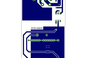
The electrical design is relatively simple: the Pi Pico turns on a transistor with its digital logic current, which turns on the relay with its USB current, which flows power from the PC power supply. I used heavy gauge wire, very short runs and lots of solder to avoid overloading the perfboard traces.
The relays are latching relays. I used 3V ones because I thought I could run them directly off the Pico and they were cheap. Nope. Luckily, latching relays waste less power, and let the transistors live longer. I also didn't realize what latching meant when I ordered them. If you wanted to have really pinpoint temperature control you should consider replacing the relays with MOSFETs. At least use 5V ones.
There are two sets of transistors as the relays also suck down a lot of current when activated, and there needs to be a set to latch and unlatch each relay. They could probably handle three relays each though.
The whole shebang is powered by a PC power supply. I used two peltiers per 12V 4-pin connector to stay within the rated current. Each peltier sucks down 4-5A and that's the only thing about them that's to spec.
You might notice there are 5 peltiers but only 4 on the diagram. That's because I switched to the double-layer design later and ran the final peltier directly from the power supply. You can probably gang the final peltier off one of the existing relays or add a fifth relay. I would recommend using a terminal block instead of soldering peltier leads to the board.
Final bill of materials:
- 5x peltier coolers TEC1-12706
- 4x 2SC2274 transistors (ECB, the datasheet I found had a backwards pinout so be careful)
- 2x DS18B20 digital thermometers
- 2x 20x4cm water chiller blocks
- 1x Pi Pico with Micropython
- 1x SPST switch
- 1x 4.7k ohm resistor
- 1x 4.7 ohm resistor (drops voltage into a safe range for the 3v relays)
- 4x DSP1a-L2-DC3V latching relays
- 1x perfboard
- 1m 22Ga solid wire
- 0.3m 20Ga solid wire
- 3x 4-pin AMP power connectors (male)
- Solder and flux
- Thermal paste
 Saabman
 Nicholas Amrich
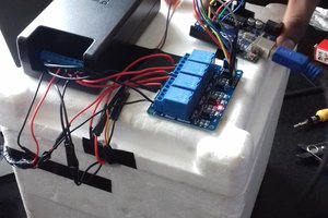
 Shreyasvi Natraj
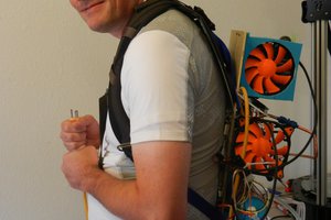
 extremerockets