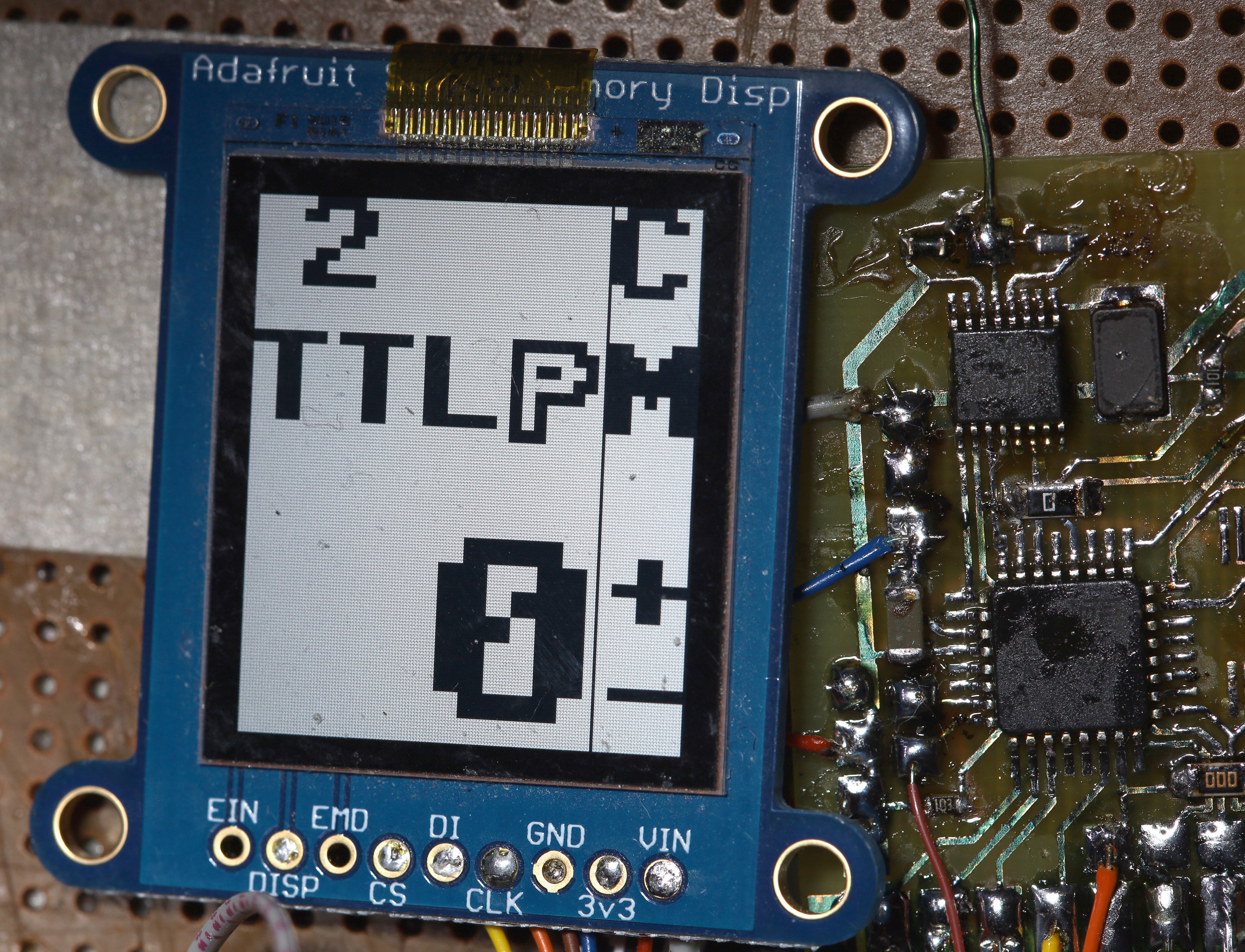
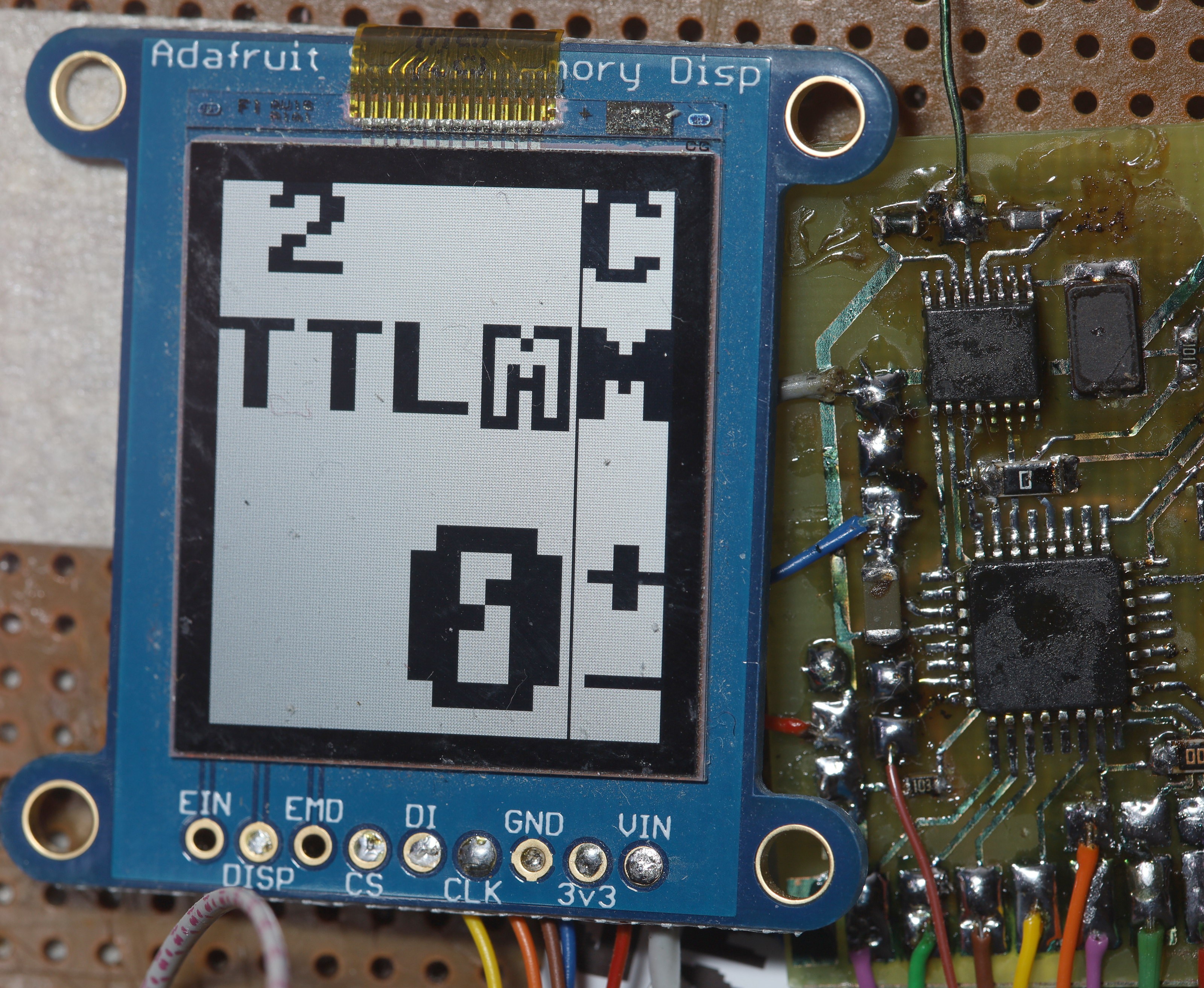
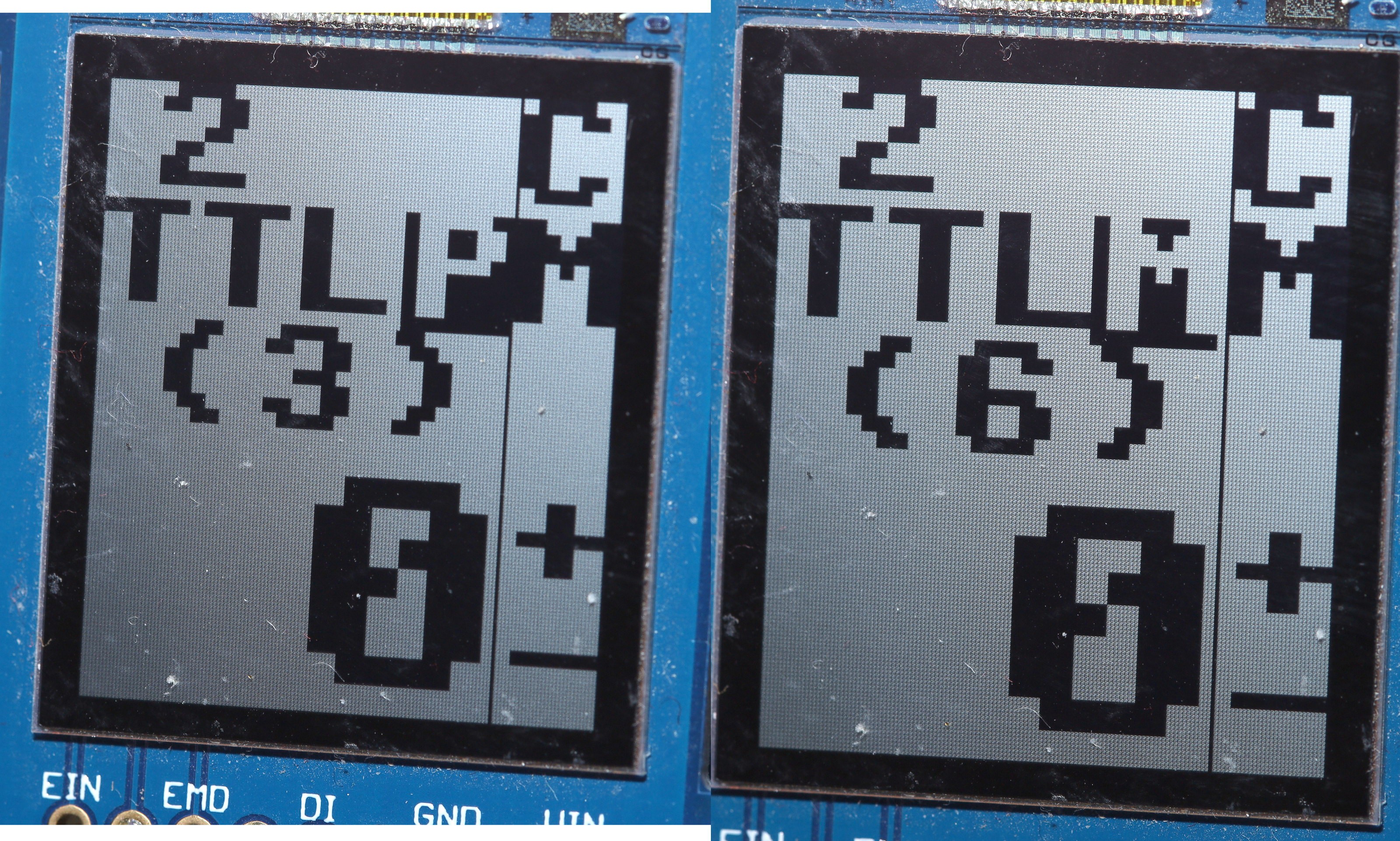
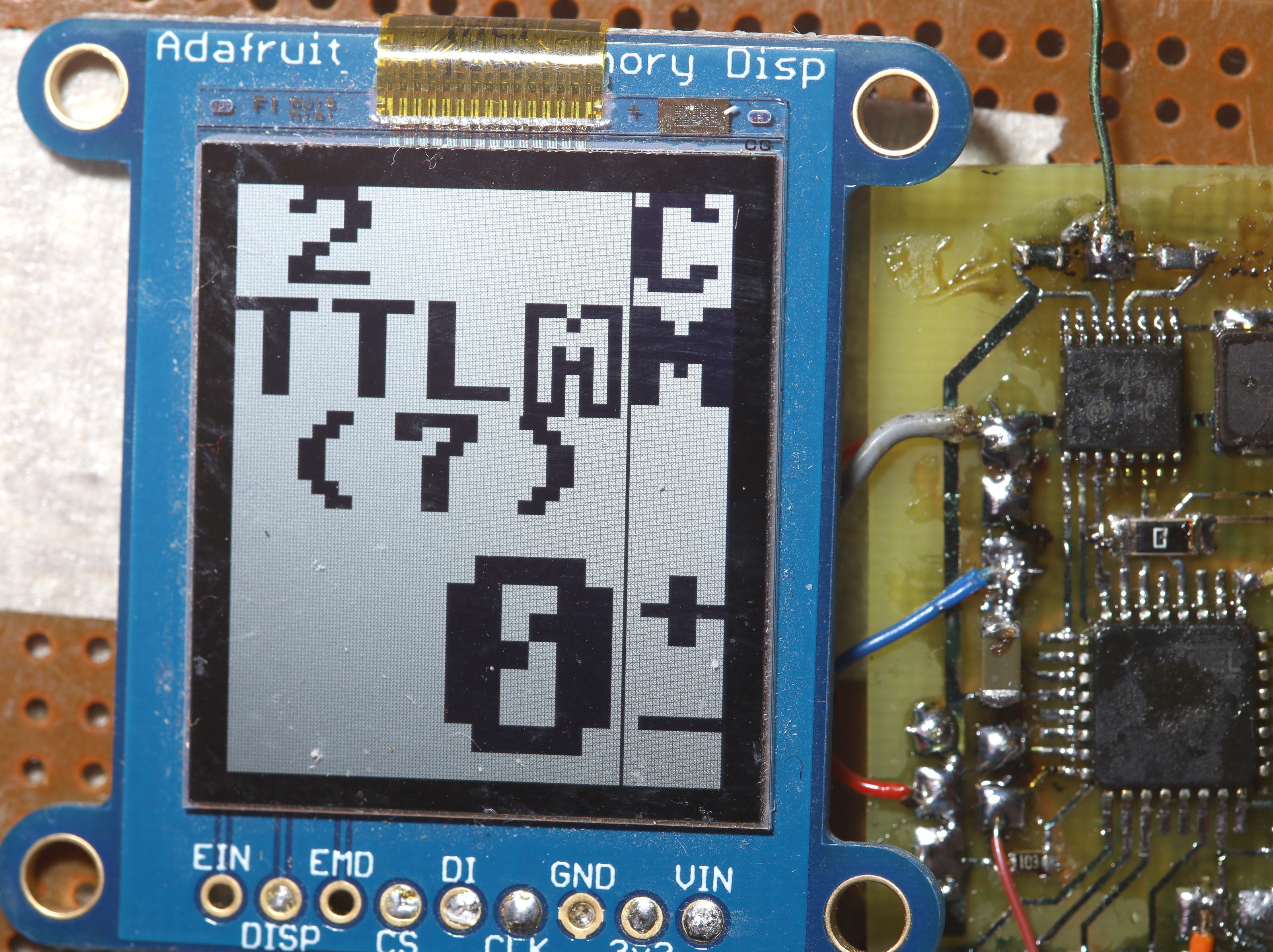
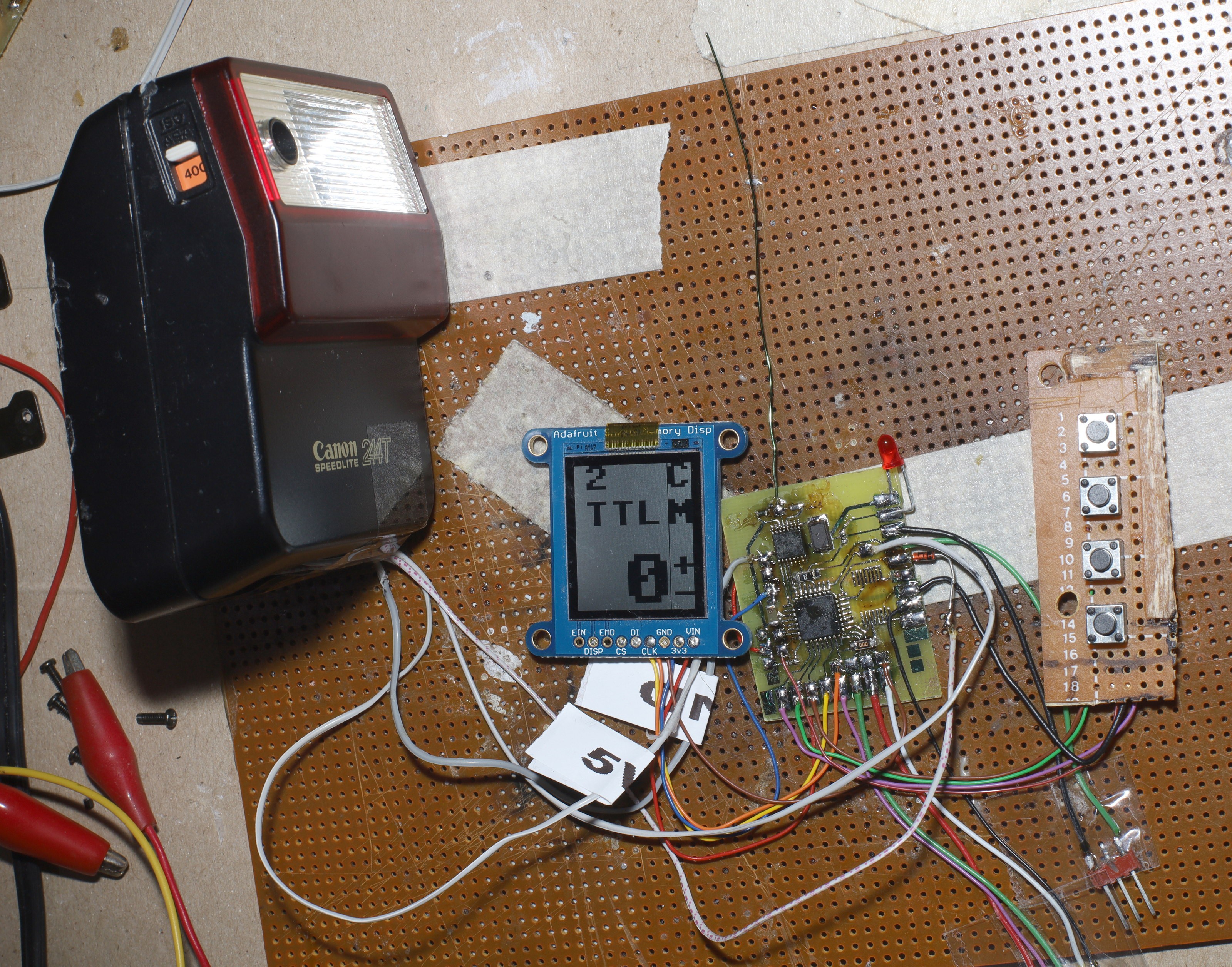
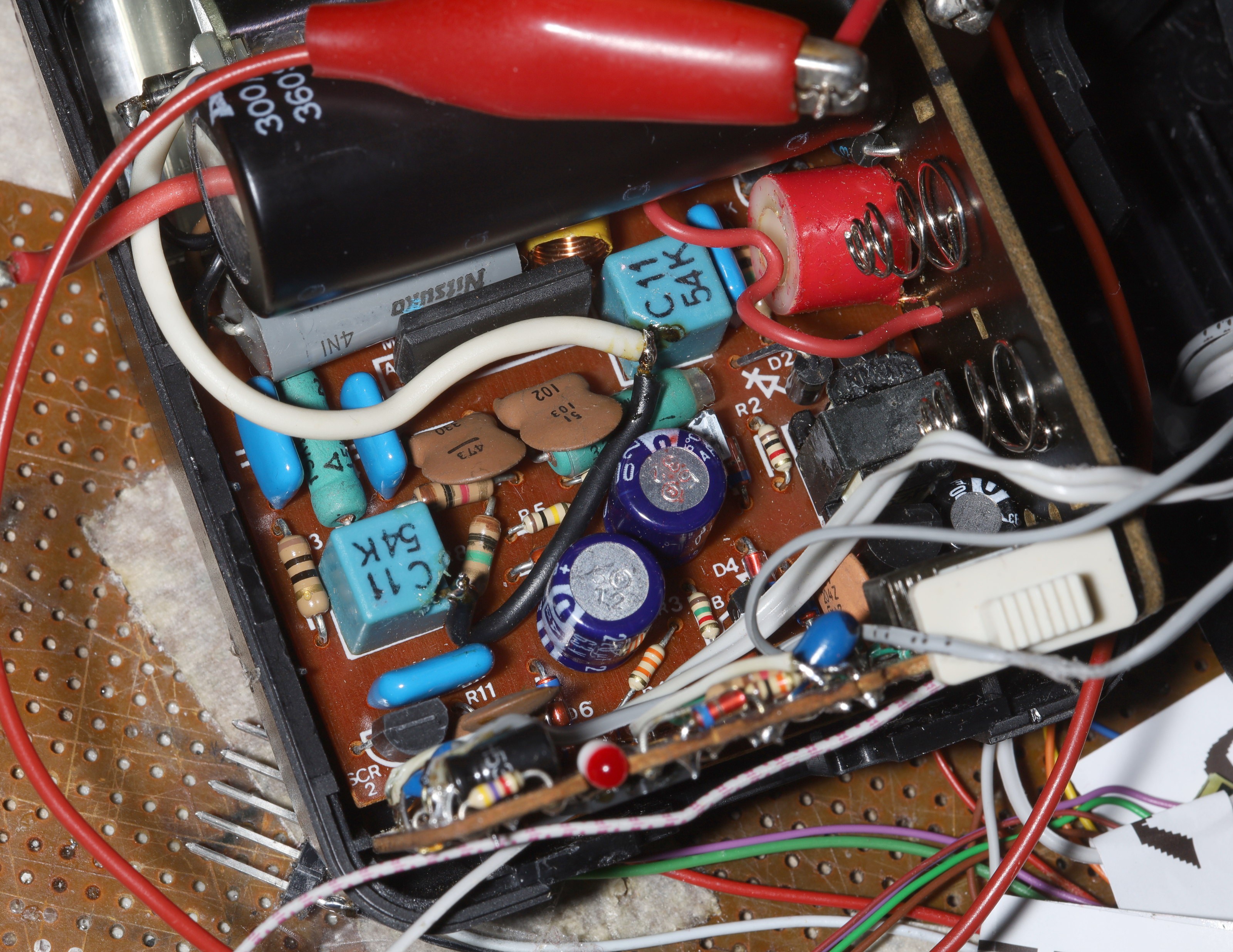
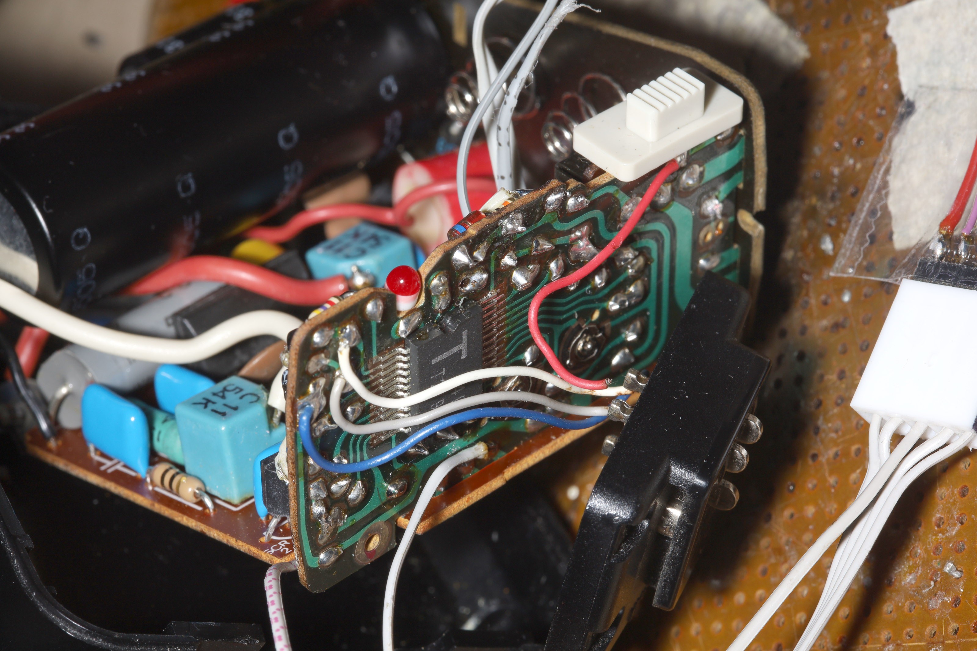
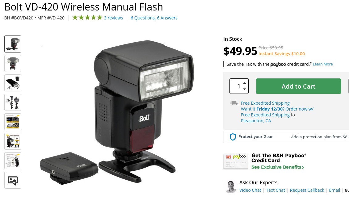
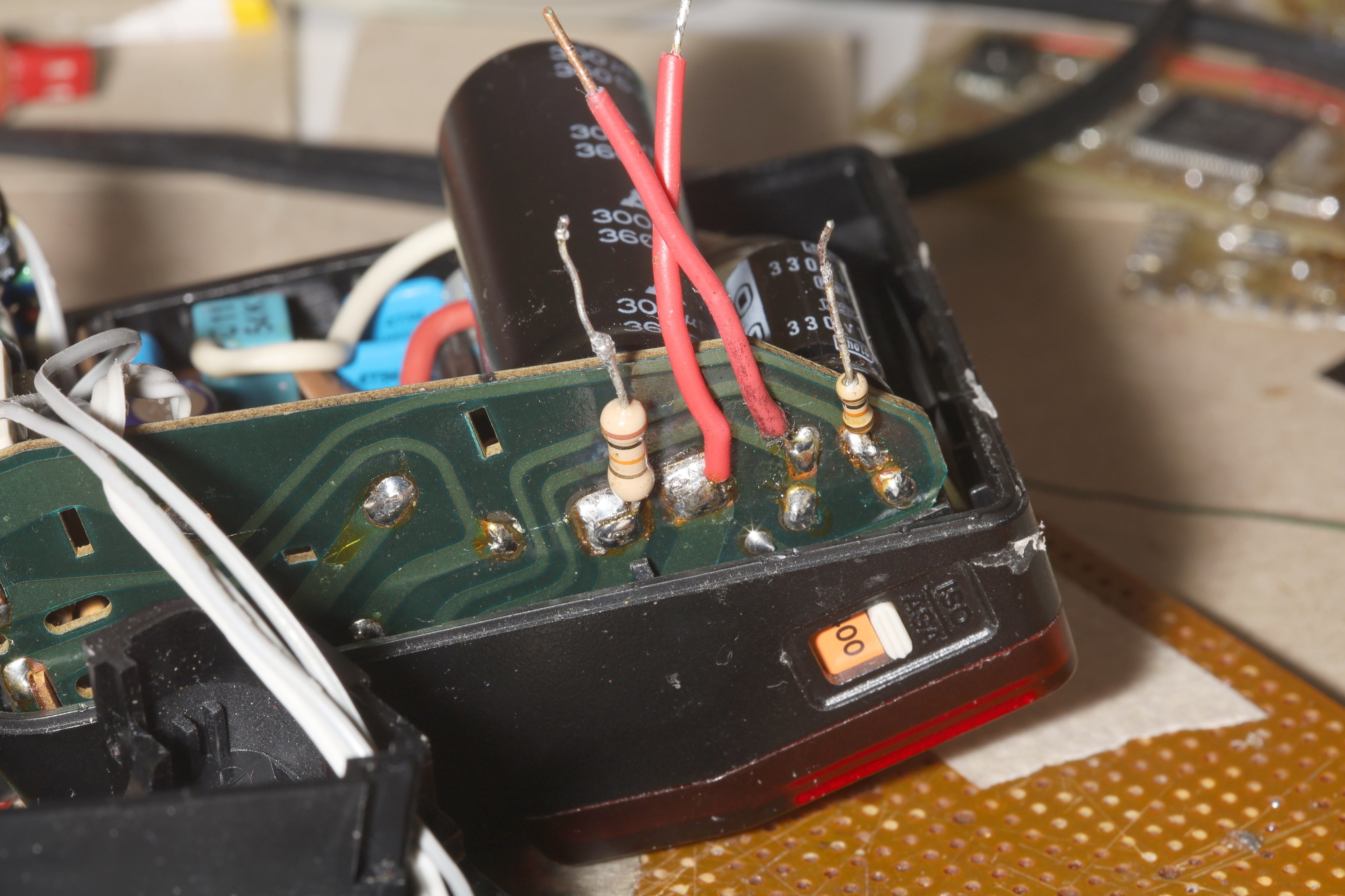
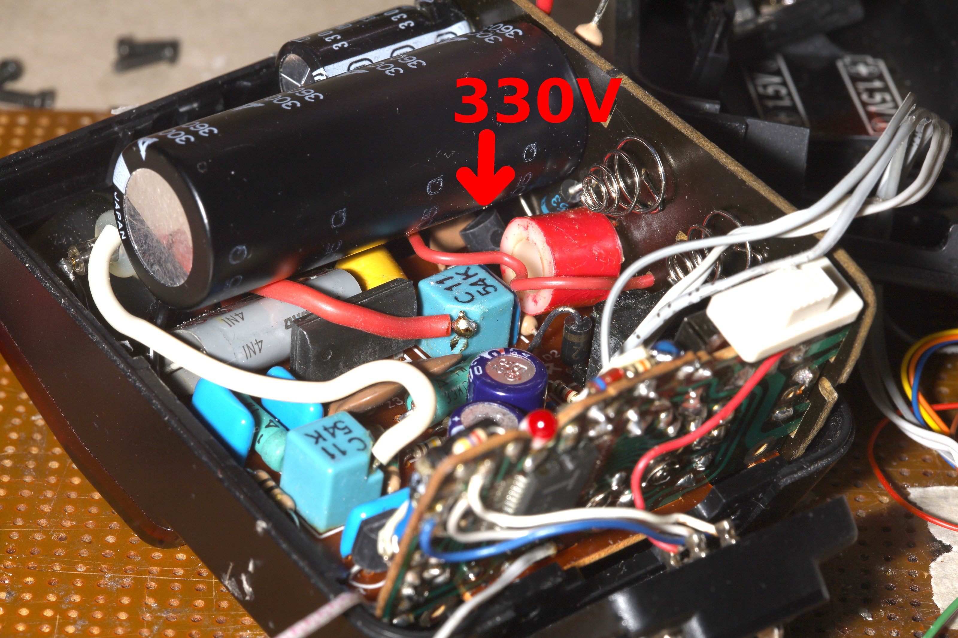
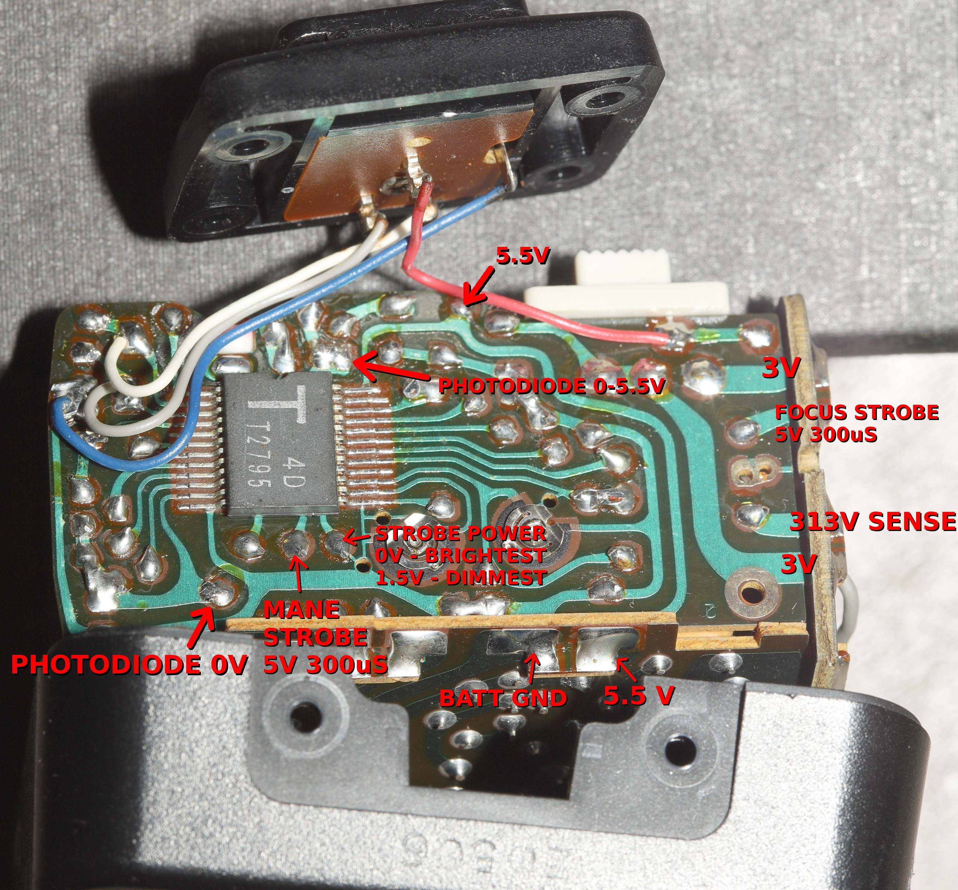
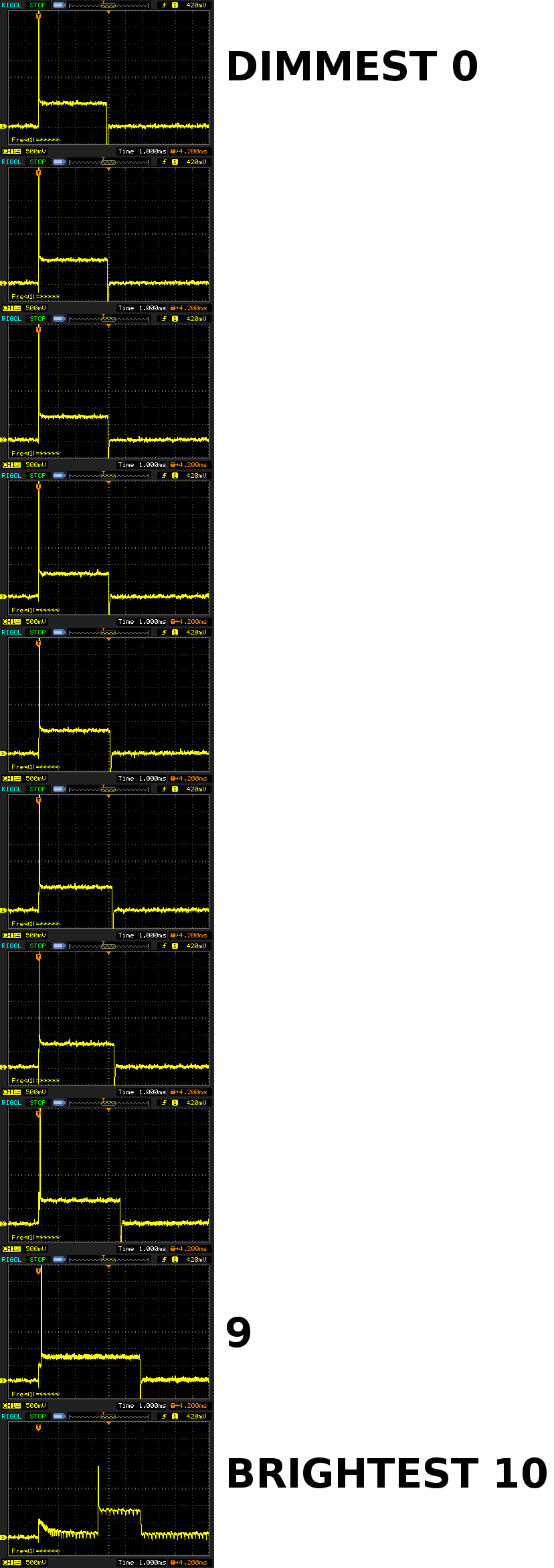
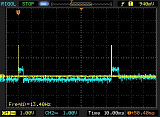
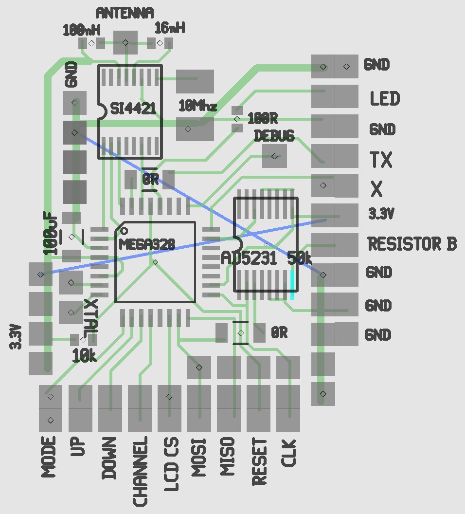
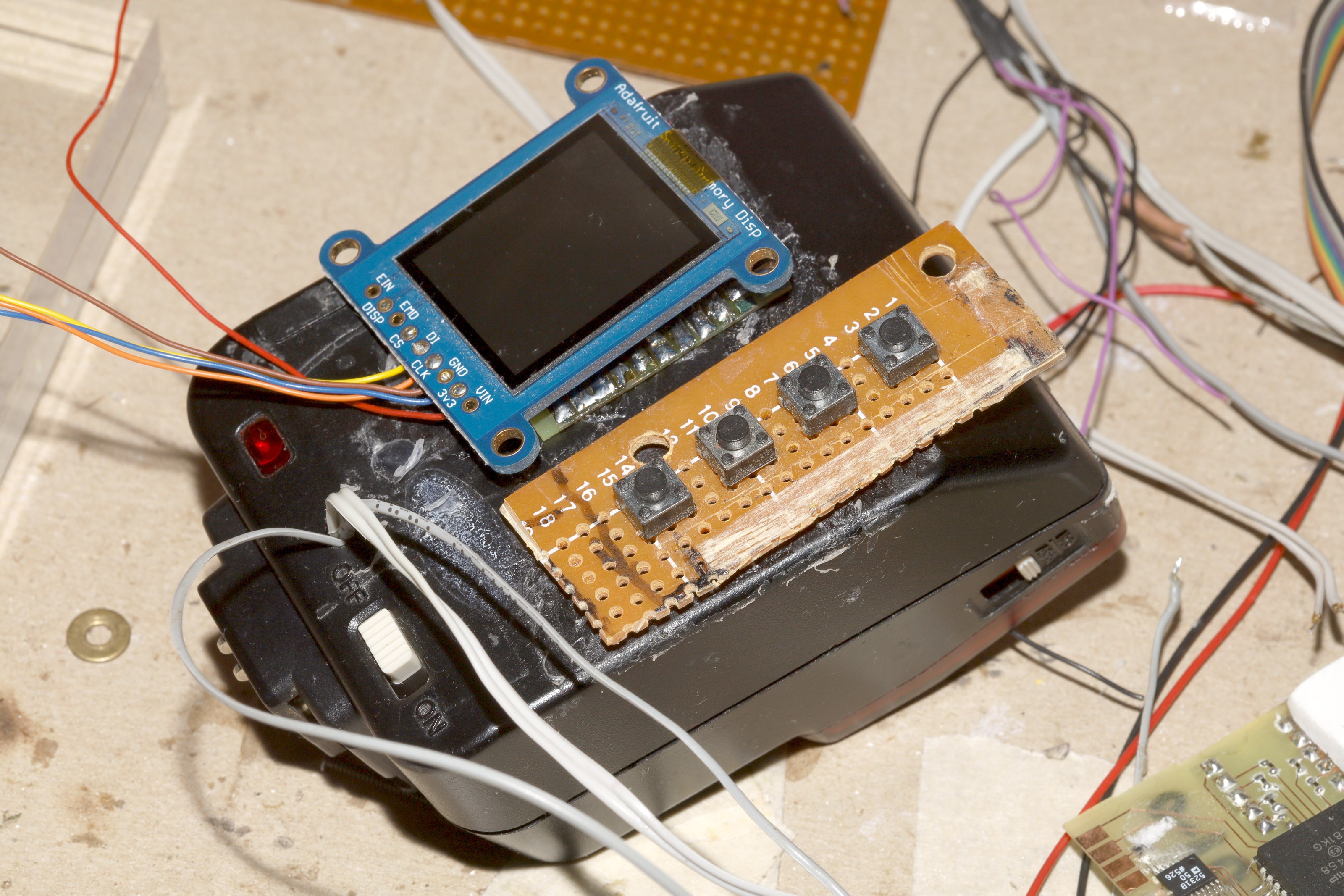
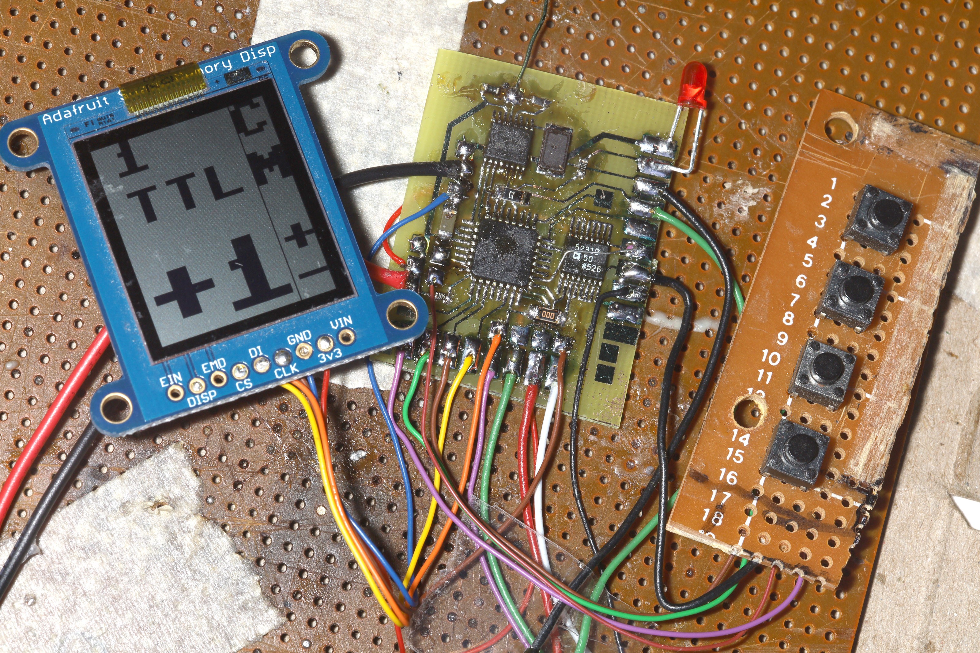
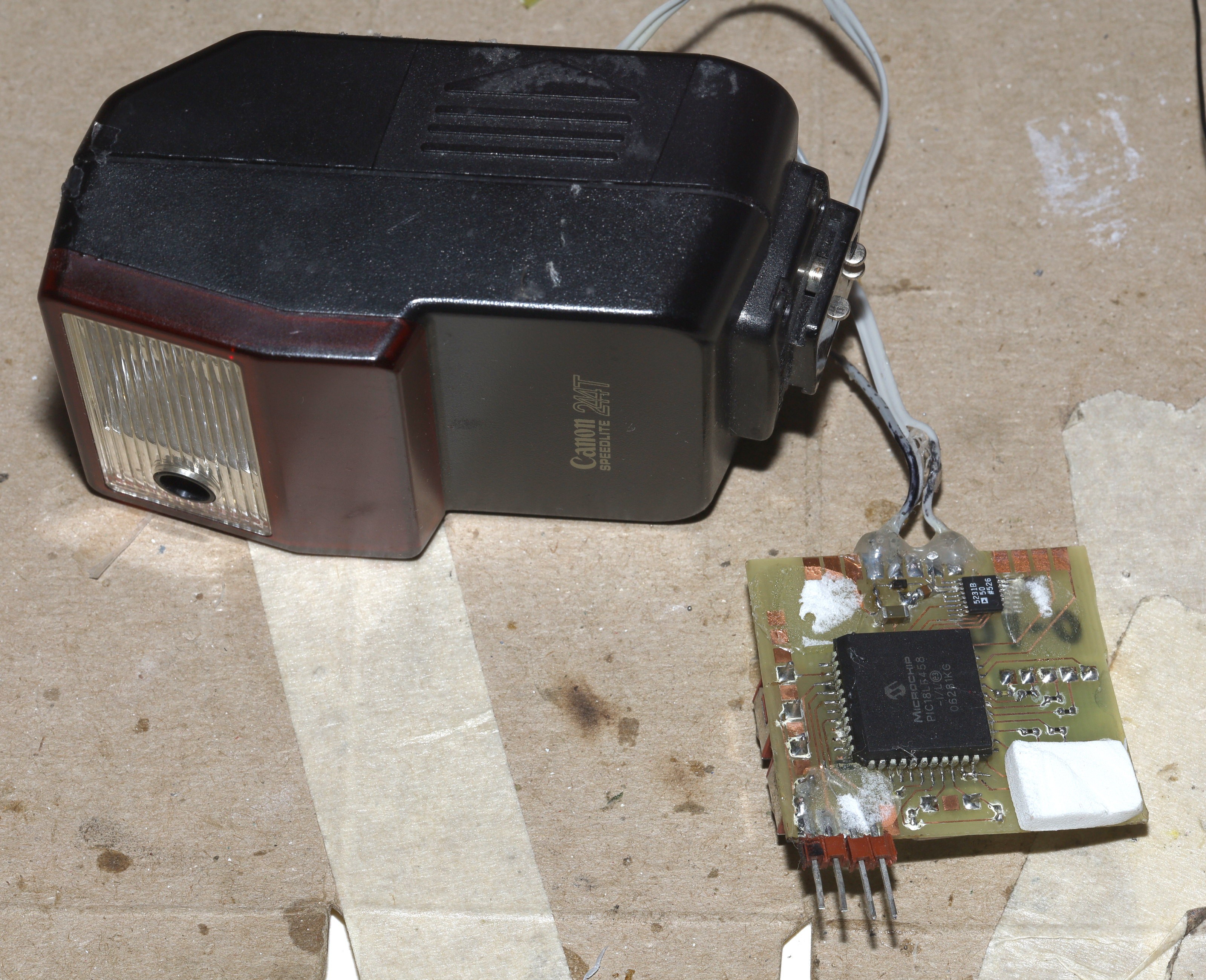
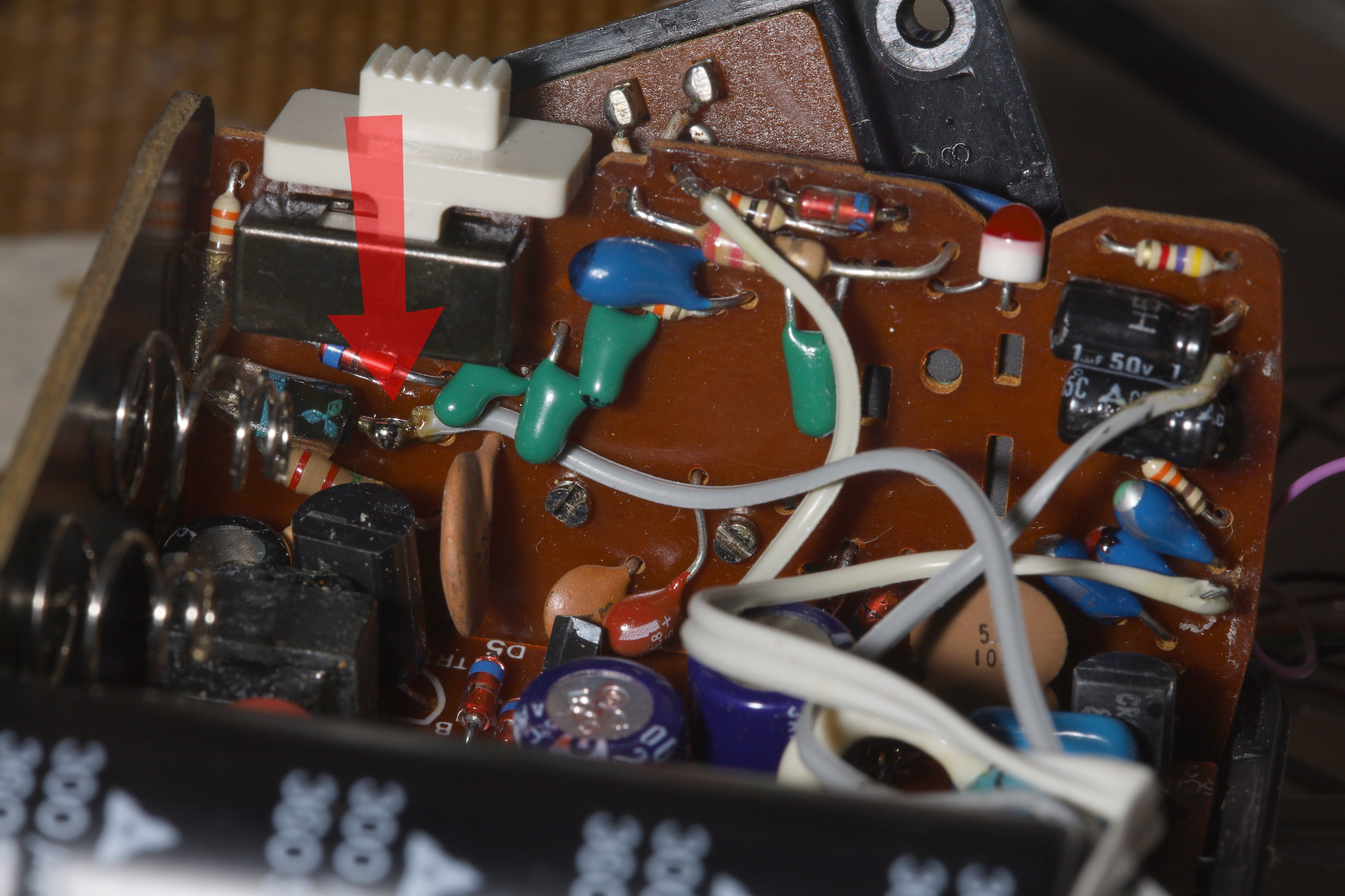
• TTL with double exposures

    lion mclionhead12/31/2022 at 21:32 0 comments

    The best idea was alternating every exposure between preflash & mane flash with an indicator on the LCD showing what stage it was on.  The user would delete every other exposure.  The user could manually take 2 shots in rapid succession to get the same effect as TTL.  Power cycling it or changing mode would reset it to preflash.  It would work on AA's.  It wouldn't have been practical in the film era but it is now.

    It's the dumbest goal a lion ever had, but it's about getting some return on investment.

    The preflash & mane flash states.  Concessions were made with the commodore font to fit enough characters in.  The original reverse characters for M & P weren't as legible.

    To make it more bearable, it shows the power requested by the camera after the preflash.  Even $600 flashes can't do that.  The camera seems to lowball the requested power.  Past experiments showed the camera scale is 8 units per stop, but it seems to either require more stops per unit or rounding.  1 problem is knowing what power to use for the preflash so it has enough room on both sides & doesn't saturate the sensor.


    Digging deeper into the power control issue, there's nothing online about power control in camera flashes.  There's just not a crossover of interest from electronics to photography like there is for oscilloscope teardowns.  

    The power pin goes into pin 4 of an SA01 thyristor array, aux thyristor gate.  Aux thyristor anode goes to a cap connected to the flash tube.  The cap might drain the tube when it's grounded.  Disconnecting the power pin from the original brain didn't change anything.

  • Busted again

    lion mclionhead12/30/2022 at 02:41 0 comments

    Updated the diagram with the signals currently being used & the ever important suicide voltage.

    The rework inside

    Power level was connected directly to the atmega.  Going through a diode or a resistor made no difference.

    Then the rest of the wires were routed through the former hot shoe.  Reassembly will be scotch intensive.

    The next step was a power testing jig.

    You can sort of calibrate it by trying to get the same histogram while doubling ISO values.  Ambient light made the lowest power settings slightly lower than they should be while not affecting the highest power settings.  The trick with reducing ambient light was to move closer to the flash.

    The SCR - POWER delays for each stop were not powers of 2 but somewhat logarithmic.

    0, 24, 32, 50, 70, 100, 170, 300us

    The flash was found to have only 8 stops from dimmest to brightest, giving 0-7 for the manual power settings.  Helas, preflash recycling stopped working most of the time.  When it recycled, it would most often use full power for the mane flash.  There might have been a correlation between battery charge & recycling time, but the erratic full power was a different story.  Power was never erratic in manual mode.

    It was a tragic regression from yesterday.

    Going back to the bench, it was found that TTL recycling worked when battery voltage was 3 & became very unreliable below 2.8V.  It would need a lipo with buck converter.  Power control didn't work at all in TTL mode.  The 2nd firing was either all or nothing.  0us always fired minimum power.  30us was randomly all or nothing.  Sometimes the power pin got stuck high & drained the capacitors until a power cycle.  The same thing was observed when holding power high for over 50ms.  The power pin seemed to treat the TTL recycling as a single firing of over 50ms.

    1 good nugget is it could fire without the pilot light.  It just couldn't hit full power unless the pilot light was on.

    The difficulty with power control in TTL mode is the new deal breaker.  Things once again pivoted towards a scratch built flash with just the tube & reflector being reused.  The science of the SCR latches & high voltage triggering is quite complex.

    The leader in small size seems to be the 270EX II, formerly $120 now $150 bidie bux.

  • TTL recycle achieved

    lion mclionhead12/29/2022 at 03:38 0 comments

    It could recycle faster if the latency was in the SCR's & there were 2 of them connected to the flash tube.  There are 2 SCR's.  The 244T has an IR circuit for autofocus & a visible circuit for the exposure.  They're CR02AM thyristors connected to C1154K's.  C1154K's are transformers which boost the thyristor current to a very high voltage.   The voltage is applied to the tube envelope to fire the flash.

    SCR2 fires the mane flash & was previously labeled MANE STROBE.  SCR1 is buried under the caps & fires the IR flash.  It was previously buzzed out & labeled as FOCUS STROBE.  Testing showed FOCUS STROBE & MANE STROBE could both fire the mane flash with controlled power if either transformer was connected to it.  Unfortunately, if the 2 transformers were connected simultaneously, power was always maximum.  There would have to be a way of connecting 1 at a time.

    Mane flash (white wire) connected to IR flash transformer.  IR flash (red wire) floating.  Mane flash transformer floating.

    Both transformers connected to mane flash.  POWER LEVEL doesn't do the business anymore.  The cathodes of both SCR's are connected to battery GND.  

    Another test showed if only SCR1 is connected, it recycles fast enough to support TTL.  Noted the big green resistor for SCR1 was double the big green resistor for SCR2.  Maybe that affects the recycling time.  Maybe the difference in recycling time reflects a difference in cooldown periods for the tubes.

    It can also fire full power the 2nd time & it has the same sync errors for shutter speeds above 1/200 so the timing is exactly the same as SCR2.  The next step would be calibrating the power values for preflash & mane flash.

    A long exposure caught SCR1 firing the preflash & the mane flash in time.

  • How flashes control brightness

    lion mclionhead12/27/2022 at 21:46 0 comments

    Finally discovered that brightness is adjusted by raising SCR2 1st, then raising STROBE POWER.  The gap between raising SCR2 & raising the STROBE POWER pin determines the brightness.  The shorter the gap, the lower the power.  STROBE POWER can be raised before lowering SCR2.    The lowest power is achieved by raising STROBE POWER 1 instruction after raising SCR2.  The maximum power seems to come from raising STROBE POWER 250us after raising SCR2.  Brightness is thus a function of how long the tube is energized rather than some analog magic.

    STROBE POWER turns off the SCR by probably shorting the mane cap.  It might take time for the mane cap to recharge after that, hence why it can't fire for another 100ms.

    Tried adding an extra pulse to trick it into recycling in under 100ms, but it didn't work.  The length of STROBE POWER or SCR doesn't matter.

    There might be a protocol value which tells the camera the shortest delay between preflash & mane flash.  Finding it is rather hopeless.  It's not polling the flash.  D1 low signifies to the camera that the flash is busy.  Holding the D1 pin low for 100ms during the issuing of the MANE FLASH packet might delay the mane flash enough, but the user would have to configure the camera side for each flash.  Sadly, the camera ignores D1 after a while & fires the mane flash even if it's busy.

    With the power algorithm known, it makes sense to ignore the hotshoe signals, scrap the digital pot & control it directly through the 2 logic signals.  The hotshoe wires broke off anyways.  

    The capacitors are no doubt dried out.  It sucks 250mA to top off the capacitors when it's idle.  There's no plan to continue using it.

    For another flash to convert, the cheapest ones these days don't even have a power adjustment & are not likely to recycle in time.  

    There might be a practical need to hack a vintage one if small size, low cost, & power adjustment are desired.  

    The cheapest variable power ones are gigantic.  They have to be over $60 before becoming compact & variable power for certain brands.

    There's a good chance a TTL one for another brand can recycle in time, but all of that functionality would have to be thrown away to work with Canon.

    TTL for other brands begins at $50 but for Canon begins at $150 & it's bulky.

    There's definitely a case for hacking a vintage flash for low cost, small size, wireless, & manual power control, even if it's not fast enough for TTL.  There's just never been a use for a manual flash.

    As far as making a night club effect or a really bright light bulb out of it, the flash tube has a limited lifespan.  

  • Busted

    lion mclionhead12/26/2022 at 09:43 0 comments

    So the flash fires when X is below 3.7V.  The atmega's snubber diode manages to bring X to 3.7V when set as an input.  That gets it to fire on command, but the flash doesn't fire again until X is above 3.9V.  It has hysteresis.  A 2nd diode manages to bring X to 3.9V when set as an input.  That got manual firing to work over wireless.  It synchronizes up to 1/200 but no faster.  That may be a limitation of the atmega's interrupt handler, but there's a bigger problem.

    The mane problem is with TTL firing, the flash refuses to fire a 2nd time in under 50ms.  The pilot light goes out on the 2nd firing & it never comes back on.  It has to be powered down until completely discharged, then powered on again to fire again.  The power level doesn't matter.  

    If it just fires the preflash, the pilot light stays on & it can fire again.  Continuous shooting mode works.  It happily fires every time for continuous shooting & the camera slows down when it detects the flash.  It's the 50ms delayed flash which kills it.  It's some kind of lockup in the flash brain.

    2nd curtain sync could lengthen the delay enough to get it to fire, but there's going to be blurring from the long exposure required.  The minimum delay for it to fire twice was probed to be 100-150ms, so that would mean a 1/10 exposure.  It would really need a camera firmware change to space the TTL strobes out more.

    Finding a lower level signal to fire it would be the next task, so probed the 3 mane TO-92's.  

    Capacitor draining resistors were reinstalled & the lion managed to not get shocked.  Very important that the big capacitor gets a higher wattage resistor.

    SCR2 base is the trigger.  Its base goes to 5V for 250us for every trigger.  TR1 is the flyback transistor & has a constant base voltage.  A 3rd transistor under the capacitors has a constant 330V on what looked like a base.   The other active packages showed a constant 60V on what looked like a base.  SCR2 base is fed by a diode from the brain.  Any current to SCR2 base fires it at full power, regardless of duration.

    The lion of 2 years ago was a lot more thorough than remembered & documented not just the mane trigger but how power is determined.  

    https://hackaday.io/project/173855-rehabilitate-a-40-year-old-flash/details

    SCR2 base goes to MANE STROBE.  It seems any current to STROBE POWER causes the mane capacitors to drain, so it was pulsed.  There were some notes about STROBE POWER being pulsed during the firing to control brightness, but not giving consistent results.

    A new probing of STROBE POWER being driven by the flash's brain showed a correlation between pulse width & power, but not an analog voltage.   It's 4ms when dimmest & 6ms when brightest.  It never got above .7V.

    A few tests driving STROBE POWER with the atmega for 4ms - 6ms gave minimum power for all durations.  At least it's possible to set minimum & maximum power, but nothing in between.  STROBE POWER never got over 1V when driven by the atmega.

    Pulsing STROBE POWER over 50ms made it randomly lock up high, drain the capacitor, & never relight the pilot light.  This might have been related to the failures when driving X in TTL mode.

    SCR2 base & STROBE POWER shown during a TTL sequence.

    When SCR2 was driven in TTL mode, the flash continued to only fire once in a 50ms timespan but it never locked up.  The flash alternated between taking the 1st & 2nd pulse of SCR2 but never fired both pulses in the same exposure.  

    There's an implication of a repeating pattern of fire, skip, delay, skip, fire, delay, fire, skip, delay skip, fire but without knowing where in the pattern it is, there's no way to add extra pulses to force it to fire at the right time.  It would take a lot of probing to find a voltage that correlated...

    Read more »

  • Mane board

    lion mclionhead12/23/2022 at 04:59 0 comments

    The Adafruit memory display https://www.adafruit.com/product/3502 was a ridiculous board, a giant board just dedicated to shifting the logic levels & regulating the voltage for a tiny display.  It's mane advantage is a 300mA voltage regulator suitable for powering the entire project.

    Reviewing the flash rehabilitation https://hackaday.io/project/173855-rehabilitate-a-40-year-old-flash RESISTOR B has a voltage from 0 - 2.5 but is connected to a resistor inside the flash.  It therefore has to be connected to an adjustable resistor rather than a DAC to see the right voltage.

    AVCC has to be connected for PORTC to work.

    Mock up.

    The display shows its 1st dynamic data since it was bought 5 years ago.  They don't make them like this anymore.

    The only way to fit any graphics in the atmega328 was to calculate each pixel in place & scale up a commodore 64 font file.  The font was enlarged 8x to get the biggest characters & 4x to get the small characters.  It undoubtedly would look less like an atari 2600 & more like a macbook if the atmega had more memory.  The commodore 64 characters took 152 bytes.  Storing 1:1 characters would take 7040 bytes.  Maybe it would fit, but it wouldn't be nostalgic.

  • Finding X

    lion mclionhead12/22/2022 at 06:04 0 comments

    Previously on flash hacking, the 244T gained a manual setting to make it minimally functional on a modern camera.  This ended up quite useless.  Lions just never mess around with manual exposure.

    The original flash has only X, ID, & D1 data from flash exposed.  Presumably high ID caused it to light its IR emitter for an exposure calculation.  Grounding X fires it.  It sent a code out on D1 to set the camera's aperture.  The original flash had a built in photocell & a filter to try to compute its own power level.  The filter was lowered over the photocell by a very clicky switch.  That was ETTL in 1984.  There was no way every camera since then would continue supporting the funky way this flash controlled exposure.

    The 244T previously had GND, 6V, & RESISTOR B brought out to achieve manual control.  RESISTOR B goes from 2.6 V at minimum power to 0V at full power.  There's a table in flash_pot.s which converts resistances to linear steps in power.

    The next step is to expose X to fire it.  It needs a radio receiver for use with the wireless flash transmitter.  It's much more practical than going in through the hot shoe.  It won't be too high off the lens.  The hot shoe will never be used again.  The camera hot shoe will be covered by the radio transmitter.

    The mane question is whether to support a manual mode & exposure compensation.  It would entail an LCD & 3 buttons: mode, up, down.  It could see a lot of use as wireless TTL, in which case those functions would be essential.  It may continue seeing no use, in which case those functions would be useless.  Wireless functionality & manual mode could make it useful as a background light in combination with the 580EX-II.  

    X was connected to a 330R resistor & diode behind some dipped tantalums.  This must have been input protection against whatever someone put against the X pin.  The capacitor budget spared no expense in 1984 Japan.  Sadly, the plastic tabs have all perished.  It might need a PLA enclosure or an extreme case of scotch one day.