 lion mclionhead
So the flash fires when X is below 3.7V. The atmega's snubber diode manages to bring X to 3.7V when set as an input. That gets it to fire on command, but the flash doesn't fire again until X is above 3.9V. It has hysteresis. A 2nd diode manages to bring X to 3.9V when set as an input. That got manual firing to work over wireless. It synchronizes up to 1/200 but no faster. That may be a limitation of the atmega's interrupt handler, but there's a bigger problem.
The mane problem is with TTL firing, the flash refuses to fire a 2nd time in under 50ms. The pilot light goes out on the 2nd firing & it never comes back on. It has to be powered down until completely discharged, then powered on again to fire again. The power level doesn't matter.
If it just fires the preflash, the pilot light stays on & it can fire again. Continuous shooting mode works. It happily fires every time for continuous shooting & the camera slows down when it detects the flash. It's the 50ms delayed flash which kills it. It's some kind of lockup in the flash brain.
2nd curtain sync could lengthen the delay enough to get it to fire, but there's going to be blurring from the long exposure required. The minimum delay for it to fire twice was probed to be 100-150ms, so that would mean a 1/10 exposure. It would really need a camera firmware change to space the TTL strobes out more.
Finding a lower level signal to fire it would be the next task, so probed the 3 mane TO-92's.
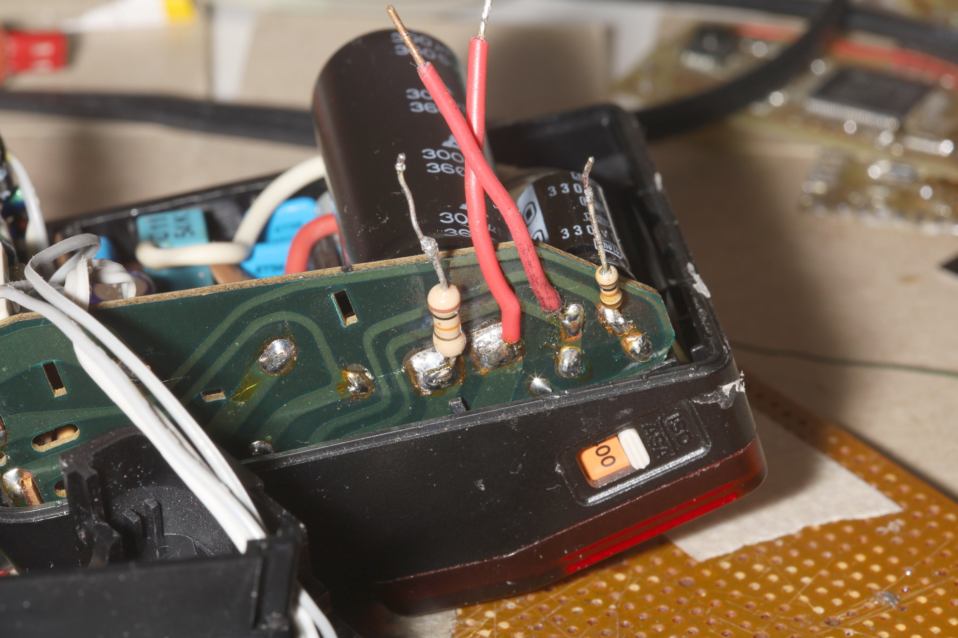
Capacitor draining resistors were reinstalled & the lion managed to not get shocked. Very important that the big capacitor gets a higher wattage resistor.

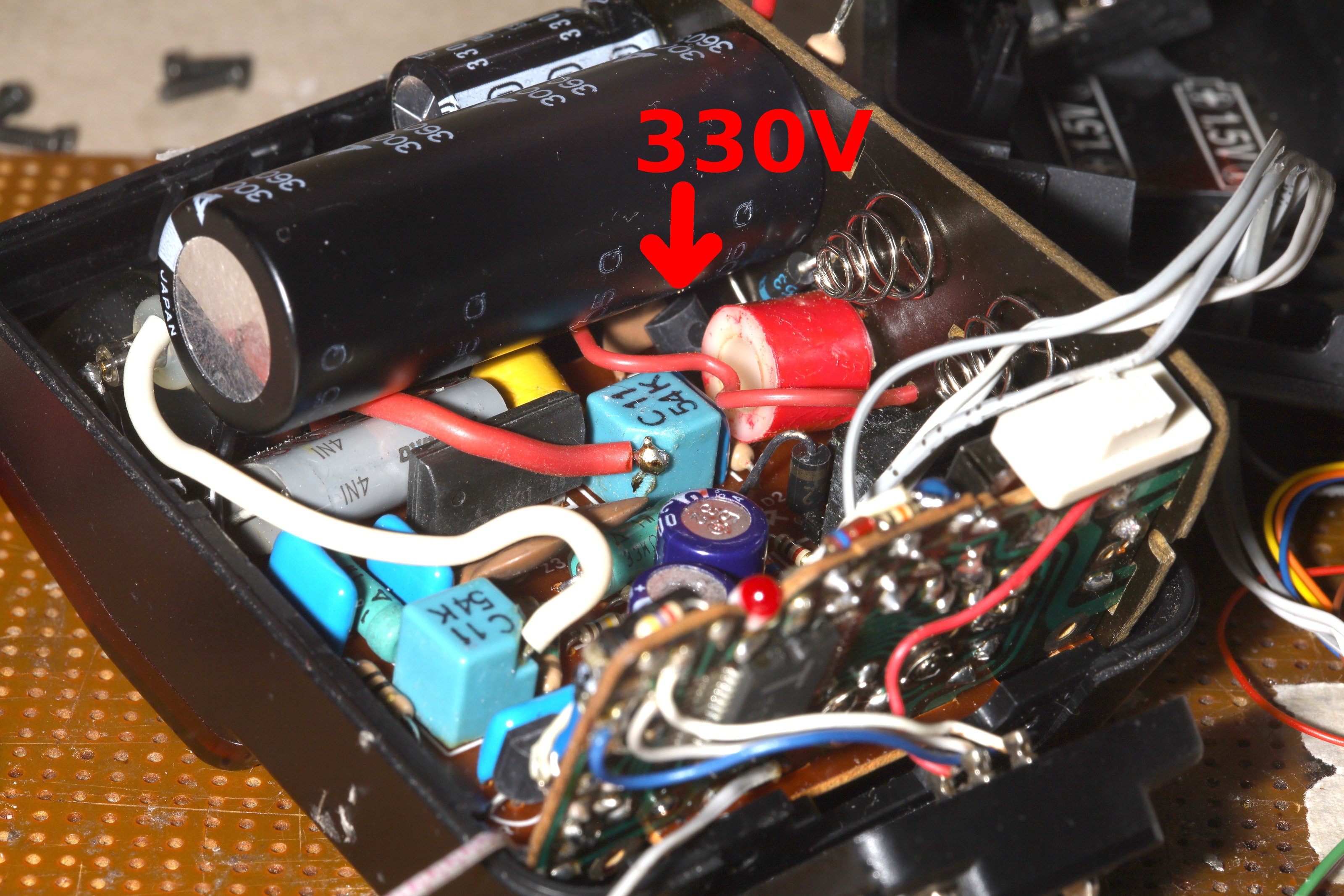
SCR2 base is the trigger. Its base goes to 5V for 250us for every trigger. TR1 is the flyback transistor & has a constant base voltage. A 3rd transistor under the capacitors has a constant 330V on what looked like a base. The other active packages showed a constant 60V on what looked like a base. SCR2 base is fed by a diode from the brain. Any current to SCR2 base fires it at full power, regardless of duration.
The lion of 2 years ago was a lot more thorough than remembered & documented not just the mane trigger but how power is determined.
https://hackaday.io/project/173855-rehabilitate-a-40-year-old-flash/details
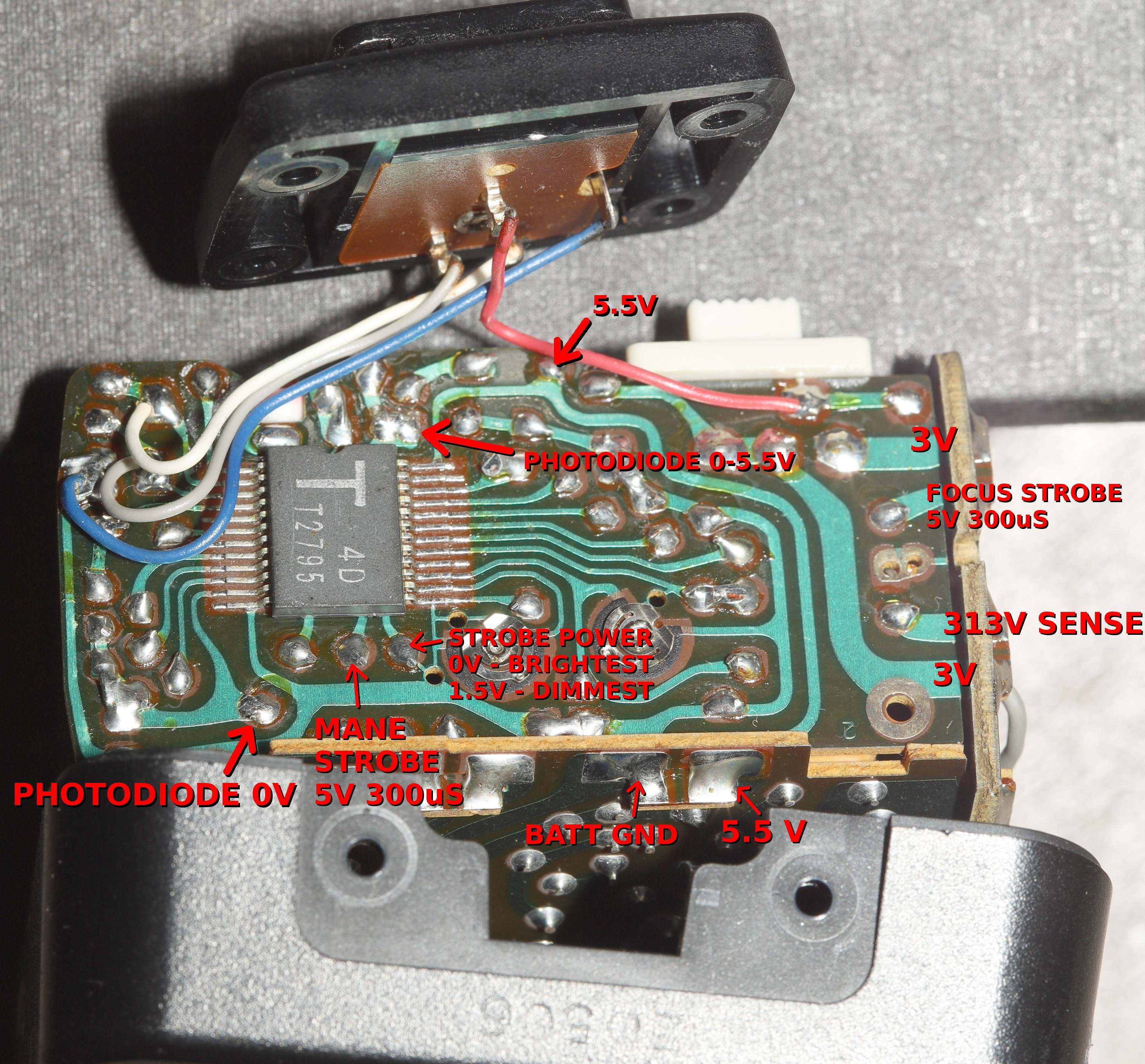
SCR2 base goes to MANE STROBE. It seems any current to STROBE POWER causes the mane capacitors to drain, so it was pulsed. There were some notes about STROBE POWER being pulsed during the firing to control brightness, but not giving consistent results.
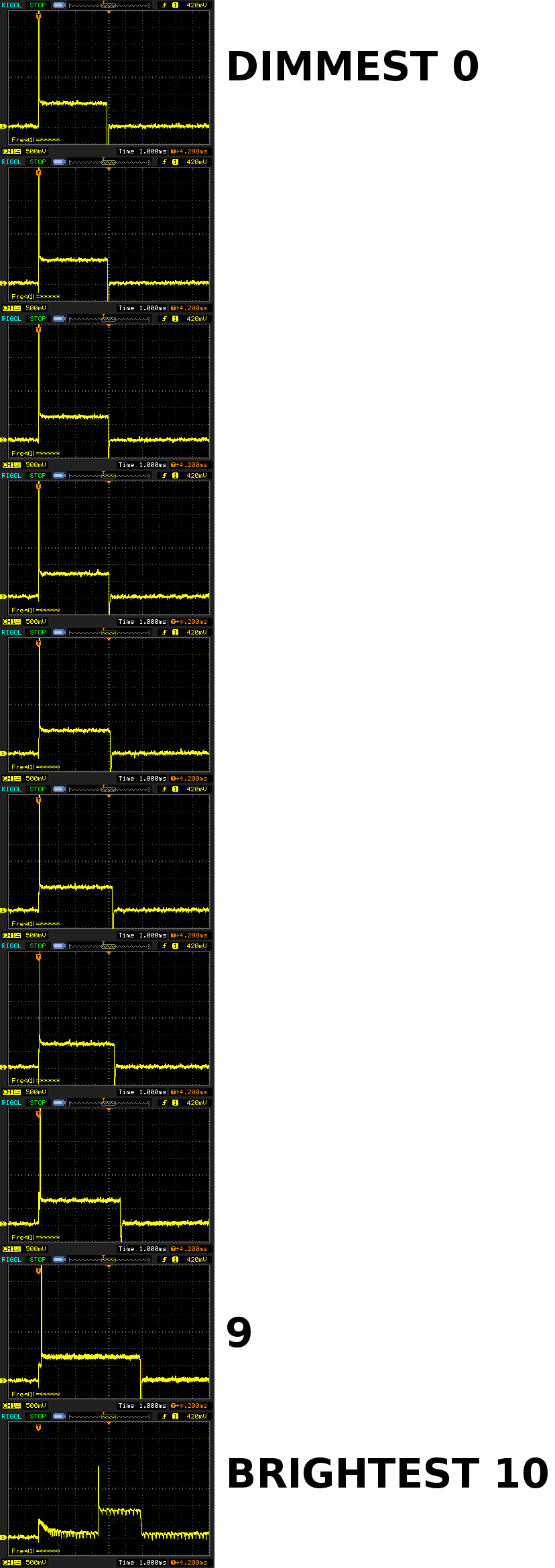
A new probing of STROBE POWER being driven by the flash's brain showed a correlation between pulse width & power, but not an analog voltage. It's 4ms when dimmest & 6ms when brightest. It never got above .7V.
A few tests driving STROBE POWER with the atmega for 4ms - 6ms gave minimum power for all durations. At least it's possible to set minimum & maximum power, but nothing in between. STROBE POWER never got over 1V when driven by the atmega.
Pulsing STROBE POWER over 50ms made it randomly lock up high, drain the capacitor, & never relight the pilot light. This might have been related to the failures when driving X in TTL mode.
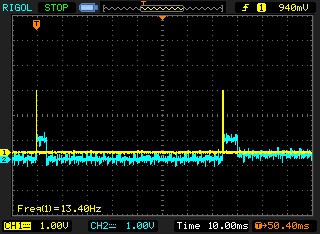
SCR2 base & STROBE POWER shown during a TTL sequence.
When SCR2 was driven in TTL mode, the flash continued to only fire once in a 50ms timespan but it never locked up. The flash alternated between taking the 1st & 2nd pulse of SCR2 but never fired both pulses in the same exposure.
There's an implication of a repeating pattern of fire, skip, delay, skip, fire, delay, fire, skip, delay skip, fire but without knowing where in the pattern it is, there's no way to add extra pulses to force it to fire at the right time. It would take a lot of probing to find a voltage that correlated with the pattern phase. The pattern does get generated by the delay size, so extra pulses may just cause it to fire, skip, skip, skip, until the next delay.
Another idea is to just fire the preflash, skip the mane flash & throw away the exposure. On the next exposure, skip the preflash & fire the mane flash using the last TTL derived power. It entails downloading a lot of blank exposures & requires showing the user where in the pattern it is.

Lacking a high speed videocam, a long exposure while panning a still cam revealed only 1 firing during a TTL exposure. Testing confirmed it fired every time in manual mode with the longer spacing. Low level firing was now busted & so was the idea of converting the 244T to TTL.
After that long effort, the lion kingdom went out to face the world again, wiser. It might be easier to build a flash from scratch. Going any deeper with the 244T would entail building a new circuit for it & scrapping the vintage circuit. The vintage active parts may not be fast enough to do the job.
What would definitely work is strapping 2 vintage flashes together & firing them in succession. The same flash tube could be shared by both.
It might be more productive to hack a strobe. A modern manual flash may be hackable, since the high voltage parts can't go on a SOC.
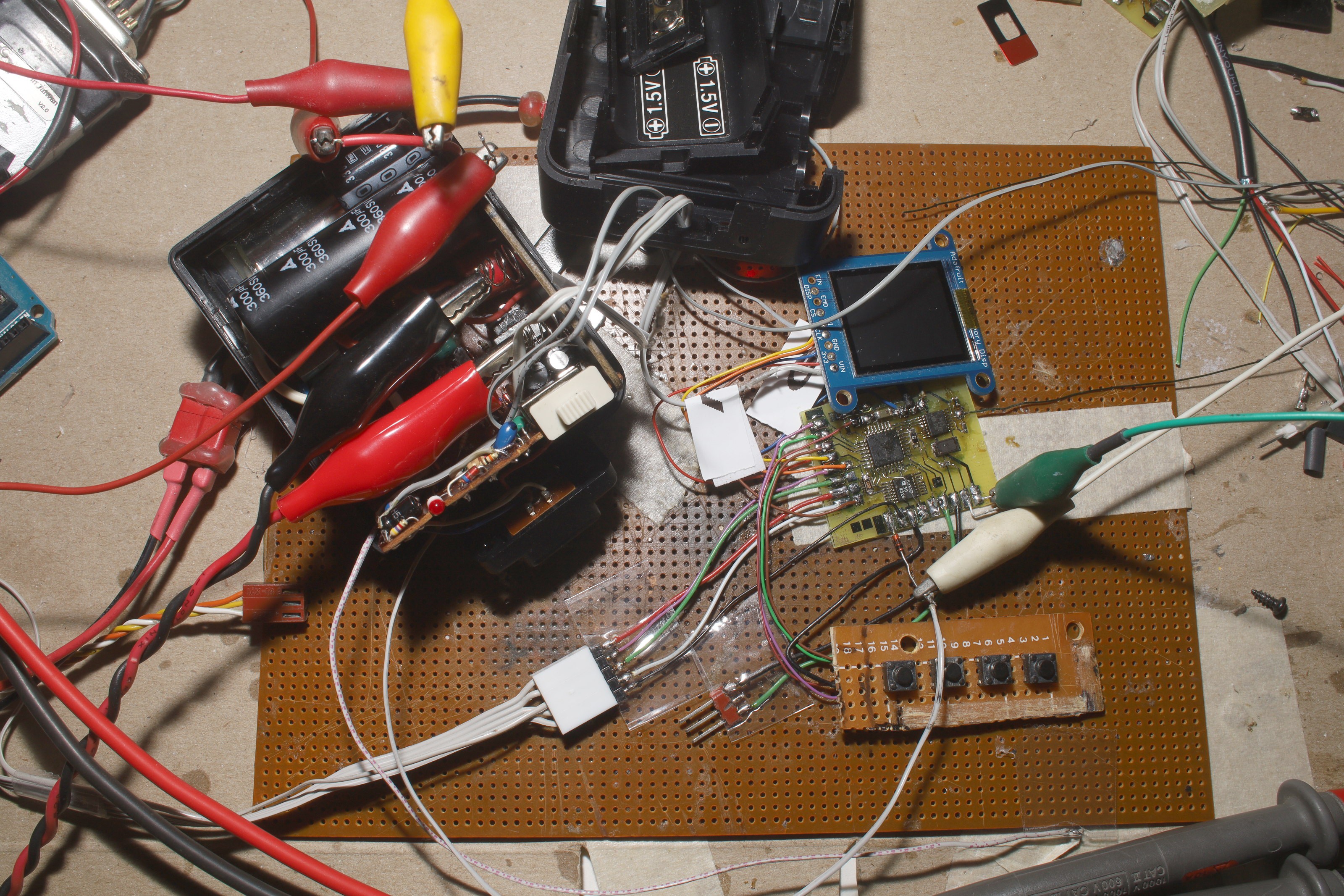
The existing circuit could be kept around just for manual mode, but manual mode has never been useful. It would be better off with a pot in place of the LCD. The LED would blink the channel. The LCD is more compact though. The test setup was buried in the gadget graveyard along with the embedded oscilloscope & the embedded serial console.
Discussions
Become a Hackaday.io Member
Create an account to leave a comment. Already have an account? Log In.