 Adrian Studer
A while ago I built the NeoPixel Punk Console, a circuit for controlling NeoPixel RGB LEDs with just 555 timers and a handful of 74-series logic chips. That project did achieve its goal, but the light patterns were very blinky, mainly restricted to primary colors and hard to control.
The NeoPixel Theremin seeks to offer a smoother visual experience, while staying true to the "No MCU" premise.
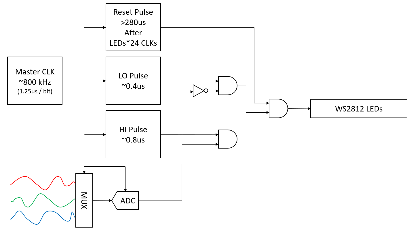
The main issue with the NeoPixel Punk Console is, that its circuit is generating data bits without regard for the RGB data structure the LED string is expecting. To solve that, we will need:
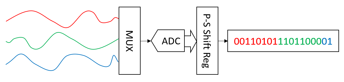
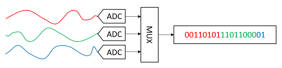
- a MUX that switches between 3 analog signals for R, G and B
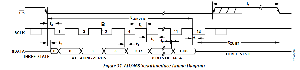
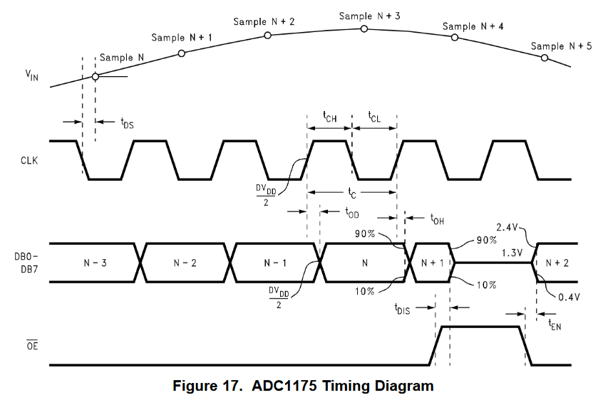
- an ADC that translates the analog signal to digital bits
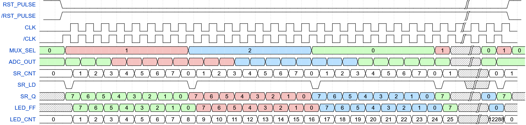
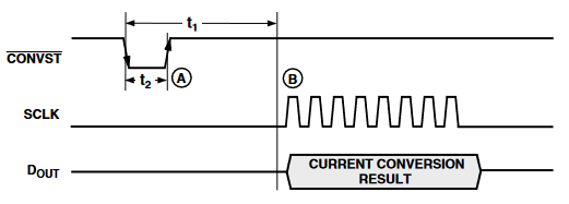
- some logic to keep the above in lockstep with the stream of pulses sent to the LED string
Reusing the 555-based LED driver logic, the new system diagram looks like this:
.. work in progress
 Paul
Paul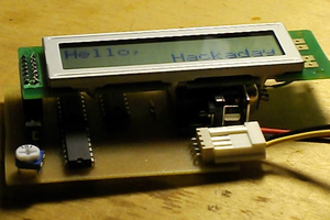
 Steve Michel