The difference between this circuit and other similar projects is that this project does use the TxD pin of the COM port and it does not require any complex IC. All other projects that I found either use programmed microcontrollers or bit bang the meta signals (DTR or RTS) of the serial port. With this circuit you simply send the data to serial port.
The circuit consists of two 555 timers. The Start bit of the TxD signal of the serial port triggers the first 555 in monostable mode (byte timer). The output of the byte timer enables the second 555 (bit timer) by disabling its ~reset signal. The bit timer then generates the clock for the asynchronous TxD data to be stored in the shift register. At the end of the timing period the byte timer stops the bit timer by enabling the ~reset of the bit timer so that the bit timer generates exactly 9 clock pulses: 1 Start bit + 8 data bits. At the same time the byte timer output (the end of the timing period) enables the strobe signal of the shift register. The 9th clock pulse shifts the 8th data bit into the shift register and at the same time it shifts the Start bit out of the shift register before the strobe signal puts the internal contents of the shift register to the output pins of the IC. The byte length and bit clock frequency are fixed and pre-defined by used parts for the monostable and astable 555 timer respectively. The circuit was successfully tested at 9600 bit/s.
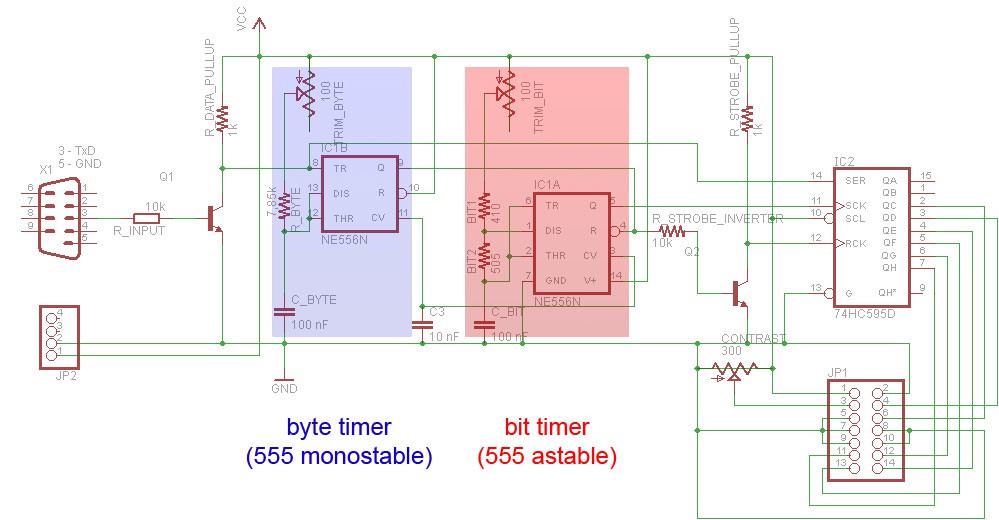
Please right-click the above image and select "View image" to see the schematics.
Timing diagram:
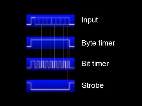
- The Start bit of the asynchronous data (serial port TxD) triggers the Byte timer
- The Byte timer starts the Bit timer
- The Bit timer generates clock pulses that shift the asynchronous TxD data into the shift register
- The Byte timer stops the Bit timer
- The Byte timer generates strobe signal for the shift register
The red lines in the timing diagram represent important delays:
- The byte timer period must end before the bit timer generates 10th clock pulse rising edge
- The shift register strobe must follow the rising edge of the last bit clock pulse
Please note that this circuit exploits the charasteristic of the 555 astable mode - the first pulse (time high) is longer than the following pulses as the timing capacitor must charge from 0 V to 2/3 Vcc but for the rest of the operation it has to charge only from 1/3 Vcc to 2/3 Vcc. This provides the important delay of the clock pulses for the shift register without additional circuitry.
The shift register stores and outputs the byte, the NPN transistors invert the signals as needed and at the bottom right corner of the schematics, there's a pin header to connect a HD44780 LCD display that can be driven by special serial data (HD44780 data and commands are converted in software to the waveforms for the HD44780 input pins). I wrote a simple C program to control the LCD and output texts to it and later a small Windows utility to show IP address and CPU load on the attached LCD.


 Артём Шакиров
 Jac Goudsmit
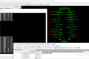
 zpekic
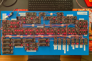
 Joël de Kanter
It’s a really clever solution like zpekic said.
What about skyrocketing your protocol and try to improve the baudrate of your schematics ? Or make it serial to parallel without the LCD by adding pin or a small flat ribbon cable ?
Have a nice day !