Anders Nielsen
-
Crossover episode!
04/10/2024 at 08:45 • 0 commentsSo what's going on with the #65uino at the moment? Nothing?
Actually, quite a lot! I'm using it as the prototyping platform for my #Relatively Universal ROM Programmer and wow do I have news about that.
I've written the 6502 assembly code to program Winbond W27C512's, which are some of the newer-ish ROMs, electrically erasable and all that jazz - as well as the 2732A's which are a bit older, requiring UV-C for erasure and 21 Volts for programming.Either way, successful proof of concept and I now have PCB shields coming from a manufacturer - oh how I hope they work.
-
I'm giving away 25 8-bit motherboards!
11/17/2023 at 13:06 • 0 comments...is the title of my new video. And that doesn't make it any less true :)
I got a sponsorship for a bunch of #65uino boards with the SMD components presoldered, 3v3 and 5V regulators, inverter, 1 MHz oscillator, LEDs, USB and passives, so you only have to solder(and source) the pinheaders and DIP-packages (or sockets might be more appropriate).
I hope this'll get some 65uino-boards into more hands before the holidays next month :D -
Making a 6502 VT100 Terminal (?)
11/11/2023 at 20:35 • 0 commentsTechnically I might be redoing a lot of things that have been done before - some of them poorly even - but I like to learn new things and I don't mind sharing what I learned, even if it does sometimes expose my cluelessness :)
My last two videos on the #65uino project has focused on making it a bit more friendly as an old school computer terminal - and I used an old Raspberry Pi Zero W as an example of something that'll spit out VT100/ANSI compatible serial text, since I don't have a mainframe lying around to connect to.
I considered it a bit of a side quest, since I'd rather code Flappy Bird or something like it for the 65uino, but I got in the awkward situation of starting something I didn't want to leave hanging mid air.
I think I managed to round it off a bit after going through what hardware and software flow control is for serial data, but if I find an easy way of implementing a few more control codes I might go for it and expand a bit further..
Either way - I'm certainly not any kind of done with the 65uino.
-
Can a 6502 control a Raspberry Pi?
09/26/2023 at 08:21 • 0 commentsYes - oh so absolutely. Though you might have to teach the 6502 a bit of good serial terminal manners.
In my new #65uino video I go through what it takes to make it act (almost) like a computer terminal of the 60s and 70s. And of course I also improve the 6502 SSD1306 library quite a bit.
-
Fun, ROMs and controlling Raspberry Pi's
09/12/2023 at 11:02 • 0 commentsWe're reached the deadline for the Wildcard challenge round in the Hackaday Prize 2023, but let me tell you this - the 65uino has years of projects ahead!
I had a bit of a detour modifying ROMs bigger than 28 pins to work with the 65uino(video below) but I'm currently working hard on a video to finish the basic SSD1306 OLED library - and it's going well!
At time of writing I have it working, perfectly entering text via serial, setting cursor locations etc, but the whole "video editing thing" also takes a bit of time, so that'll be a thing for later.And I think I'll even have it logging into a Raspberry Pi! We'll see soon :)
For now, there's the ROM thing if you missed it.
-
Don't forget the pullups!
08/14/2023 at 20:56 • 0 commentsI've been thinking a LOT about the best way forward for the 65uino.
Ideally you should be able to make it from whatever you have lying around - basically as long as you have a 6507/6504, a ROM and a 6532 you should be good to go.
If you don't use the crystal oscillator inverter circuit though, only a single gate is used on the hex inverter, so I thought it was time for an optional minimisation - and put in a single gate SOT23-5 inverter so you can use that instead of a DIP14 '04/14.
The idea here is that if you're comfortable with fine soldering for the SOT23-5 3v3 regulator and SMD oscillator, soldering another inverter shouldn't change things much - and if you're not comfortable with it, you might skip the 3v3 regulator and use the crystal oscillator inverter circuit instead.. Or have a PCB house do the SMT assembly.
Either way, I decided to make the SMT oscillator the default clock source since 1MHz crystals aren't actually that easy to come by but decided to leave in all the hackability. Philosophy: Make it easy to make one no matter if you want to do a lot of soldering or a little.
I really like the idea of making it so you can get a board in your hands and you just have to solder pin headers and sockets to the board and you're good to go - maybe I'll put a kit like that on Tindie, who knows!And if you noticed the title of this log - yes, don't forget the pullups. Even though i2c peripherals usually have enough pullup oomph it's bad practice not to at least have pads for i2c pullups - so I added them on the bottom side. Now they can be added later if they turn out to be needed for something - but I've set the value to NC for now though.
Same goes for pullups on the serial lines since it might be good practice - especially since the current code assumes the RX pin to be high unless we're in the middle of a serial transaction.
In the fringe case that someone would want to install an AT28C256 EEPROM that can technically be programmed in circuit(by code in RAM for instance) I added JP8 so it's easy to free the RW pin. However, that still requires you to at least NAND the ~OE line with the 6507 ~WE as well (and no NAND gate on board ATM). Doesn't hurt and makes it more hackable - you can also use it for banking ROM if you want to(that might be more fun!).
Happy hacking!
-
Educational, green, multitool!
08/07/2023 at 07:38 • 0 commentsIn case you're wondering, then yes, the 65uino is absolutely designed to catch the essence of the Hackaday Prize 2023.
It's not just educational, it's not just green, it's not just a great piece of gear - it's all of the above! - and that's why I'm submitting the project for all three of those challenge rounds. And of course the wildcard!
I've noticed some critics comment about the project being just a joke novelty, but I certainly intend to prove it's very far from a joke. It is called "challenge rounds" after all, so challenge accepted!
In my new video I hope to convince some of the doubters as I show how I coded the serial bootloader for the 65uino and work around the constraints of a limited platform.
I sincerely believe working in a resource constrained environment is a great driver for innovation. With 4k of ROM available and only 128 bytes of RAM you HAVE to come up with new and improved solutions for the task at hand - and with that comes a skillset you wouldn't get otherwise.In the video below I give a little glimpse at how the 65uino is intended to be used - you'd be surprised how much functionality you can squeeze into 100 bytes of code in RAM when you have a powerful library of subroutines in ROM. The serial bootloader will certainly speed up development when I can just move the subroutine I'm working on to RAM instead of constantly burning the ROM.
Wish me luck!
-
See how I drive an SSD1306 OLED with i2c
07/22/2023 at 19:34 • 0 commentsNew video out where I show how you can drive an SSD1306 OLED display using 6502 assembly - of course using the #65uino
-
Reduce, reuse, recycle!
07/07/2023 at 18:05 • 0 commentsOf course I intended to get this log in before the end of the "Green hacks" challenge round, but only managed to get the actual board and code changes pushed to Github - I hope the judges noticed.
From the beginning this project really was meant to inspire you to do the same thing as many of my other projects: Save some nice old chips from the landfills instead of buying a new dev board!
And when you're done with it and the 6532, 6507, and ROM have found a new place somewhere, you still have a nice 3v3 + 5V voltage regulator that takes dupont or barrel jack input up to 18 volts, in an Arduino form factor - and has a nice little 1 MHz oscillator.Not the worlds greatest feat of engineering but I hope it can inspire others to try to use what you have on hand before you buy new - and if you're a maker: To design for the fact that eventually your thing might need to be scrapped responsibly - so make it easy to reuse the parts.
On the code side there's a few spoilers if you're watching my video series on the 65uino - it has all the 6502 assembly code for showing text on the SSD1306 display as well as the bare minimum for interfacing with the BMP180 barometer and as you might expect from this sort of thing: It also supports loading code through the serial pins "D0" and "D1", at a whopping 4800 baud.
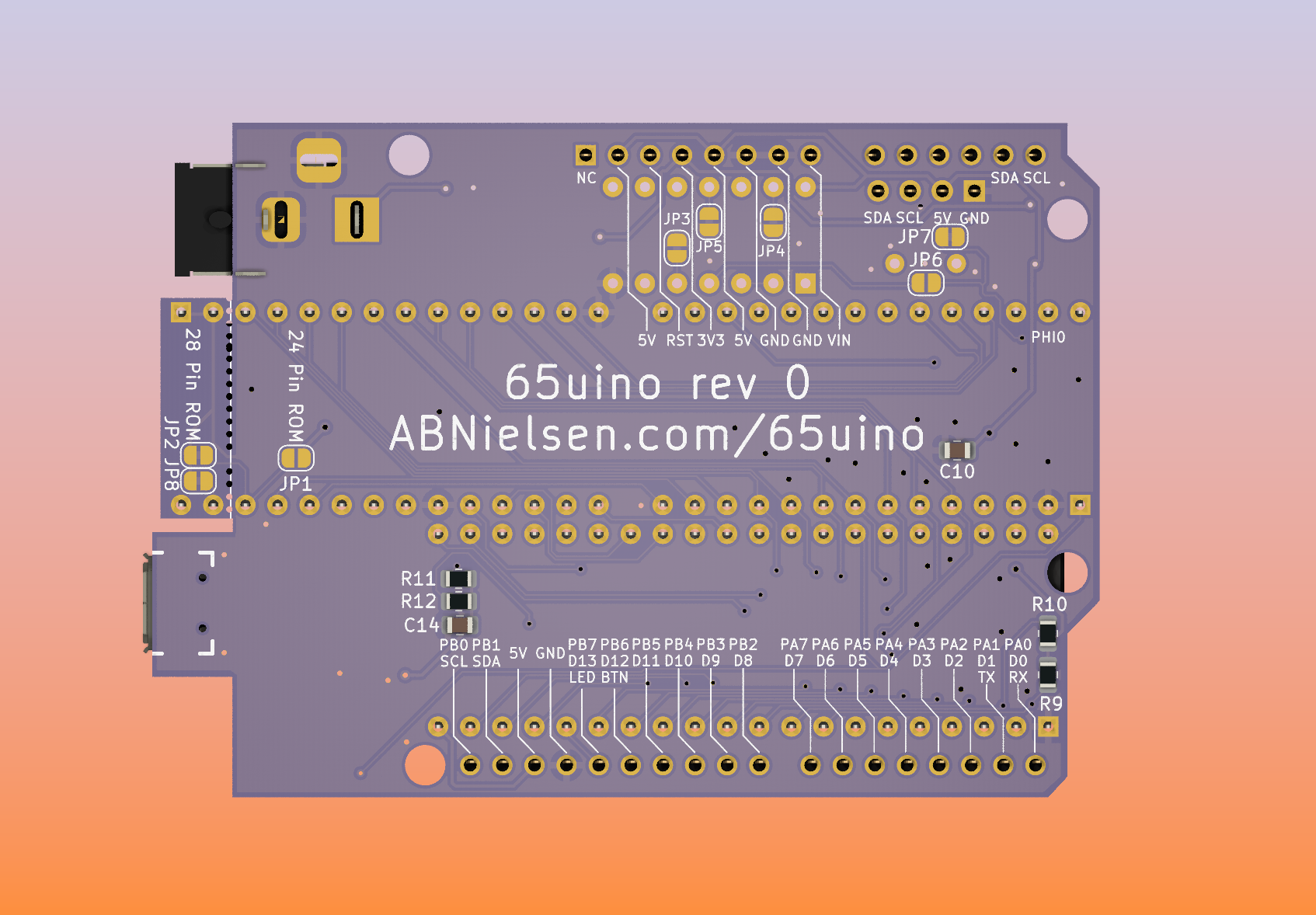
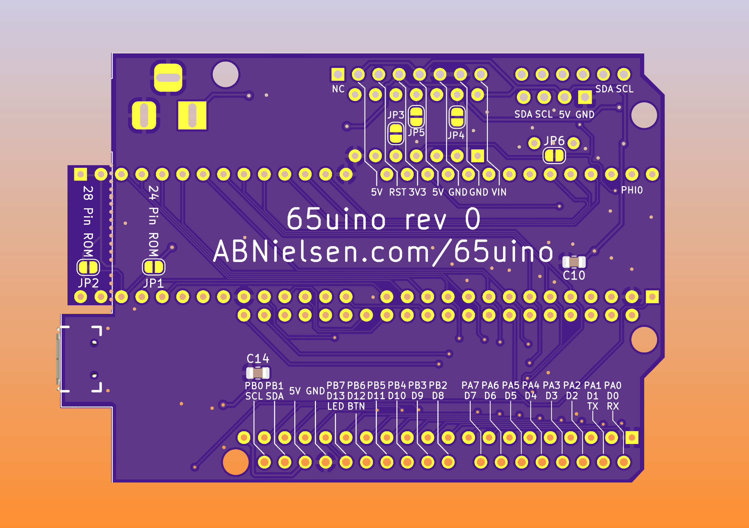
Speaking of: I updated the silkscreen so you don't need a computer nearby to figure out if you plugged anything in the wrong way - there is the slight confusion that D0-D7 on a 6502 usually refers to the data bus pins, but on an Arduino refers to the "[D]igital pins".
For good measure I also put the 6532 pin designations on the board - that should lessen the confusion.
Please note the silkscreen changes aren't in the gerber zip - so if you're sending it off to a manufacturer this week you might want to plot the gerbers yourself instead of the zip file.Oh! And I slimmed the board a bit to make sure it fits in the "official" 68.6mm width of an "Arduino" - excluding the USB and cuttoff section of course.
![]()
-
Of course it does I2C!
06/17/2023 at 12:50 • 0 commentsAs usual it took a bit longer than expected but I'm happy to announce I finally released my video on I2C on a 6502.. Or 6507 in the case of the 65uino.
I thought I could squeeze in the whole concept of i2c as well as making a somewhat complete SSD1306 OLED library in 6502 assembly into a single video, but that would've been way too long, so actually using the display with a small font will have to wait for next time. The video is already pretty compressed as it is.
I hope you'll enjoy it.