 Doug
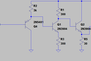
DougThe preliminary design is completed. A breadboard is done and the circuit has had an initial test.
Some notes about the project:
I wanted to utilize analog devices that I had on-hand, kind of a walk down memory lane of my electronics hobby and education. For the breadboard circuit, I found a 12V zener diode that was still in the Archer (Radioshack) package. I found metal can RCA op-amps that I had from a rummage sale of a retired Hewlett Packard employee. There is a wire-wound resistor that my brother and I had harvested from a TV set in the 1970's.
I only found one link to the pinout of the metal-can op-amps. It was a different brand, but the pinout turned out to be the same.
If I am comparing signals in the real-world, as long as the delays are the same, I can find which signal occurred first. The delay of the circuit is not relevant to the history of events.
 lukasz.iwaszkiewicz
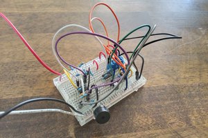
 Sergio Ghirardelli
 UTSOURCE