 kelvinA
[April 22, 16:45]
So @heinz (nozzleboss) recently added more information to a very promising method of obtaining a full spectrum of colours for FDM printers and I spent about an hour to get... this run.
Working with a subtractive colour space, white, cyan, yellow and magenta are the 4 colours needed to obtain all but the inkiest, dark hues. This is the reason that printers use CMYK; the white is the paper and the black is used partially because it's cheaper ink but mainly because it improves contrast. I'm personally fine with dark greys anyway, so I'm planning to get away with just using these 4.
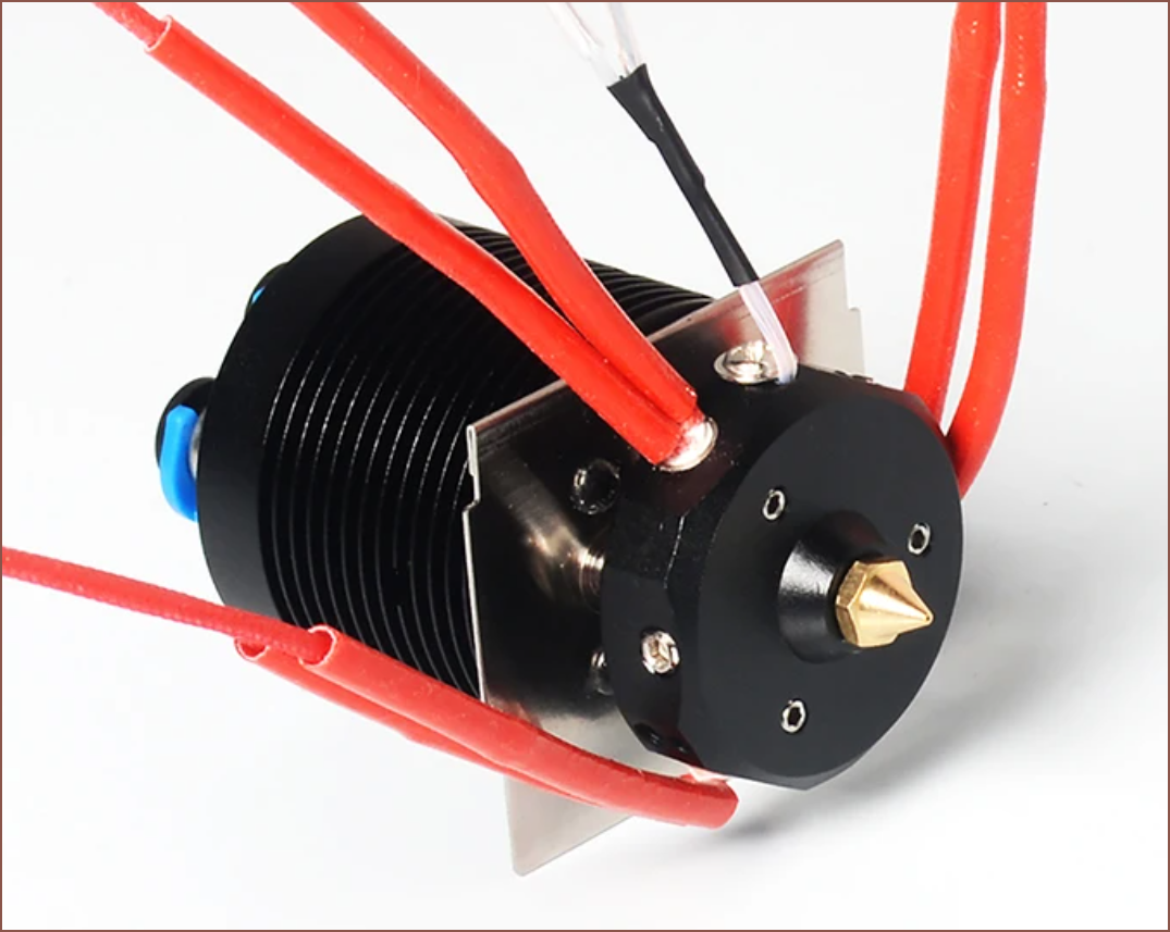
As you may (not) be aware, I designed a revolving hotend that rotated 3 volcano hotends so that I could finally achieve multi-colour, which is something I was planning on doing even before I owned a printer! (I got a diamond hotend in the mail before the CR-10 itself). I've also been keeping up with deckingman updates on his attempts of full-colour 3D printing. Now, I'm of a similar mindset to what was said by Zack Freedman, proposing that you think of a project as if someone else (in this case, You In The Past) came up and asked "can you finish this project off for me?", therefore I'm not exactly planning to just continue the project without first exploring the advancements that have happened in the 3 years since starting it.
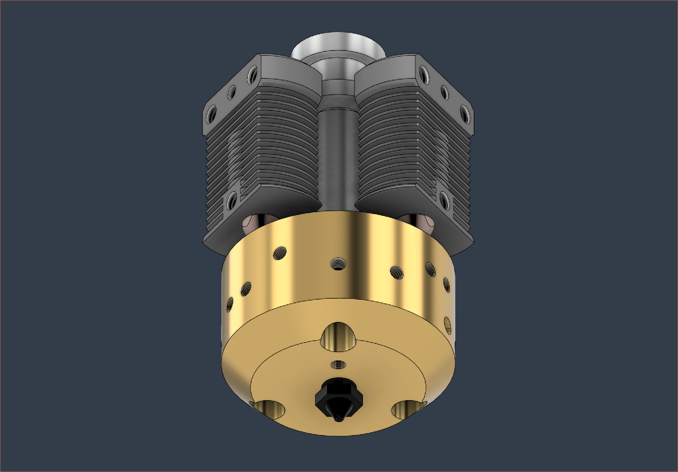
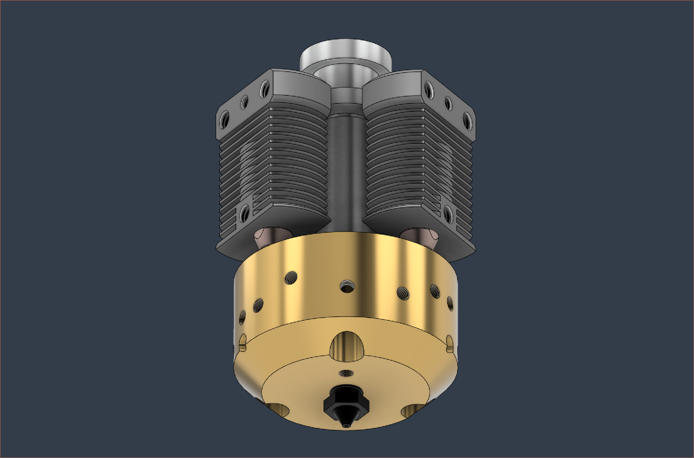
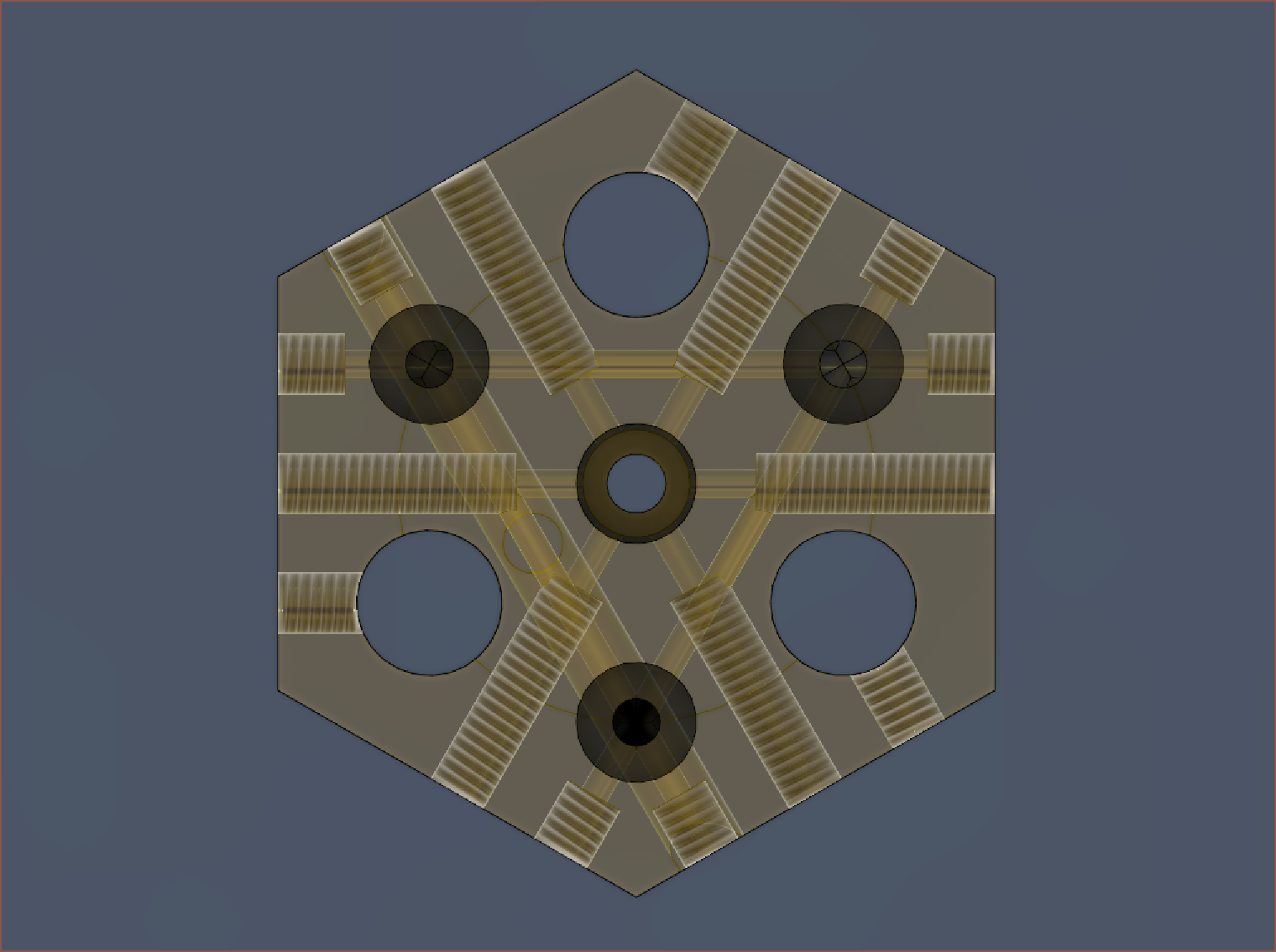
Now, coming in a heatblock footprint of 40mm diameter by 24mm deep, I've got this (hopefully) lathe-manufacturable brass solution. The heatsinks used are the small NF Smart (£15) in the centre and Lerdge(£1.50) ones around them. Along with the price, I'm also concerned about the NF Smart stock levels because it kinda looks like Mellow is just selling off their remaining levels.
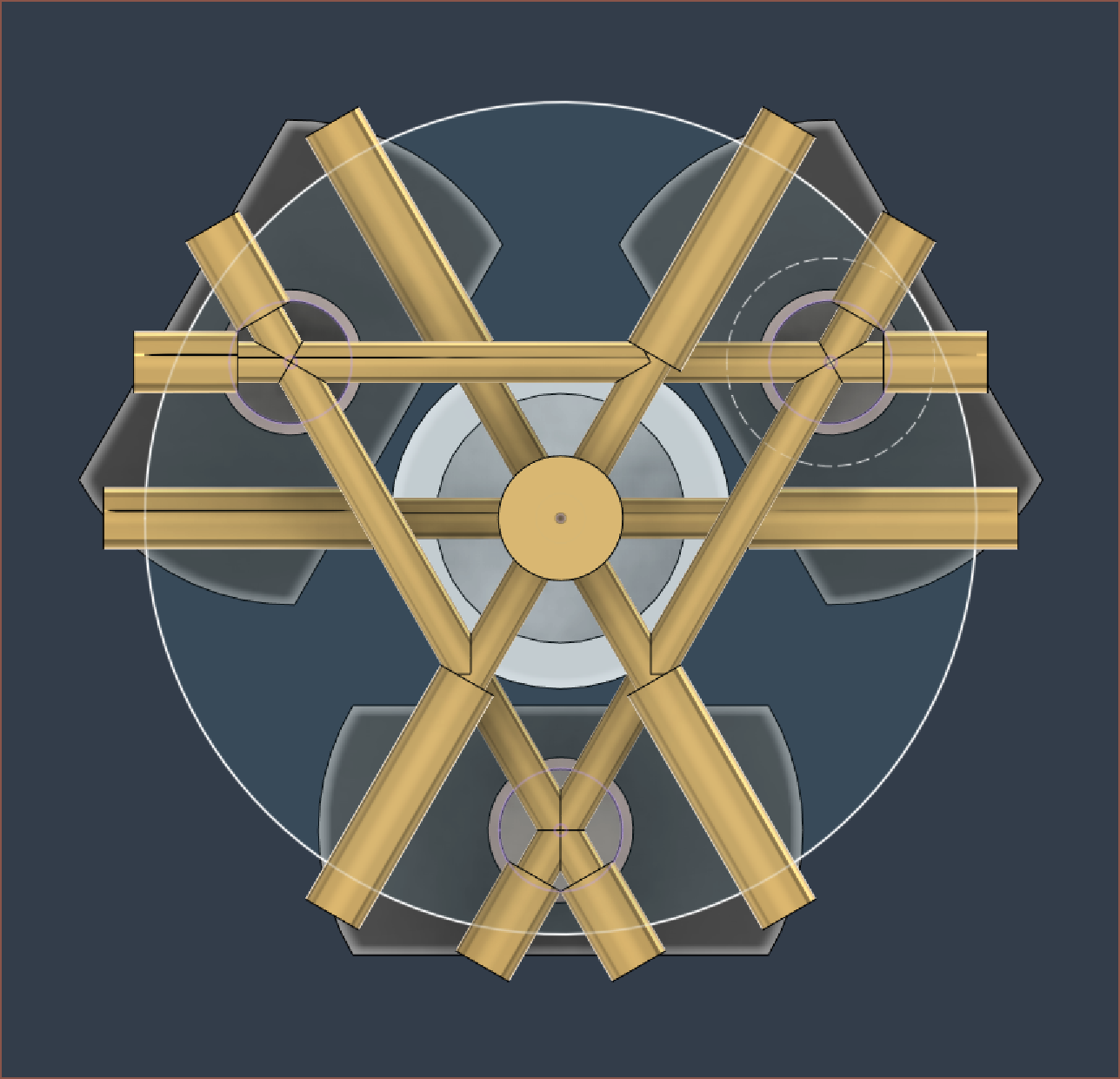
3mm grub screws are used to make sure that the material is going into the right direction. They're all at angles of 60 degrees apart so that many holes can be drilled from the same orientation. All the extra space are for things like thermistors and heater cartridges. The other reason why I wanted to design something like this was so that any potential clogs could be resolved by unscrewing the grub screws and poking a metal stick through the channels.
My biggest concern is the coating cuts. The idea is to use a tool similar to the one used to create threads. Thus, the main shaft is 2.5mm and the additional cut is only 1mm, so hopefully a sufficient tool can fit down the drilled hole and then start cutting.
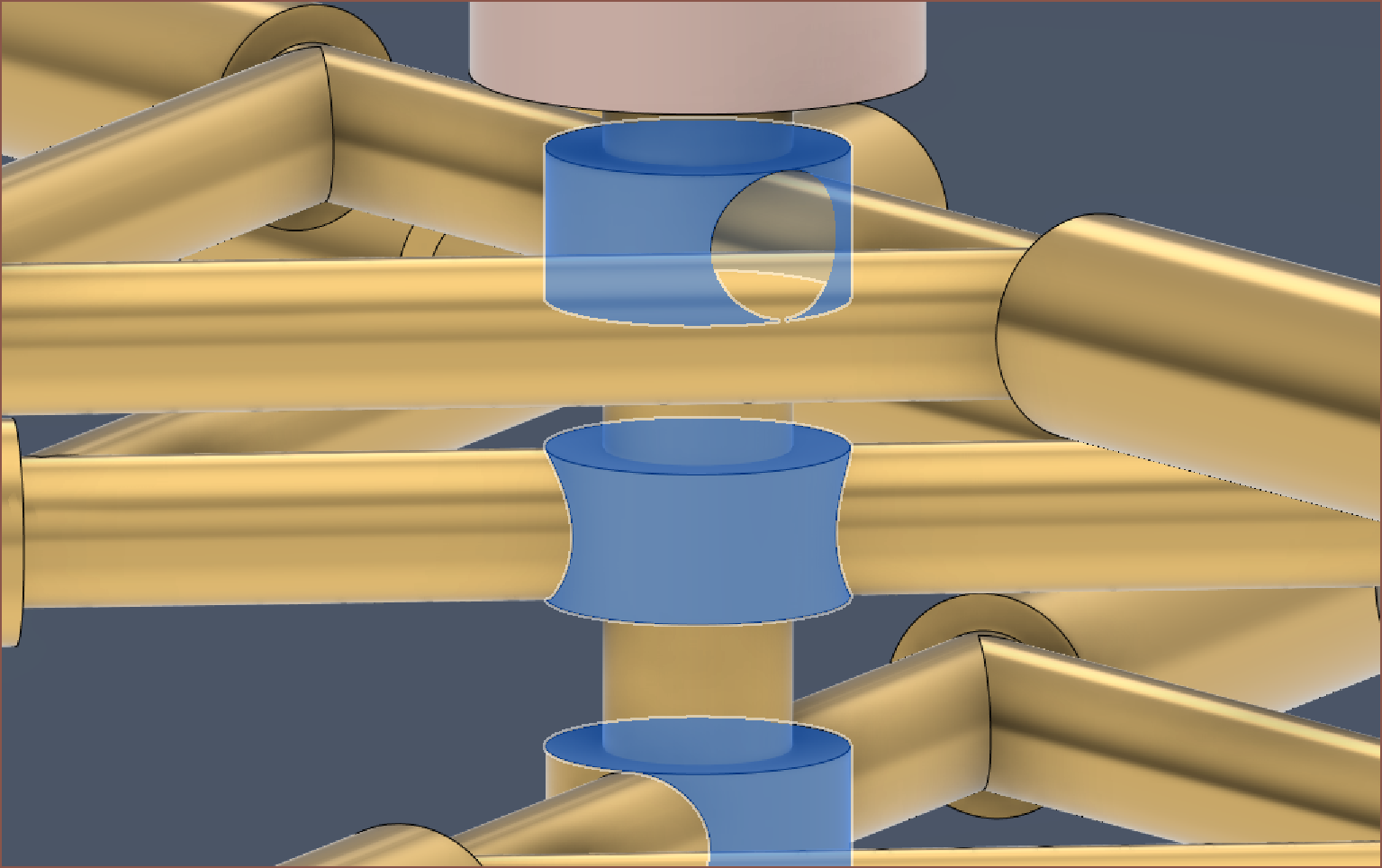
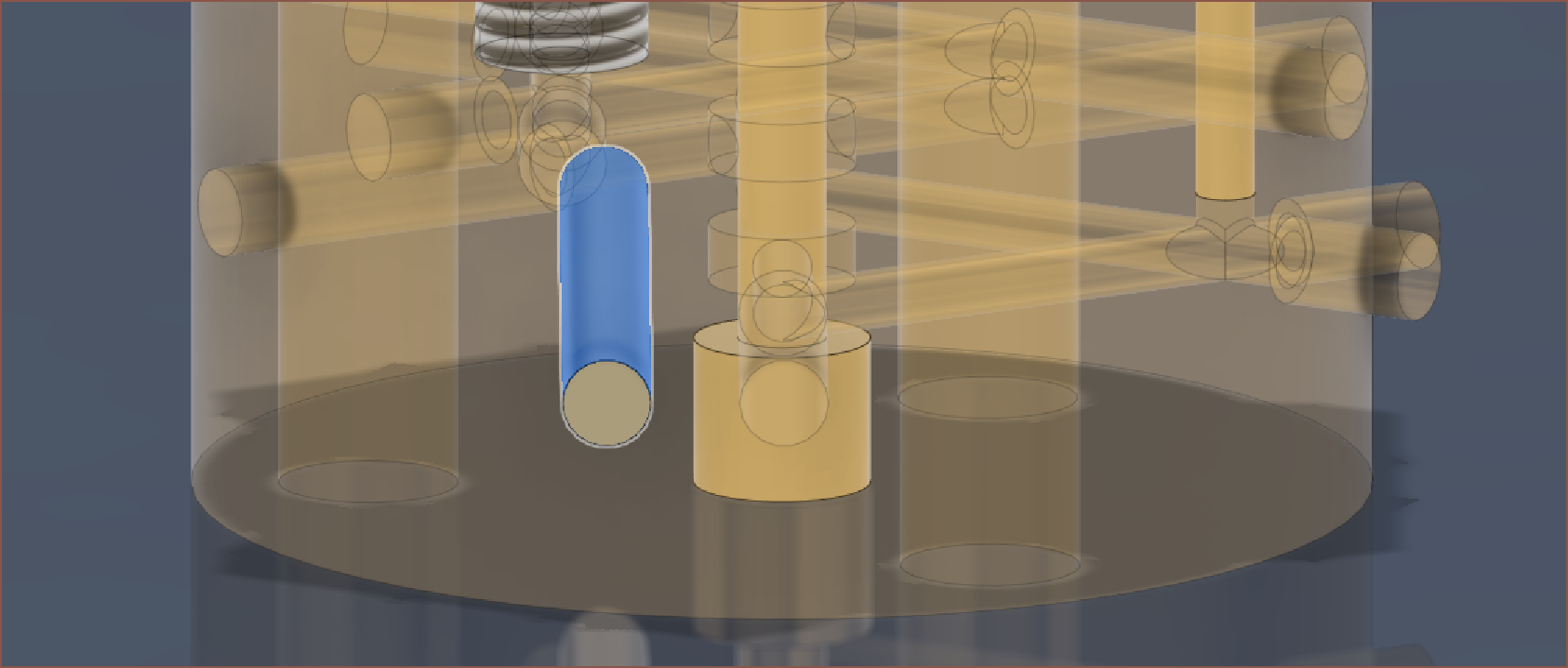
A 3mm main shaft is more likely to be manufacturable though, as well as reducing the unique amount of tools needed for fabricaition. Looking at the blender screenshot from heinz, I'd estimate that the voids are about 5mm anyway. However, I'm worried about the main 1.75mm filament curling in the shaft. I'll just try for 2.5.
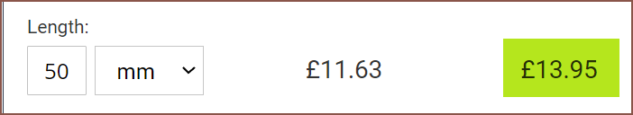
A D40*50mm round bar is about £14, so this heatblock is essentially £7 of material.
Similar to Geetech's solution, I'd imagine it's best to go with 3 20W cartridges:
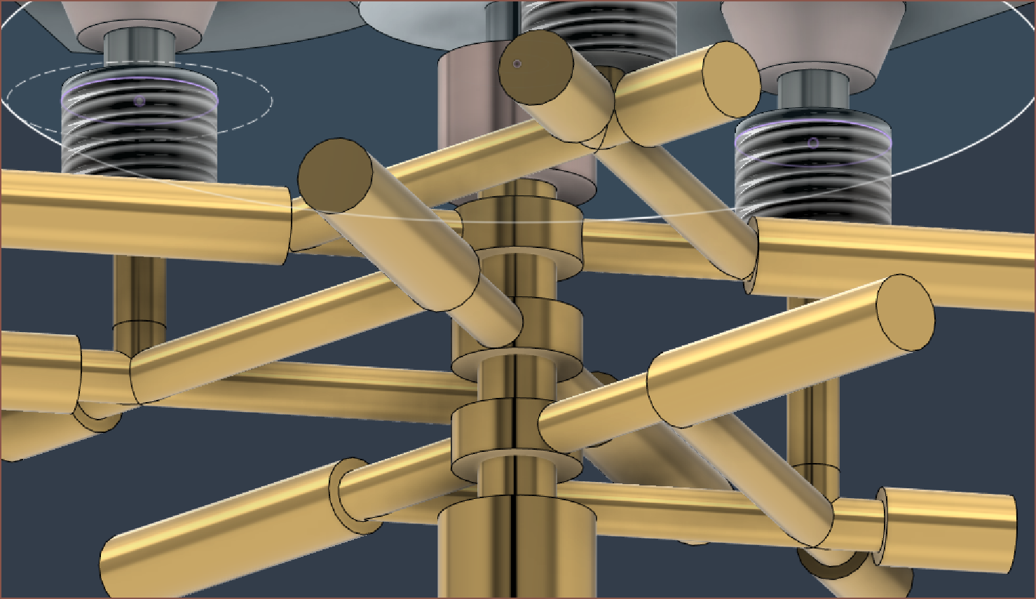
I'll assume the below location is as good as any to place the cartridge thermistor:
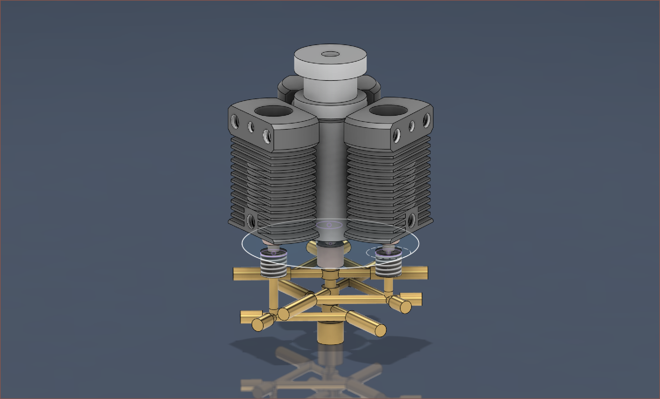
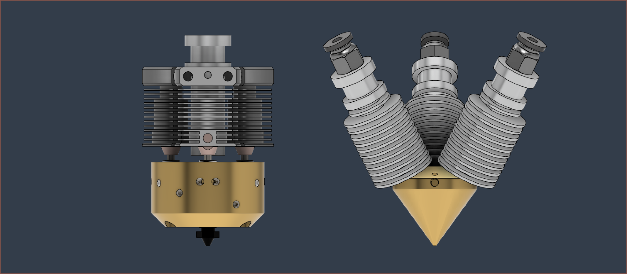
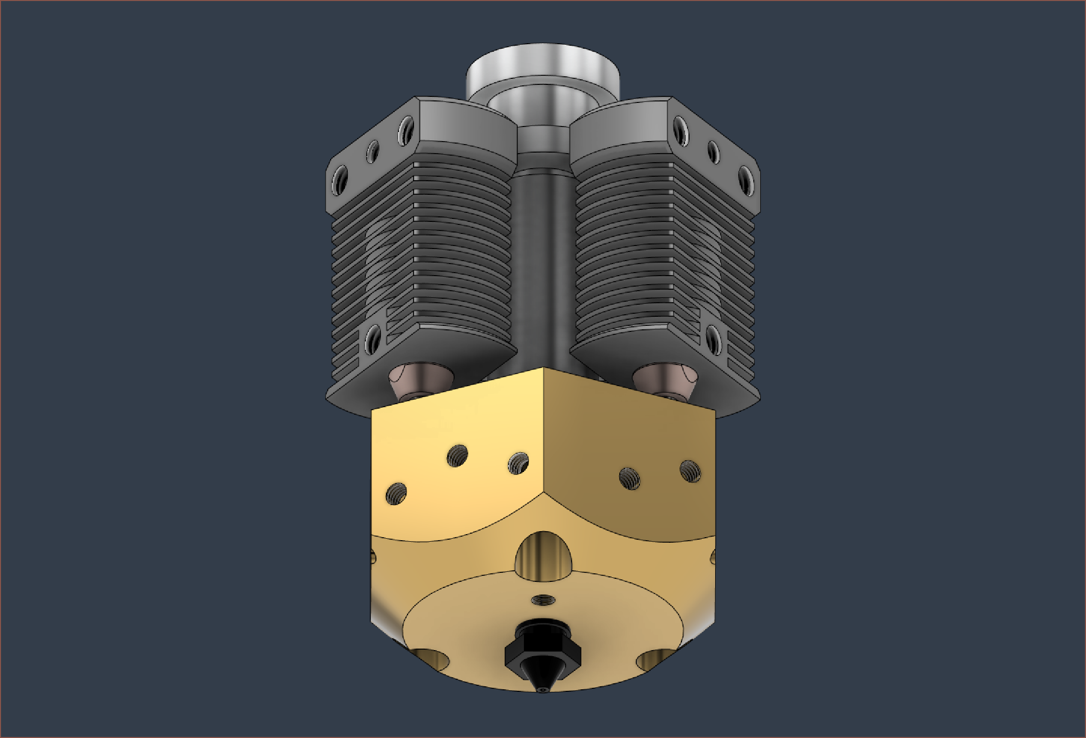
And there I have it, after about 2 hours of work:
This is what the hotend assembly looks like next to a diamond hotend model:
I'd imagine the both 3 x 20W (wired in parallel) or 1 - 3x 40-60W would work for this design, with the former having more even heating. Considering that the supervolcano is 2x a volcano in mass and has a 80W cartridge, I wouldn't be surprised if this block, which has 3x the mass, can use 120W of input thermal power.
I looked on the auto-quoter at PCBWay and it's $38 to CNC and $67 for 3D printing in aluminium, respectively. It's $46 to CNC in brass. I haven't created a technical drawing so I can't see the price when threads are added. I'd assume I'd follow the E3D technical drawings to see how to lay it out. Considering that Mellow uses brass for their supervolcano, as well as the diamond heatblock, I'm assuming that I might run into issues with a relatively large heatblock made out of aluminium.
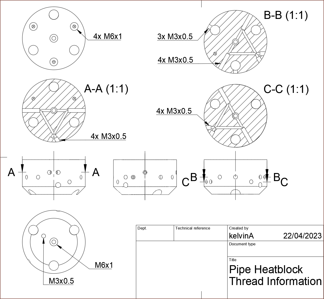
[19:45] I'm hoping that this drawing along with the .step file is enough to tell PCBway / university technicians what holes are threaded and what ones aren't:
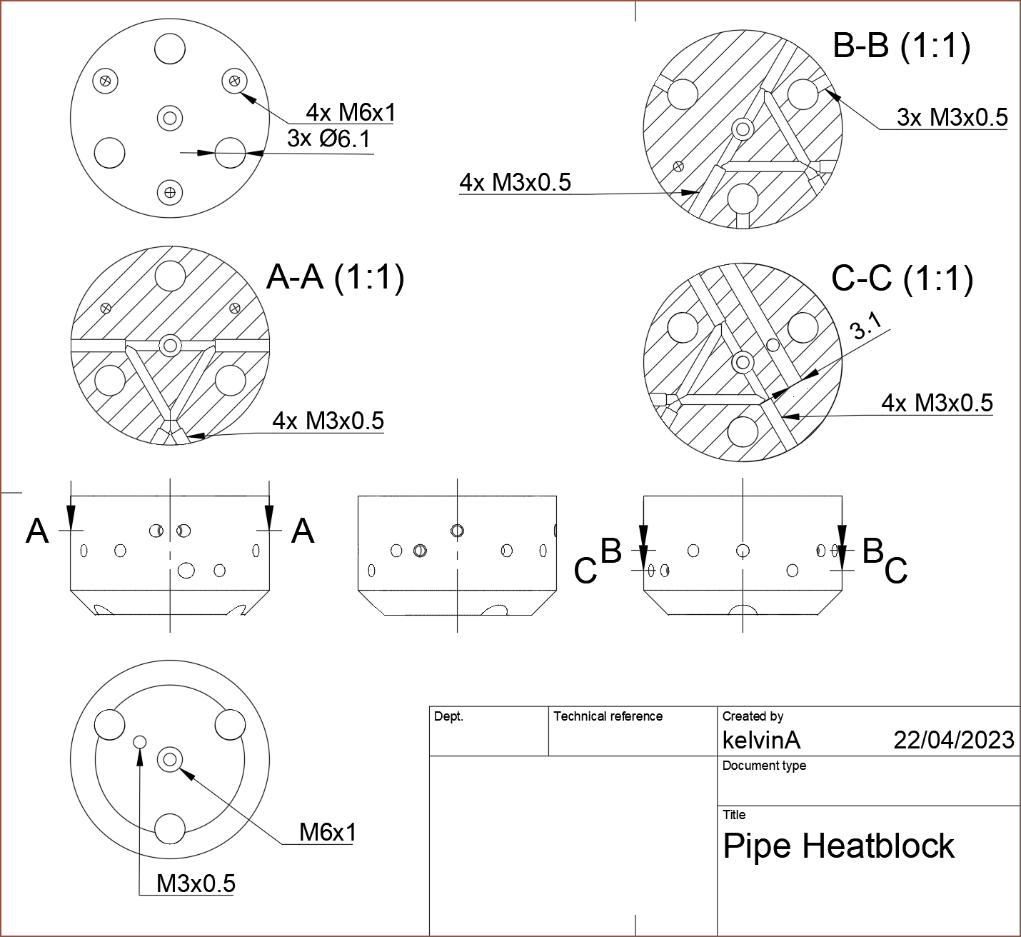
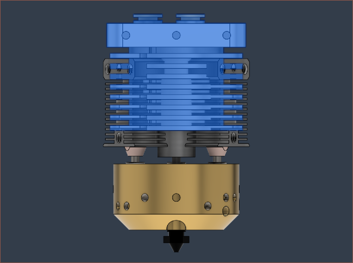
[21:30] I've seen the below video and made some tweaks, mainly reducing the diameter of the internal channels from 2mm to 1.5mm. This reduces the cross sectional area from 3.1 to 1.8mm^2, ideally increasing extruder-to-nozzle reaction times; 2 x 1.8mm is 3.6mm^2 which is 0.5mm^2 larger than the 2mm input channels and 1.2mm^2 larger than 1.75mm filament, thus there shouldn't be as much of a volume difference when the filament splits into 2 directions.
I've also reduced the thread from 6mm to 5.25mm for MK8 nozzle compatibility. The block is now 22mm thick. Here is the Pipe Hotend compared to the Revolving Hotend:
This is quite the complexity and size reduction, whilst increasing capability and reliability. This revolving hotend is the main thing stopping me from getting the CR600S back into commission so that I can print my various projects, and this new solution seems to be the better way forward.
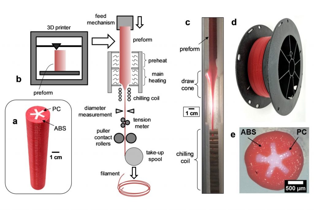
In addition to multi-colour, I can finally have 1-hand nozzle changes and I'm thinking it'll be possible to print expensive aesthetic materials with a cheaper internal filament, or even do this cool ABS outer shell + PC inner core for the material properties of PC with the colour options of ABS:
 [April 23, 12:50] The good news is that PCBway said that the block is machinable in brass.
The bad news is that it's $90, though it's slightly cheaper than the Revolving Hotend. I'll see what CNC and 3D printed aluminium costs. What I know so far is that this block in aluminium weighs 60g (a bit under 1/3 of brass).
I'll also see if 1.2mm channels are possible. 1.2mm nozzles have very good flow, so I can't imagine any issues with things like clogs in that aspect. 2 channels combined have a cross sectional area of 2.26mm, a tad lower than the 2.40mm CSA of 1.75mm filament. I might even be able to get some high-flow characteristics of the C-C filament path as it has geometry similar to the 3DSolex / CHT nozzles. My worry is that the channels are 23mm long and I'd imagine the smaller drill bits are more fragile, as well as requiring higher tolerances so that everything lines up. Will this prevent manufacturability or increase costs? I'll find out. The block height would be 21mm.
[14:25] Aluminium 6061 is $84 for both the 1.5 and 1.2mm channel variants.
Considering that it's (slightly) cheaper, lighter, higher conductivity and allegedly has a clamping force that could prevent leaks, it seems that the 1.2mm channel version in 6061 is currently the best choice... for lower temperature materials. Dyze seems to back up the notion that brass C360 is the better material, though this is from the perspective of high-temperature printing.
Thus, since there are 20 threaded sections in contact with molten material in an industry where leaks are enemy number 1, and a 200g hotend assembly is in the ballpark of direct-drive hotends anyway, I'll stick with brass.
[19:30] I've increased the internal ring cut from 0.75 to 1mm again. I just imagine that the smaller this internal cut, the more of a toothpaste effect I'd experience. Mass of the block is now 183g.
[24 April, 12:15]
Firstly, the above change is still manufacturable, according to PCBway. The hotend is also about the same size as 3DSway's seemingly now discontinued 3-in-1-out hotend (Mellow has it though), just perhaps 20mm taller:
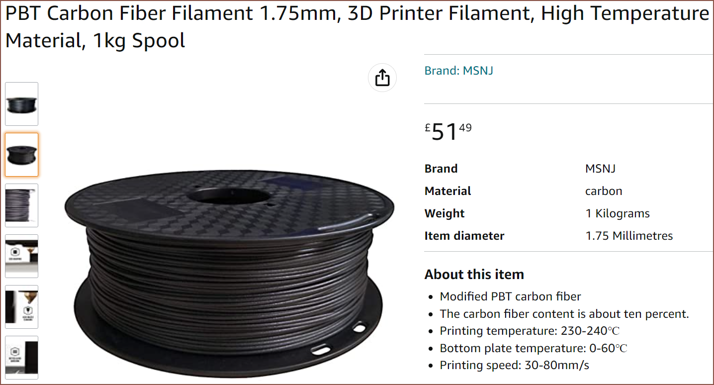
Secondly, I did some research on available materials, and removing all the ones that require special bed interfaces / strict water content management / hot enclosures left me with materials that essentially are all printable at 230C. That temperature might be a tad hot for PLA and PVA, a tad cool for PETG and (dare I print) ABS, probably fine for TPU and right in the zone for some carbon fibre PBT, which has higher-than-PLA stiffness, low water absorption and low warpage without an enclosure, despite having a working temp of >=130C (140 -1 50C usually claimed).
For reference, ABS is about 95C and PC 120C, looking at this video:
The raw pellets are also sub £5/kg, so if PBT sounds like obtainable unobtanium, I know. That's why I wanted to manufacture and almost exclusively print in it, as well as create my revolving hotend so that I could print in this temperature range (whilst still having multi-material capability). The cool thing with this hotend is that it would've allowed me to only make white PBT and then I can colour it on demand, instead of having wasted transition purges from colour to colour.
From this research, I can deduce that I'd actually be fine with a multimaterial hotend that shares the same temperature for all extruders.
Thirdly, I was thinking that this hotend could also be used to finally allow for continuous fiber composite printing:
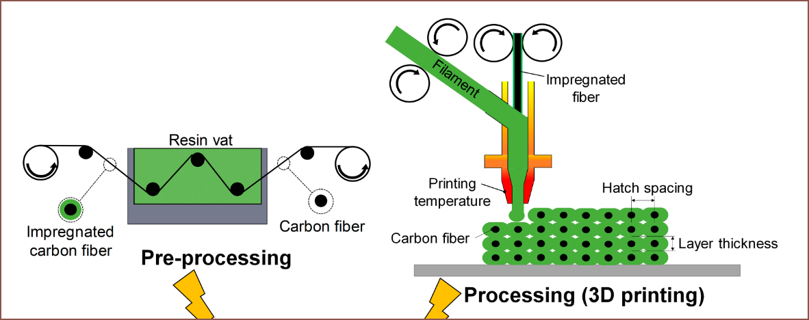
As you can see from the above image, it seems fairly straightforward. I'd imagine that the impregnation is partially because the continuous fiber is actually a bundle of really small strands that don't really have anything to keep them together, resulting in them all splitting and diverging when it hits the molten filament.
Even conductive prints by inlaying in a thin copper wire could be possible, likely with "conductive" PLA termination ends. So could pumping nothing but air in for light yet strong parts via AMTEx:
Considering that this hotend block design supports everything I want in a current-gen FDM printer, I've got to try it to see specifically why "reality is often disappointing". This is FDM 3D printing, and I'm only 48 hours into this project; I totally expect someone, years ago, to have attempted this exact same thing (though I don't know where on the internet (if it was ever documented on the internet) it is).
[16:20] PCBWay says that the aluminium 3D print is $122. JLCPCB will print it in stainless steel for £59 ($73.50), weighing 350g, though I'd expect that I'll have to manually tap holes. Dyze uses steel that is 3x more thermally conductive than stainless 316, so I'm not sure how well it will work. Hopefully, 3 heaters allows for uniform heating.
I've also fully dimensioned the drawings and will see if that changes the CNC price (maybe the engineer missed the 1mm internal grooves or something).
My uni also doesn't happen to have the internal grooving tool for fabrication (or drill bits <=2mm by the sounds of it), and in my quick online search, it looks like a 0.7mm max depth internal groove tools usually needs a 3mm minimum bore size.
[25 April, 02:00]
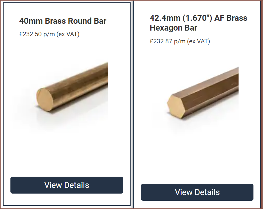
It turns out that 42mm hex bar is the same price as 40mm round bar:
I assumed this was talking about diameter and so I modelled it up in 10 minutes, and it was 171g in mass. I'm assuming that it'll be easier to start the initial hole and/or tap threads with a flat surface. Additionally, the 3 grub screws that hold the heater cartridges are on the same face, further reducing the amount of times the part has to be rotated to machine.
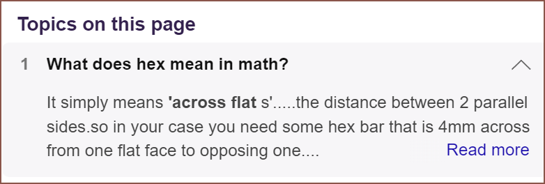
However, it seems that these are actually dimensioned from flat to flat:
For some reason, it seems that all the imperial dimensioned bars are noticably cheaper than metric ones:
36mm would be 165g and 38mm is 182g.
In other news, the round version is now magically $4 more ($94.08), now that I've included a full drawing. Oh, it could also be because I specified 3.2um surface roughness instead of 6.4um, mainly because Fractory starts at 3.2um. Not really sure if it'll make a difference as long as the roughness is manageable for surfaces the material contacts, but I don't want to chance a £75 part just to save £3.
[02:40] Oh, PCBWay just checked it over (still using the old tech drawing) and it's $93.85 for the hexagon variant with 3.2um surface roughness. I can't see much reason not to go with the hexagon design going forward.
[20:00] On the topic of inlaying copper into the print, I had some more time to think about it.
From my experience trying to make PCBs as of late, as well as looking at CNC PCB fabrication years ago, it seems that the aim for productive use is to have a 0.2mm trace/space width, and ideally 0.16mm. The nice thing about that is that it would be achievable to have the same trace-to-trace spacing with a 0.4mm nozzle (or 0.3mm for 0.16mm).
This could be a potential solution, though I worry if the tinning will survive 230C. As long as it's uncoated or coated with something conductive, it's good to go. This wire is equivalent to 32AWG. Now, according to this large table, the conservative current carrying capacity is 500mA which I find kind of odd because every PCB trace calculator says that a 0.2mm wide, 35um thick trace can easily carry over 1A with a temperature rise of 40C. 32AWG is 31,459 um^2, and that trace is 7,000.
Ideally, the copper wire will scrape on the edge of the nozzle orifice, resulting in the wire being right at the top of the path and allowing for straightforward contacts, however I assume that there will be plastic covering the end terminations. For the short distances between the copper wire and surface, conductive filament may have a low enough resistance to be usable. However, it seems that the contact resistance of conductive filament may become an issue:
Conductive ABS looks to be the better solution. Its higher working temperature than PLA could be a reason:
[April 26, 03:00]
First, I took 30 minutes to decide that I'm indeed going to go with a 38mm across-flat hexagonal prism instead of 36mm. The concern is with the cartridge threads, which were only 2mm on the 36mm variant. For 38mm, the threads are 3mm, which is longer than an M3 brass bolt (2.5mm). This part is kind of expensive, so I don't want to risk breaking threads.
Then, I updated the drawing with the new design, deleted all the previous attempts and looked to see what the actual standard surface roughness (6.4um) looks like, which seems fine:
Thus, I sent off the part for review...
Sixty seven dollars (£54). All my quotes until now have only moved the price point by the realm of pennies. Now I've saved almost 30% from the last one. I think the build time has also shrunk from 11-13 to 9-11 days, so it seems that being able to start drill holes on a flat surface really does translate into easier manufacturing. Now it's even cheaper than JLCPCB printing it in stainless steel, which along with the 2x higher mass and relatively poor thermal conductivity, would likely have a much worse surface finish and no tapped holes.
This is what the shipping rates to UK for a 190g item looks like:
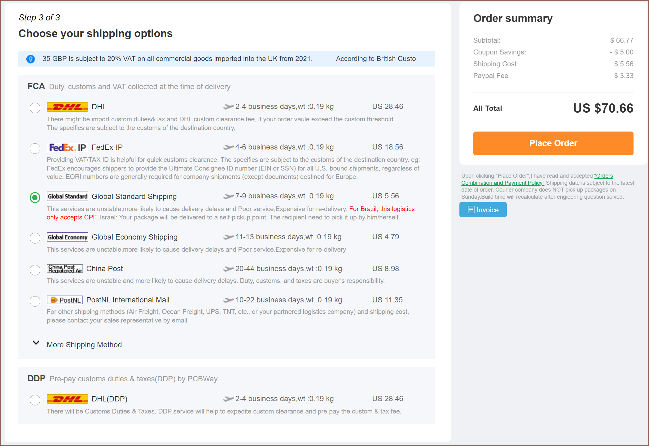
According to a PayPal currency converter, I'd expect to pay £55.50 right here and now, which is a "sigh of relief" amount. I should also expect that Royal Mail will ask for an additional £12 in duty charges.
[17:30] I've removed all the imported components from the Fusion360 file, fixed up and cleaned up the drawing file, skimmed around to see what the latest in multicolour/multimaterial printing is and finally sent off the finalized files for PCBWay review.
After 45 accumulated saves on a project that started over 96 hours ago, I think I can call this part of the project "I don't need to research/tweak any more" done.
[April 27, 16:30]
So, considering that I couldn't find a heatsink smaller than the 12mm LERDGE / Ender3 style hotends that still had a built in bowden coupler and mounting options (so those small Dragon-style heatsinks don't count), I went ahead with the $71 order.
If you were wondering (because I was), a 30mm across-flat block would be on the right edge of being geometrically sound, only weighs 99g aaaand... the autoquoter gave $42, so I'd assume that the engineer would do $42 * 1.5 = $63 since my part was autoquoted for $44 and the engineer changed it to $66.
You'd most likely need a custom heatsink for this. Perhaps it'll be possible to take a large, off-the-shelf heatsink that was designed for 1 filament, and drill holes for the other 3? Anyway, this is "university scientific research" as far as PCBWay and I are concerned, not about optimizing mass production (though it's nice to read about what it'll be like).
If you were also wondering (because I was), nozzleboss' printed heatblock cost $37 for a 28 x 25mm part in aluminium, though he self-tapped the holes.
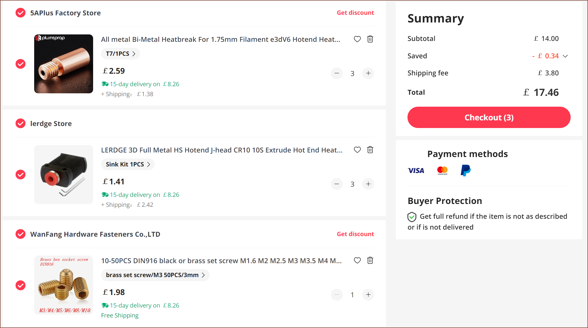
I've already got the £15 NF-Smart heatsink along with heater cartridges / thermistor / nozzles, so the remaining things I need to buy are the brass grub screws (so that I don't have to worry about thermal expansion coefficients), the bi-metal heatbreaks (making sure to get one with copper threads, again to do with that thermal expansion but also to have consistency with the NF-Smart, which has copper threads too) and the LERDGE heatsinks.
Considering the mass is 3x the mass of the (similar density) copper volcano heatblocks I bought along with the NF-Smart heatsinks, I'm just going to use 3 x 40W cartridges wired up in parallel to the bed heater terminals on the BTT OCT PRO I bought a while back (I wanted to use it for the SecSavr Sublime) that has enough stepper motor drivers for the job (and one spare, if WCMYK or WCMY+Support ever exists).
Speaking of the Sublime, I talked about Tube Printing in a log, and the fundamental geometry looks identical to if I were to take a nozzle for 3mm filament, drill a 2 - 2.5mm hole into it and then use something like a 2 x 1.5mm or 1.5 x 1mm brass tube that goes through the hotend. A similar solution would be used for things like 0.2mm copper wire and/or continuous fiber thread, and I wouldn't be surprised if I need to pump air though the metal tube just so that there is pressure to fight against the molten filament trying to go up the wrong way. I couldn't think of a good way to integrate this other than designing the hotend such that the 3 outer heatsinks hold up the hotend, and the middle one can be easily unscrewed so that an air / tube version could be installed. I'd need a different extrusion system anyway, so it seemed like a sensible solution as long as the change can be done in a couple of minutes without the risk of leaks.
Discussions
Become a Hackaday.io Member
Create an account to leave a comment. Already have an account? Log In.
I knew I had some bimetal heatbreaks, and I just found 5 of them. That saves me £14 on this project.
Are you sure? yes | no