 kelvinA
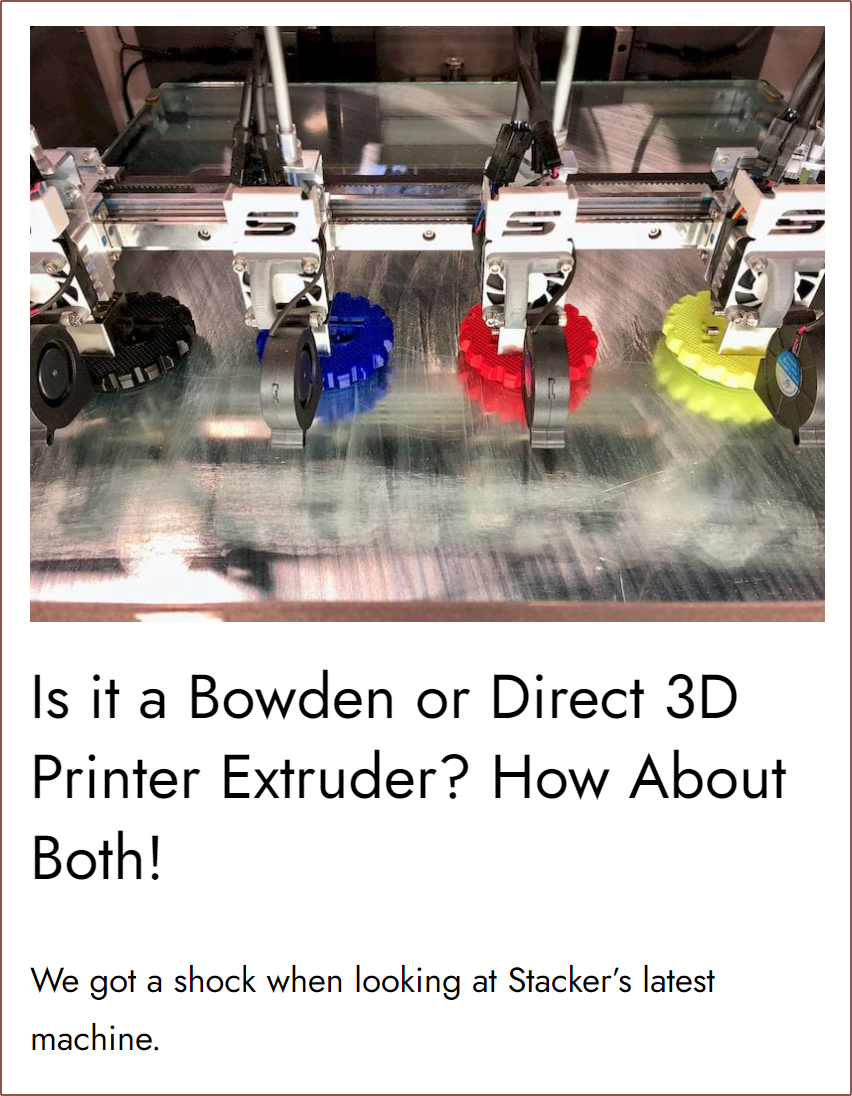
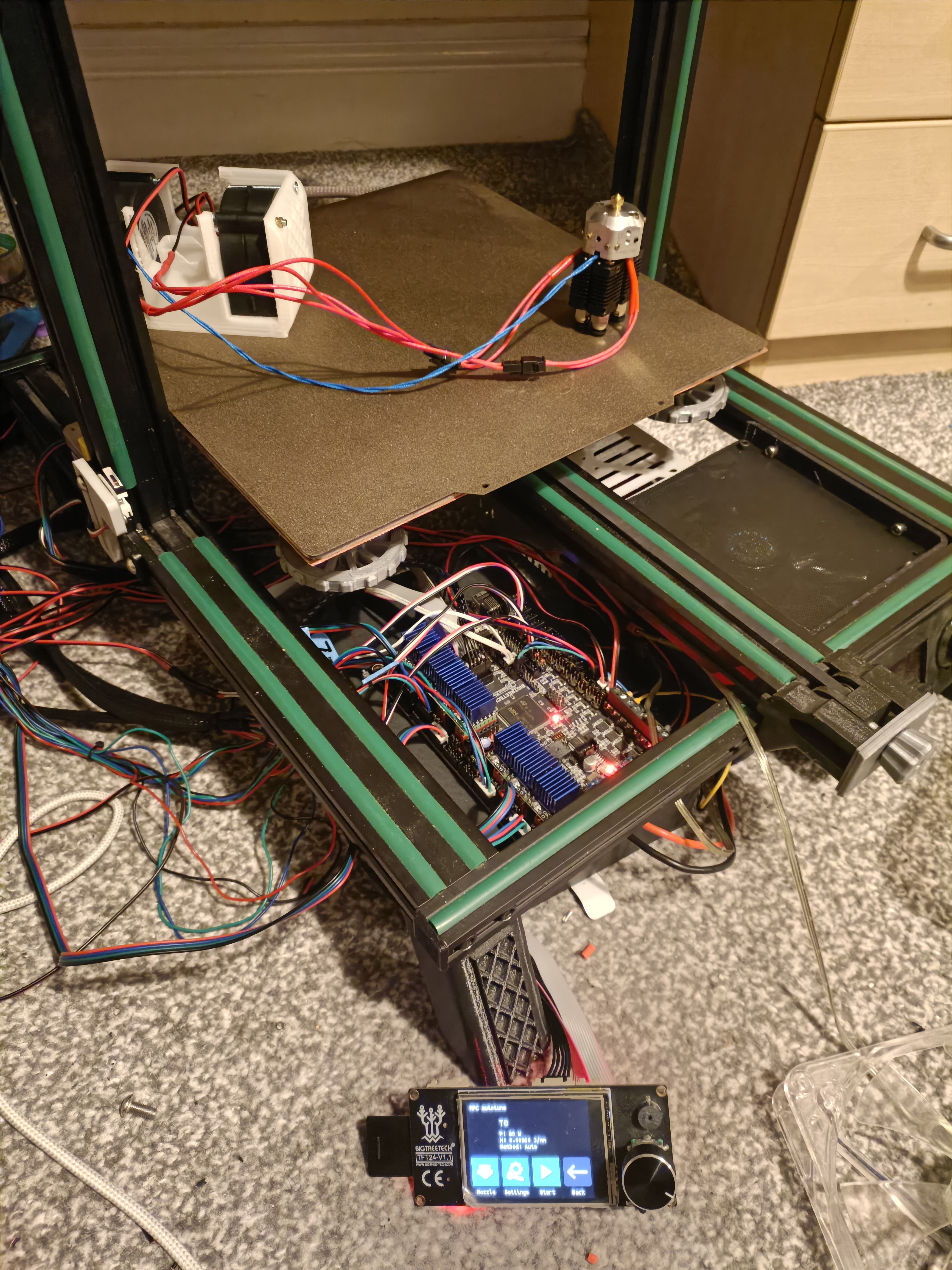
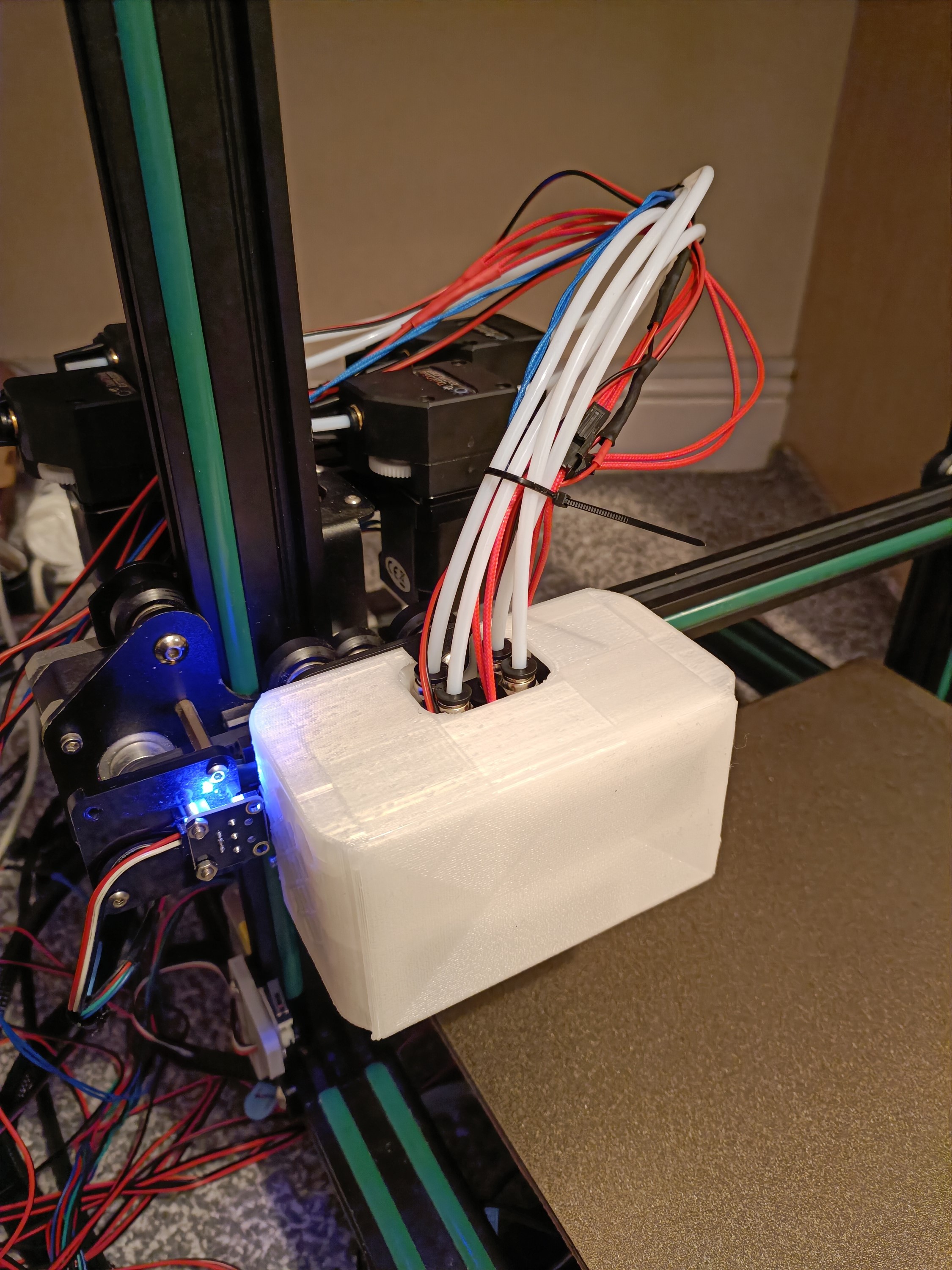
It took much longer than I expected, but I've finally turned the pile of parts into a CR600S to conduct printing tests with the 4-in-1-out Machined Coaxial Hotend. Unfortunately, it lost against the leaks and the results I was able to get out of the two test prints were inconclusive other than knowing that I can print 100% in extruder E0 and E1.
Putting the printer together
I started putting the CR600S together on the 23rd Jan, found out what parts needed to be ordered on the 24th and got them in on the 25th and 26th.
Extruder mounting
I had some Nema17 mounts from when I was testing for the #SecSavr Sublime [gd0036] and I figured out how to be able to mount them to the CR600Ss extruder mount plate:
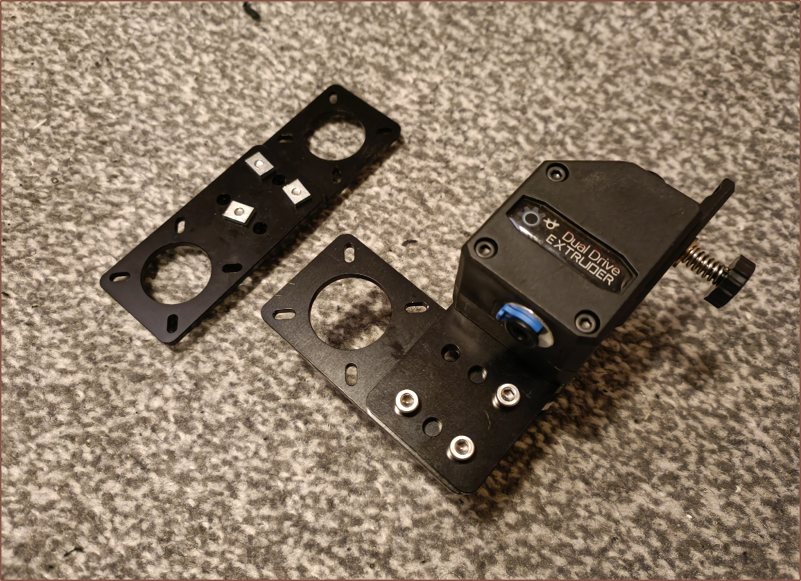
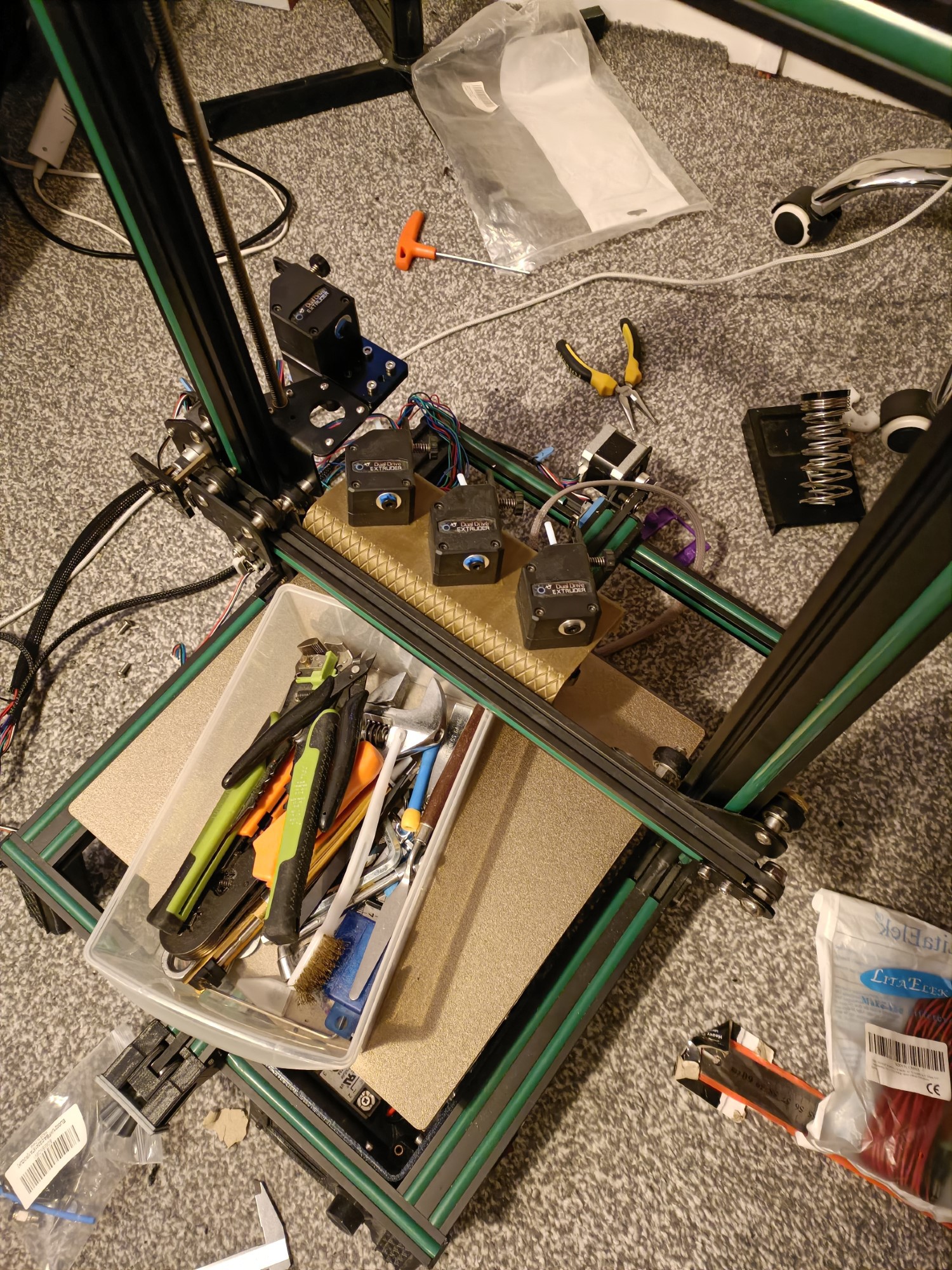
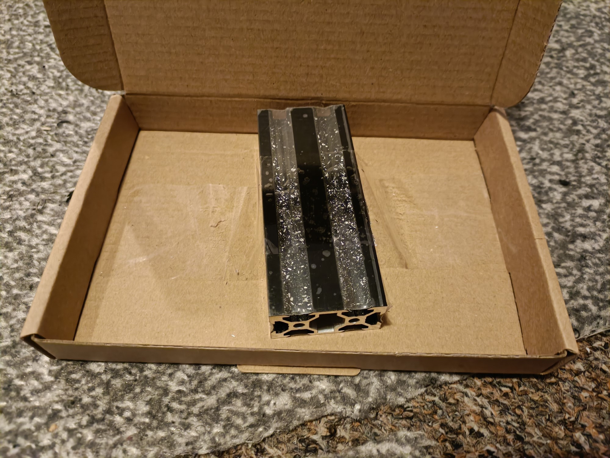
I figured out that it would be possible to get a 10cm length of 2040 extrusion to actually use all 5 mounts I have to mount the 4 extruders.
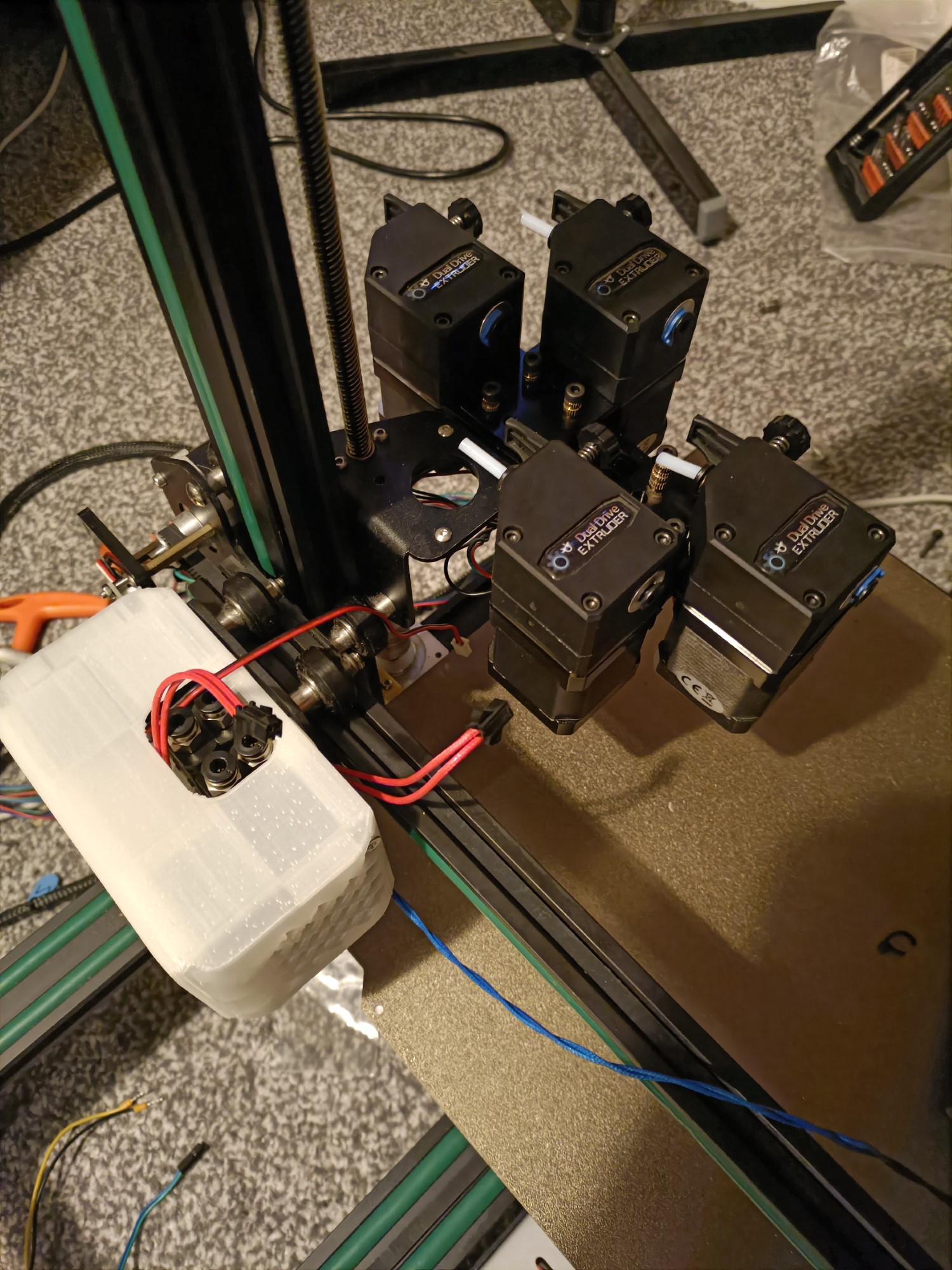
E2 gave me the most issue because, as I was installing it, I noticed that the grub was loose. It also wasn't tightening correctly. I put in a grub from the bag of them, but then I noticed that some motors could be spun from the white gear things and others can't. For all but E2, the issue was that the gear was too high up. However, it took me trying the E2 extruder on E3 to realise that the (longer) grub screw is the reason E2 wasn't working. I had to transplant a screw from one of the BMG gears I got for the #SecSavr Select [gd0091].
Some other parts ordered
It wasn't until I was wiring things on the 29th that I realised that I hadn't actually seen my box of ferrules in years, so I got 600pcs of those.
Parts redesigned in CAD
The only thing I modified so far was the screen foot:
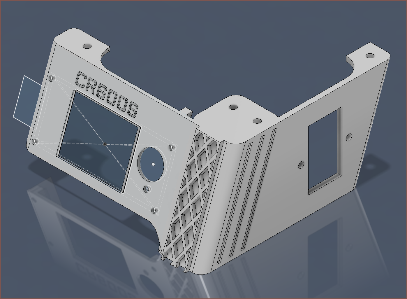
The dimensions of the BTT TFT24 were very similar to the FysetC RGB 12864 installed currently. The plan was to use this as a test print.
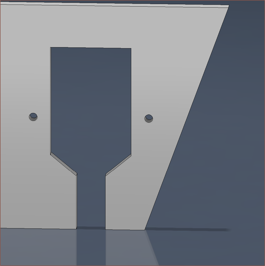
I added a cutout so that the mains wires didn't have to be disconnected when swapping this part out if needed in the future.
More mechanical ideas
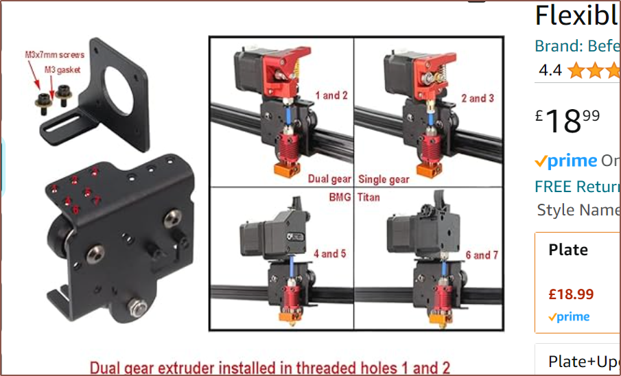
Possibility of a micro-bowden (direct drive) fed input?
This is what gave me the idea:
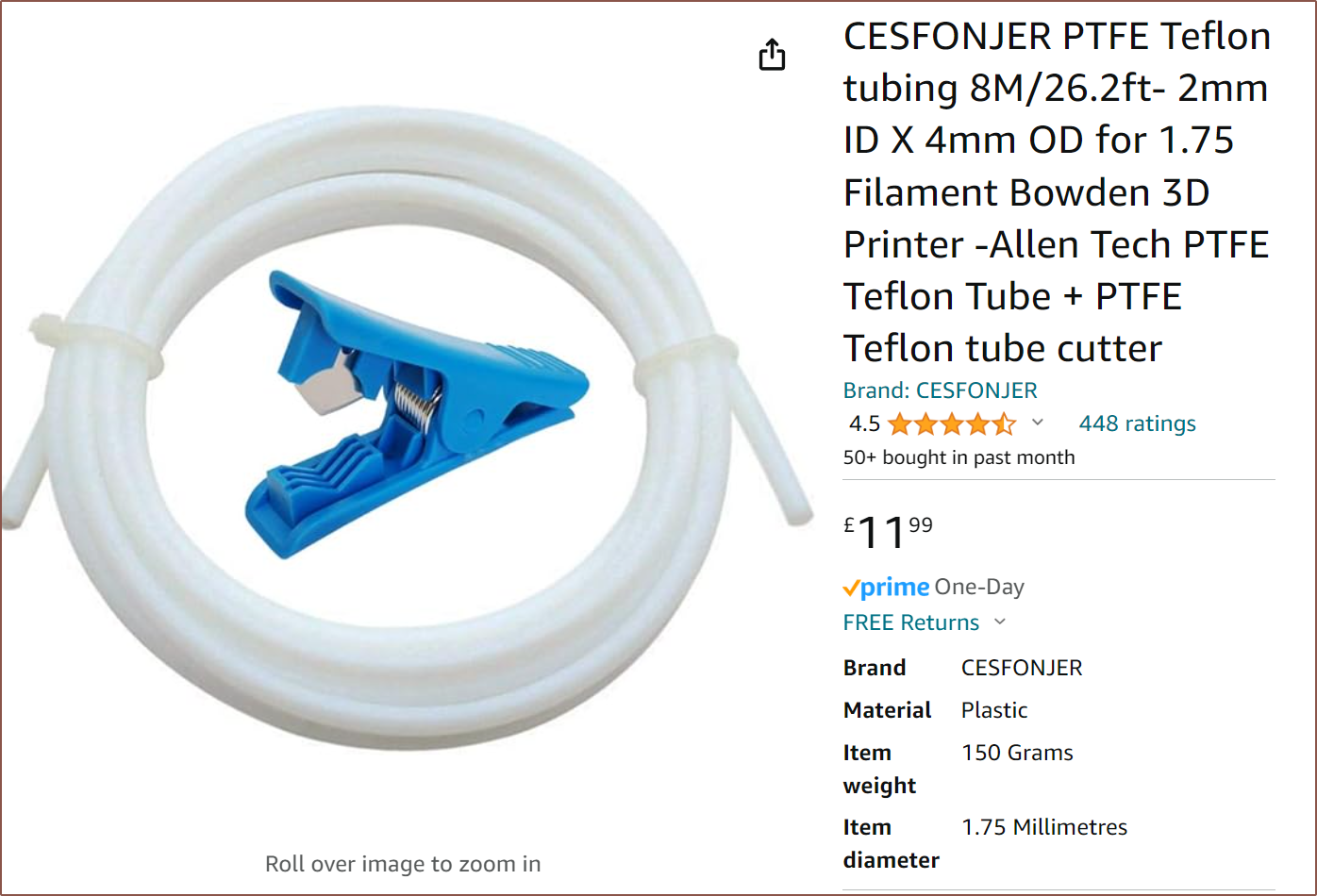
And this is what I plan to use:
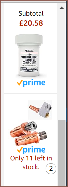
BotObjects heatsinks?
Whilst on my Fabbaloo travels, I came across this:
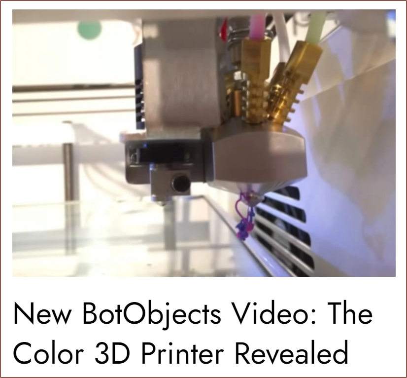
As you'd see later in this log, I think something like those brass inserts is something that is really needed if either the Machined, Printed or Unibody Coaxial Hotend is going to work long-term.
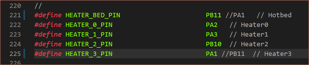
Firmware changes

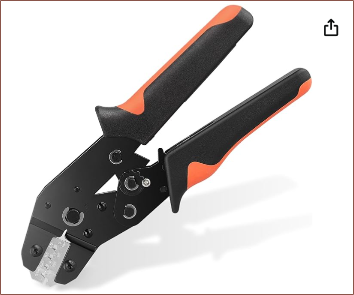
JST XH crimping using the SN-2549
- Change to the lowest pressure setting
- Remove a bolts
worth of insulation on the wire
- (there's a bolt head that spans from the cutting edge of the stripper, so that's why I say that)
- If in doubt, strip shorter. There really only needs to be 3ish millimetres of exposed wire.
- Use a 2 pin JST-XH female to
hold the crimp mounted
vertically.
- If horizontally, the unused pin will hit the crimping jaws
- This also protects the small tab on the underside from getting crushed.
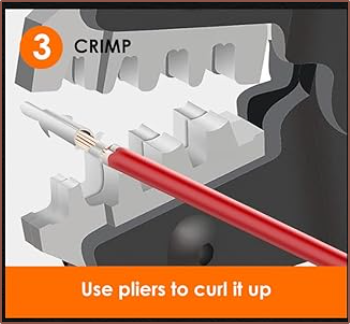
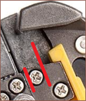
- Place crimp into 0.08 option
- Crimp down till the jaw holds the male crimp
- Place wire in and validate that the insulation barely passes the large tabs (the ones that are supposed to crimp onto the insulation)
- Crimp fully and use the 2pin JST to pull it out.
Trying PTFE tape
- Tried folding a strip in half and wrapping it around
- Too thick
- Tried cutting a smaller length and then cutting it in half to get 2 narrow lengths of tape
- Then I used an M6 bolt to testfit and it seemed that most of the tape got pushed up
- Tried to install into the hotend but I couldn't get it to go all the way down
- Spent 5 minutes taking it all off and just seeing how far I get with all 4 breaks tightened at 150C.
X axis endstop
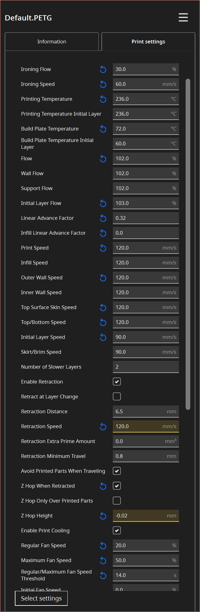
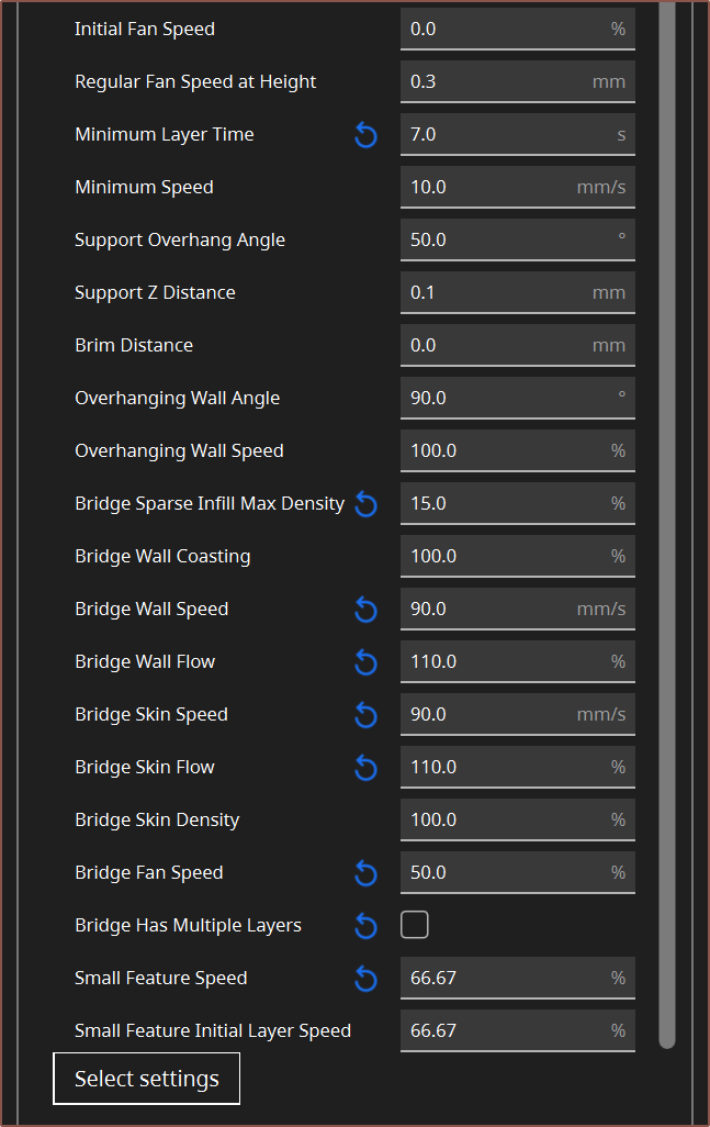
Slicing

First print attempt
Expected ratios for vtools (starting at T0 = 1.):
- 1/0/0/0
- 0/1/0/0
- 0/0/1/0
- 0/0/0/1
- 0.5/0.5/0/0
- 0.75/0.25/0/0
- 0.9/0.1/0/0
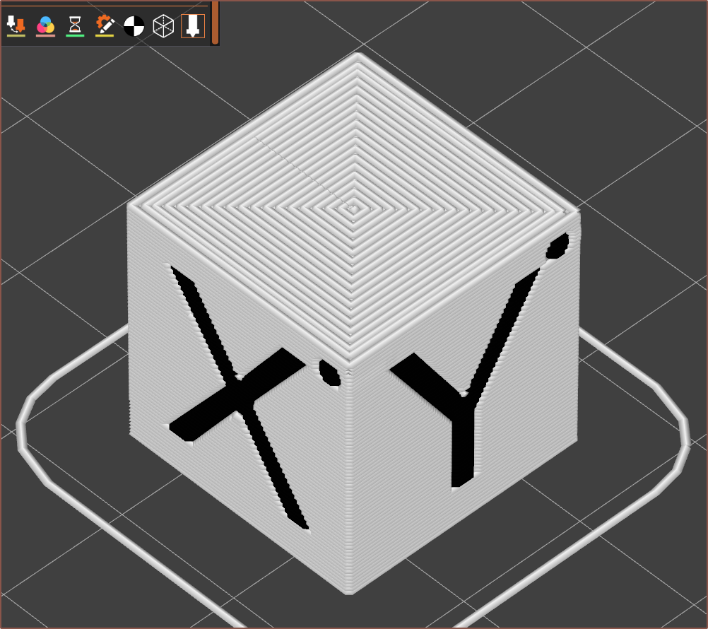
This is the first result:
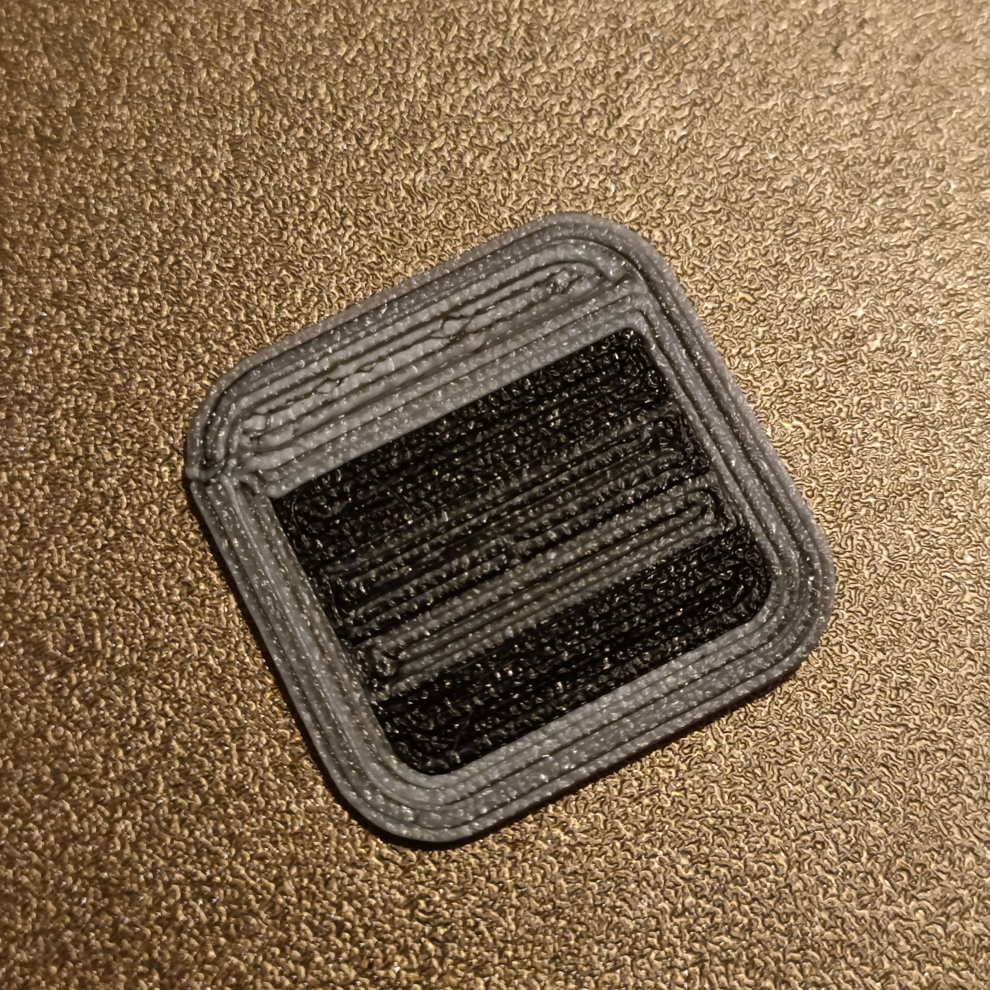
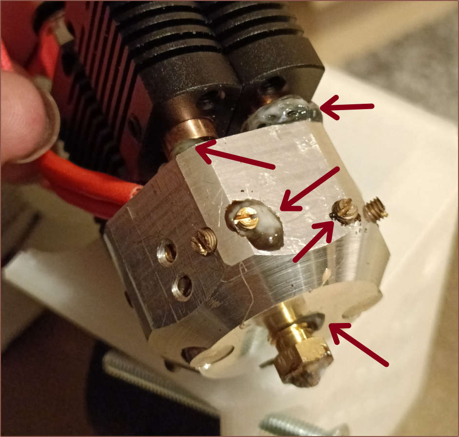
This is the hotend after the print:
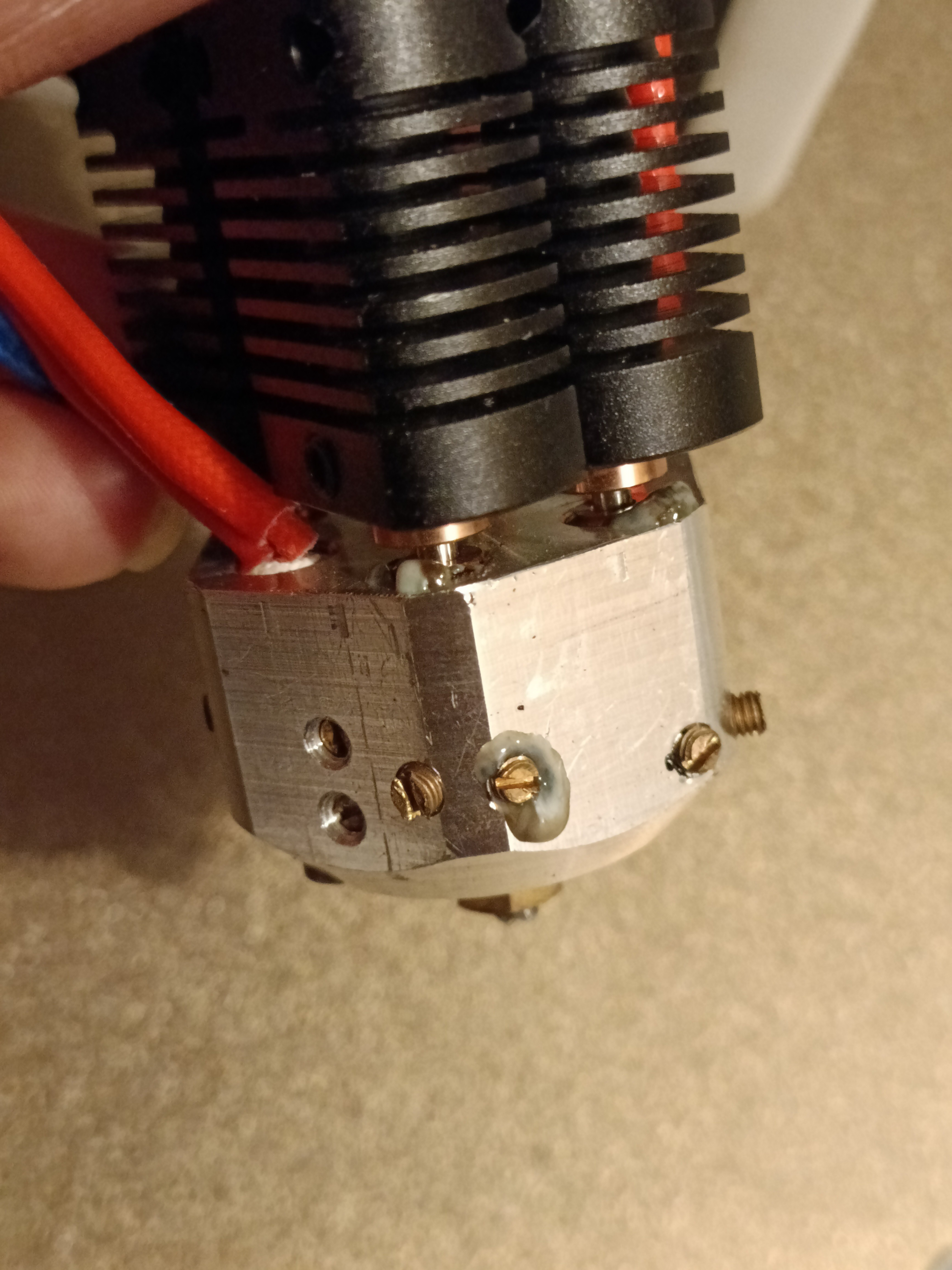
I looked at the virtual tools after and for some reason, T0 was set as a 9:1 ratio. Also, the wipe tower volume was too small to get proper transitions.
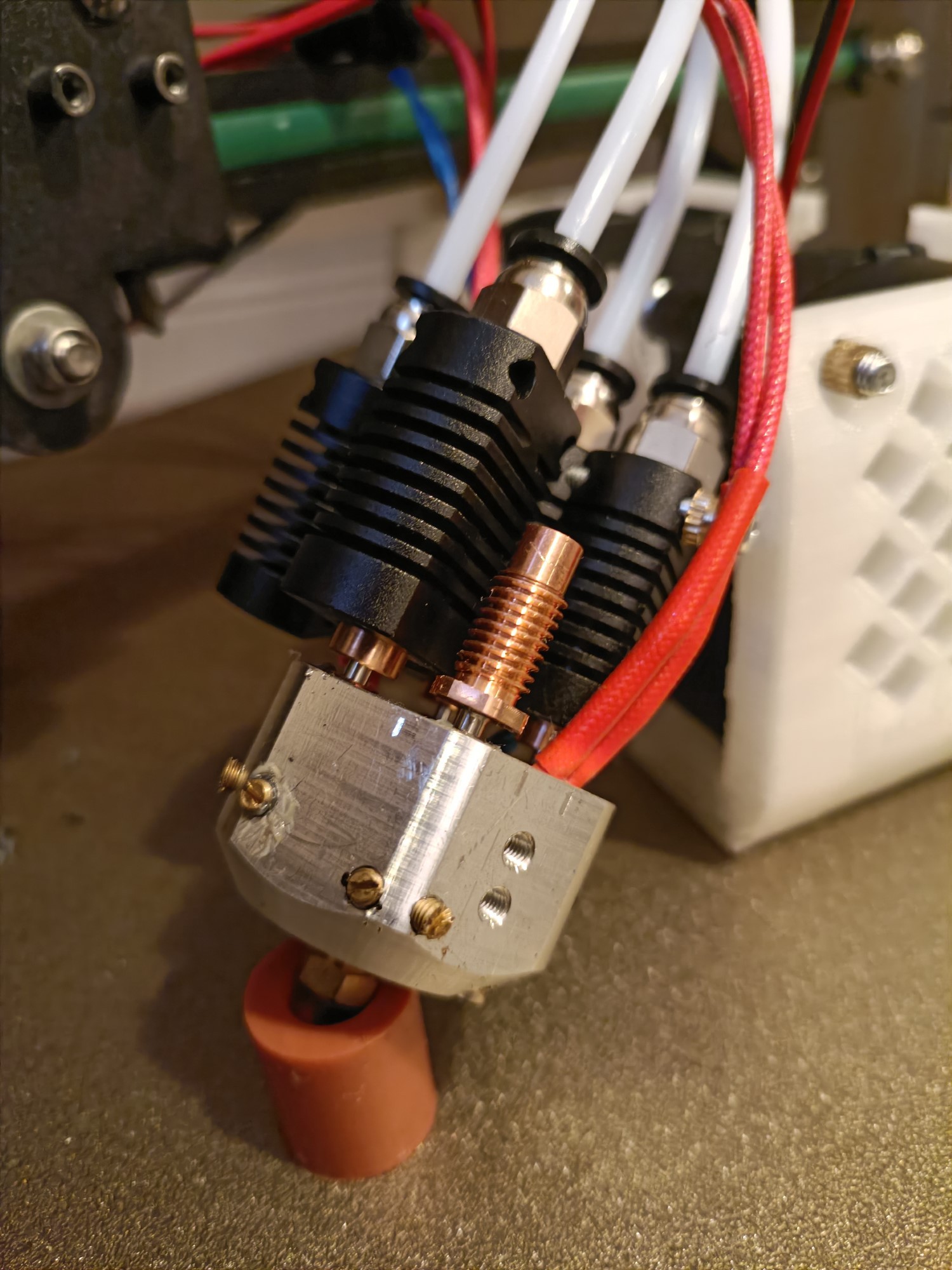
Second print test
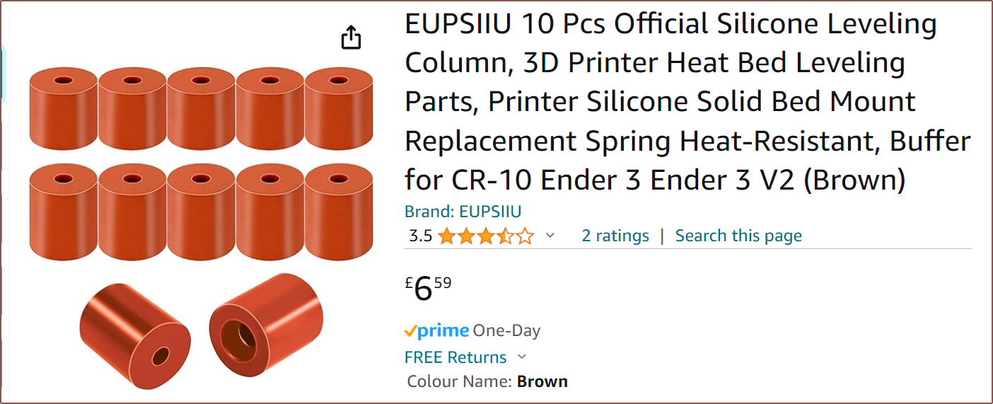
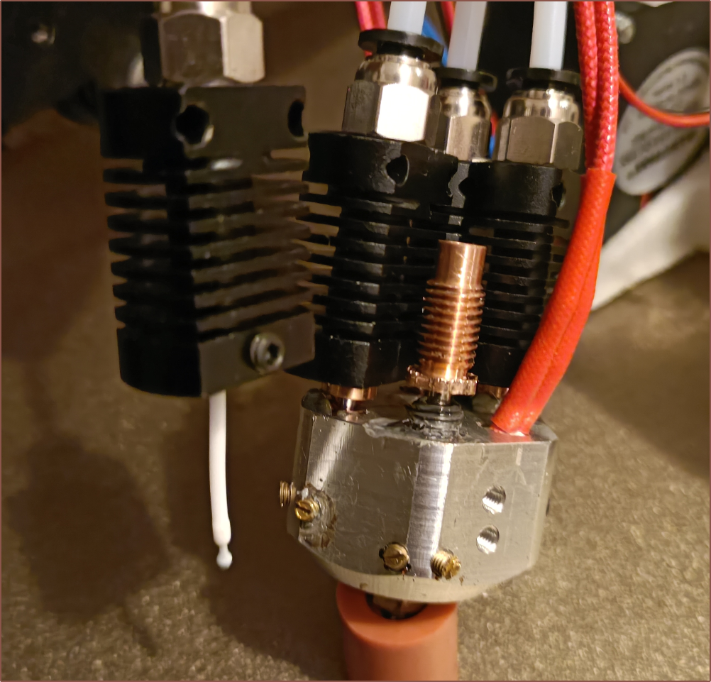
I thought that I might as well test to see if the heatbreaks just needed to be tighter or something, so with the help of one of the silicone levelling spacers, I swapped it out:
Then I sliced with a larger purge amount and even increased the amount of skirt length for extra measure:
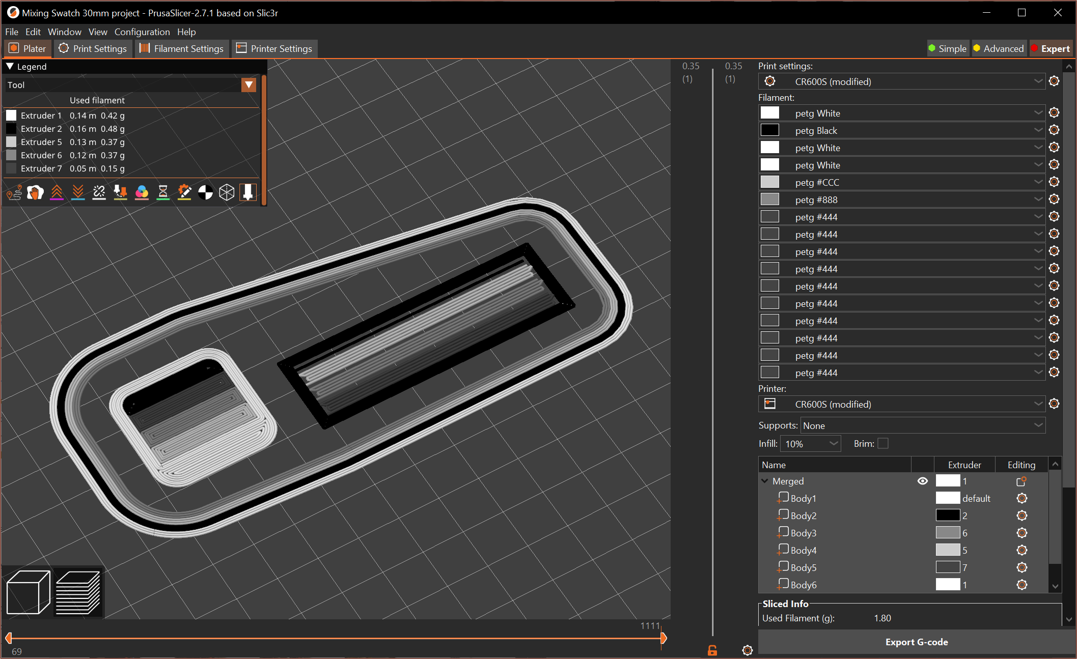
I found out something about M165 that it sets the mix for the active extruder (it's not a 1-line version of M163) and so added it to the filament gcode of each virtual tool (instead of the start gcode).
Expected ratios for vtools (starting at T0 = 1.):
- 1/0/0/0
- 0/1/0/0
- 0/0/1/0
- 0/0/0/1
- 0.7/0.3/0/0
- 0.8/0.2/0/0
- 0.9/0.1/0/0
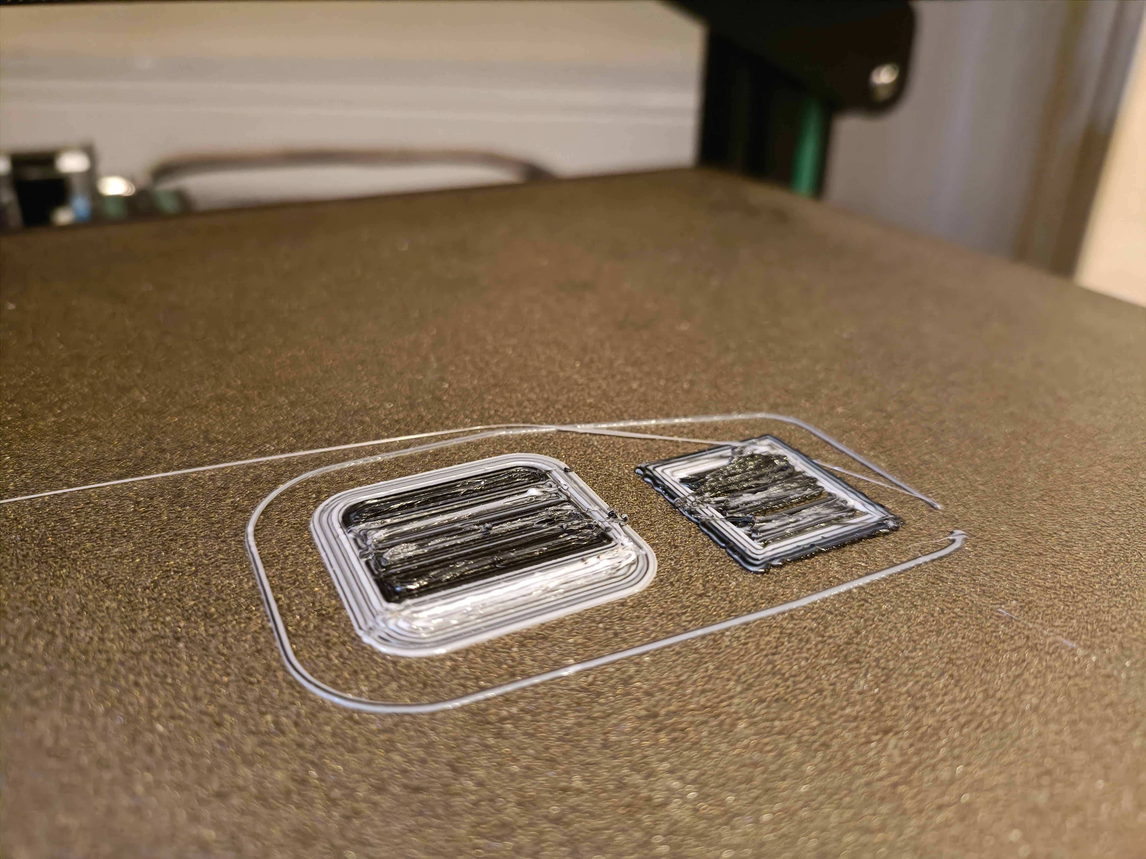
This is the result:
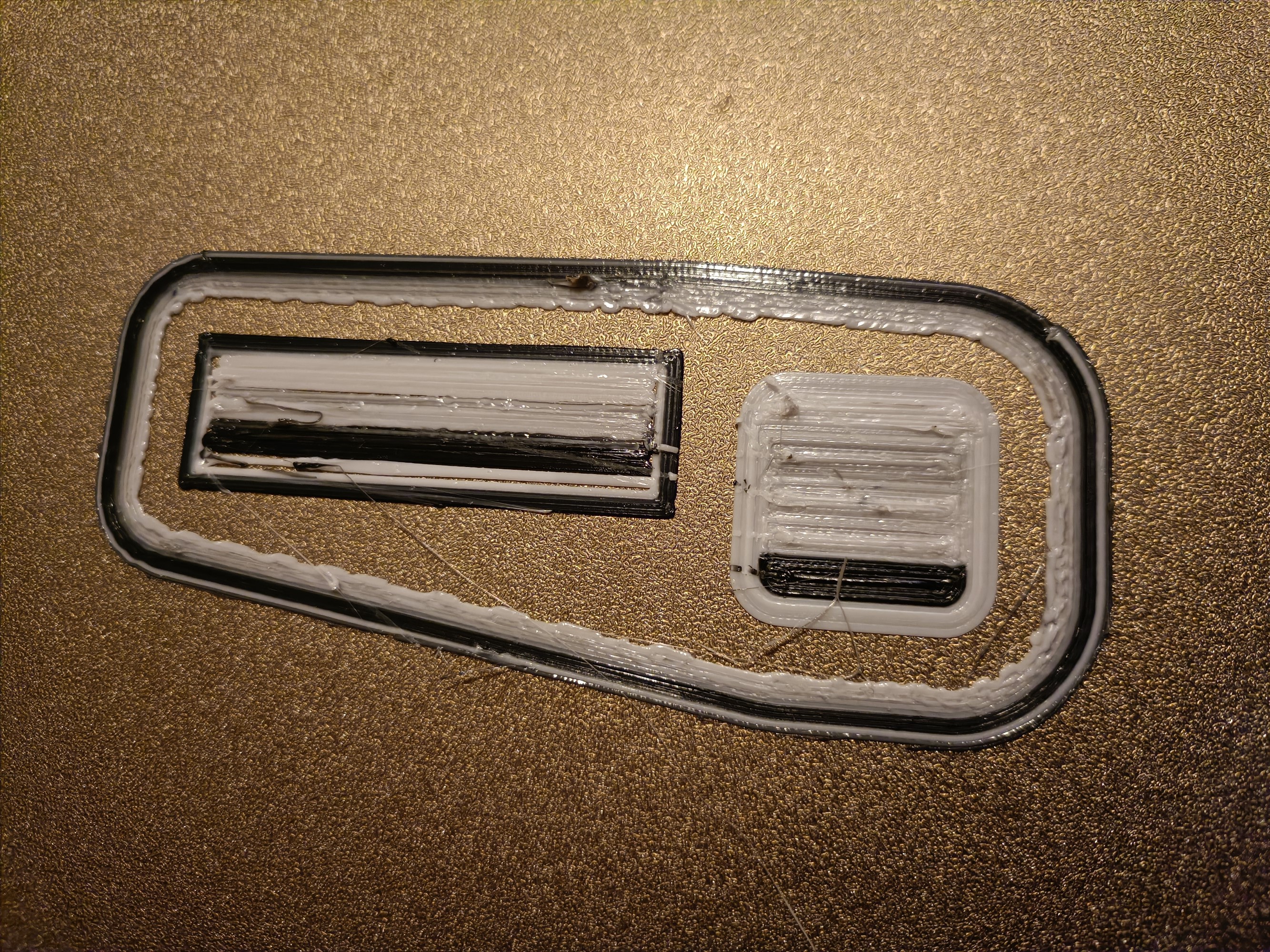
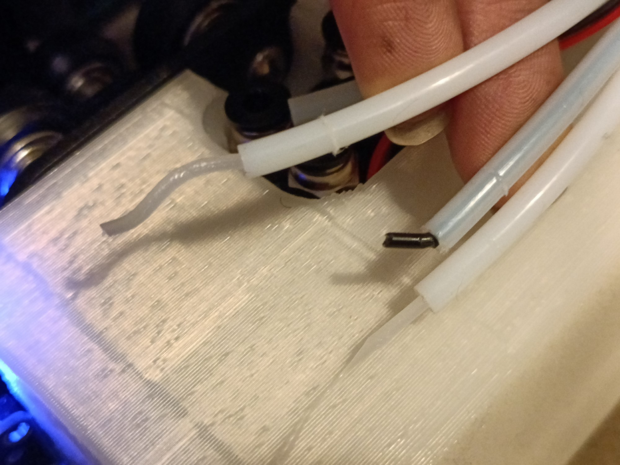
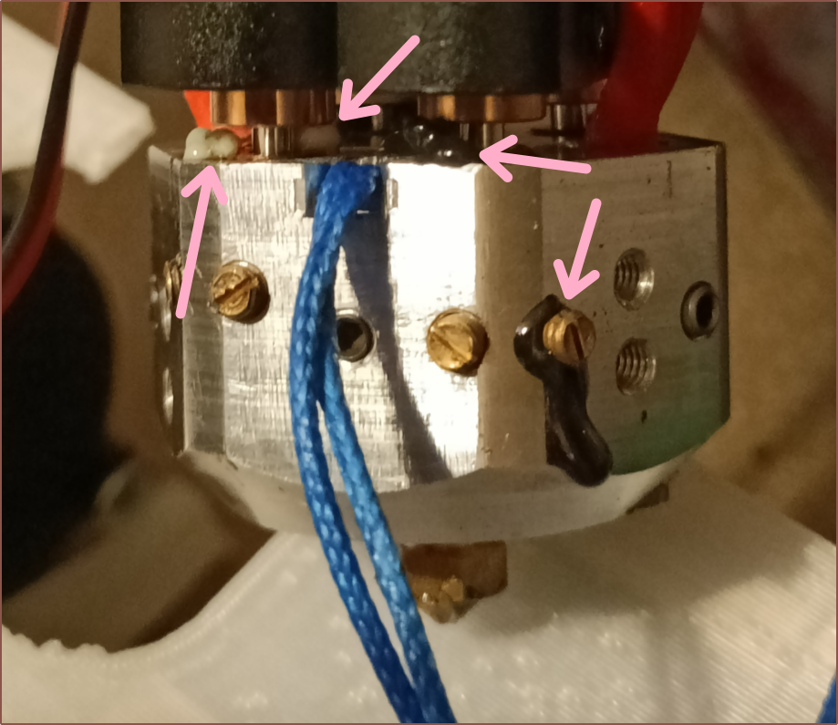
The hotend was in an even worse leakage state, with the experimental V6 heatbreak being awful:
Unlike the other 3, the filament was stuck in this one even when heated to 160C. I did manage to get it off though:
Conclusions
It's interesting that the first test was too black and the next test seemed kinda white. In terms of mixing, the results seem inconclusive. What I expect is that the overextrusion I observed had something to do with it. It could also be that material went in places it wasn't supposed to go, which also made me realise that I'm actually trying to get a "controlled leak" through the nozzle orifice and nowhere else. I saw some research a bit back which suggested that hotends work at 2MPa when printing, so it's more understandable how some can slowly ooze out.
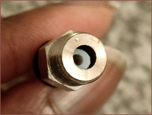
Even the nozzle and coaxial-insert threads are starting to leak now, which is not something that future machined designs have addressed. The deckingman approach, which is a machined-flat mating surface and plates where the M6 threads are tapped and then screwed ontop, sounds like the method to go, especially with a printed heatblock solution.
Also, I certainly need to be using compression fittings or that cool brass heatsink seen in the BotObjects 5-in-1-out hotend.
Discussions
Become a Hackaday.io Member
Create an account to leave a comment. Already have an account? Log In.
I was making changes to my Marlin config when calibrating for the SanBrother DDE's and found that my microstepping was set to 8 for extruders even though the steps/mm were the usual 16-microstep value of 418.5. It's possible that these test prints were trying to extrude 200% of the intended amount.
Are you sure? yes | no