 Dane Wagner
Overview
This project is made up of 3 main parts:
- Power supply
- LED controller
- the LED strings themselves
The LED strings used are WS2812B strings, commonly found on Amazon. The WS2812B RGB LEDs are individually addressable through a simple pulse-width-modulated one-wire serial protocol. Each LED is configured with 24 bits of color information: 8 bits each of red, green, and blue. The ones I purchased came in 5 meter strings of 150 LEDs.
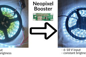
The WS2812B strings I used have a +5 V power rail, so I had to deal with getting a relatively low voltage out to a physically large array of LEDs. Each LED can pull about 40 mA at full power (though may pull more at peak; this is more of a typical measurement than a real max). For this project I used several LRS-350-5 60 A 5 V supplies. These supplies can be powered from 120 or 240 VAC. Distribution of such a low voltage over the large area required thicker copper cables. I would have liked to use 24 or 48 VDC distribution with a 5 V step-down to power every couple of strings, but I couldn't find supplies cheap enough to offset the cost of the copper cabling, especially when the 60 A LRS-350-5 was already extremely cheap.
The LED controller is made up of a BeagleWire iCE40 FPGA shield connected to a BeagleBone Black. The BeagleWire contains a iCE40HX4K with 16 kB of block RAM and 4 PMOD connectors (each with 3.3V, ground, and 8 I/O for a total of 32 easily accessible I/O). There are also Grove connectors, though I don't use them in this project as the I/O density is low. Of particular note, the BeagleWire has access to the BeagleBone's GPMC bus, which can be used to memory-map the FPGA into the ARM's memory space and efficiently transfer pixel data from the ARM to the FPGA.
The frame buffer is generated by a rust application running on the BeagleBone. When generation is complete, the application transfers control of the buffer to the kernel, where a custom kernel module DMAs the data over the TI GPMC bus to the FPGA. All of the block RAM on the FPGA is allocated to a memory-mapped FIFO that holds the frame buffer. Once a full frame buffer is transmitted to the FIFO, custom Verilog code automatically shifts that data out to each LED string in parallel.
Planning
My office is roughly 11 by 13 ft or 3.5 by 4 m (I know, I mix standard and metric measurements. I'm trying to wean myself off of Standard and convert fully to metric, but it's a work in progress). The LED strings have a fixed distance between LEDs of 30 LEDs per meter. The LEDs come in 5 m strips, and to minimize the amount of cutting and splicing I needed to do, I decided to run the LEDs along the longer 4 m length of the room. If I call each 4 m string a "row", the only remaining question is how many rows to install.
It would have been nice to have a square array with the same 30 LEDs per meter resolution in both directions, but I was limited by the amount of RAM in the iCE40. I decided that I wanted to be able to store a single frame buffer in block RAM. This isn't technically a requirement: I can pretty easily stream the data over the GPMC bus as the bus is significantly faster than the serial protocol used to configure the LEDs. I also didn't have an infinite budget for this project though, and setting the requirement that a full framebuffer fit in FPGA RAM ended up being a pretty reasonable constraint.
It turned out that each row could fit about 118 LEDs. Each LED has 24 bits of color data, or 2832 kb per row. The iCE40 HX4K theoretically has 20 4-kbit block RAMs for a total of 80 kbit. However, yosys and nextpnr both report 32 4-kbit block RAMs, and I can confirm that the total of 128 kbit of block RAM appears to work. Maybe the BeagleWire is actually using an HX8K, I don't know. Anyway, if we go with the 128 kbits of frame buffer, that gives us up to 46 rows of 118 LEDs each, or about 14 rows per meter. That was close...
Read more »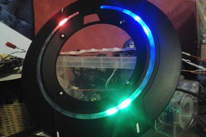
 Jan Mrázek
 Ken Yap