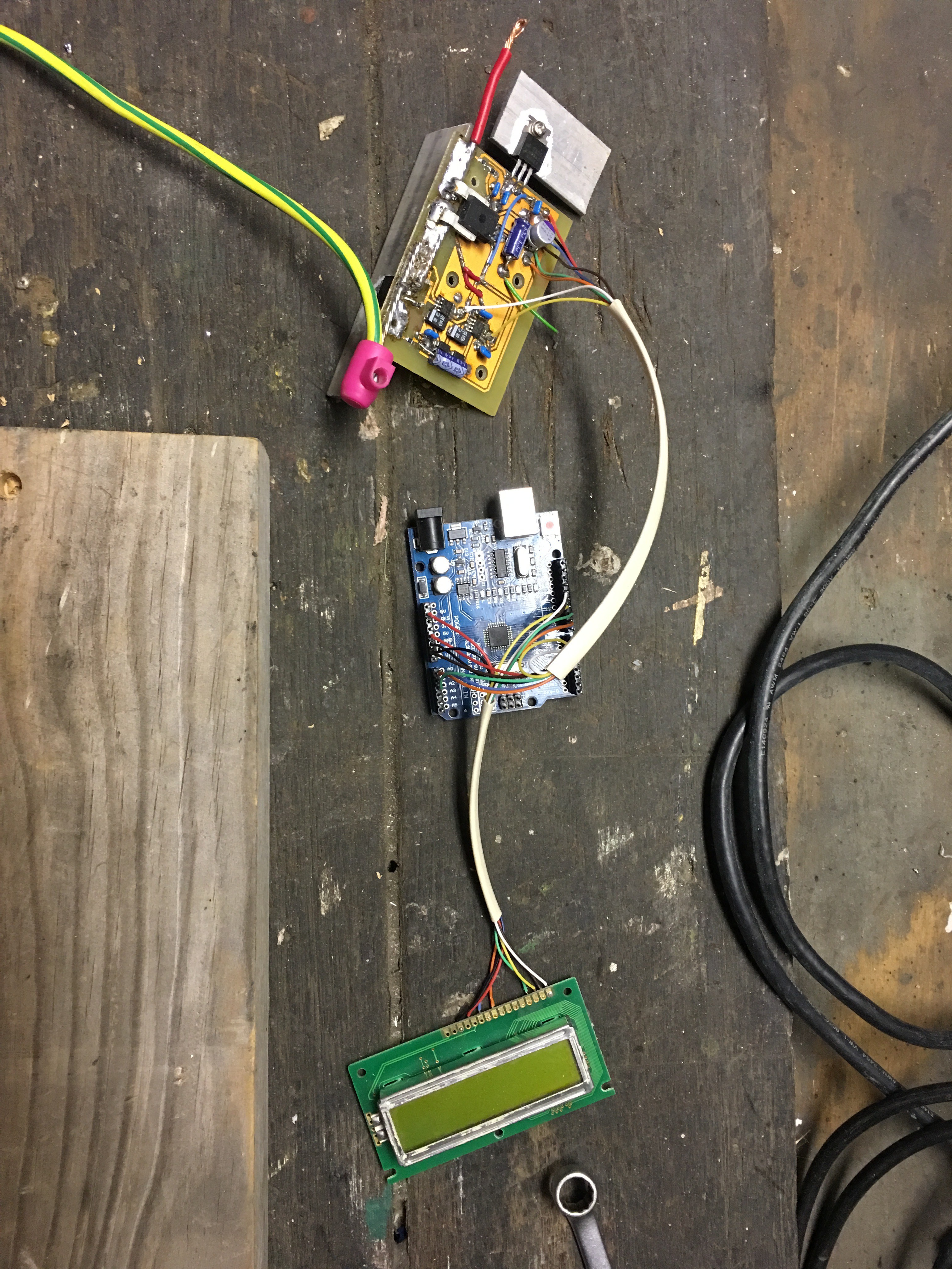
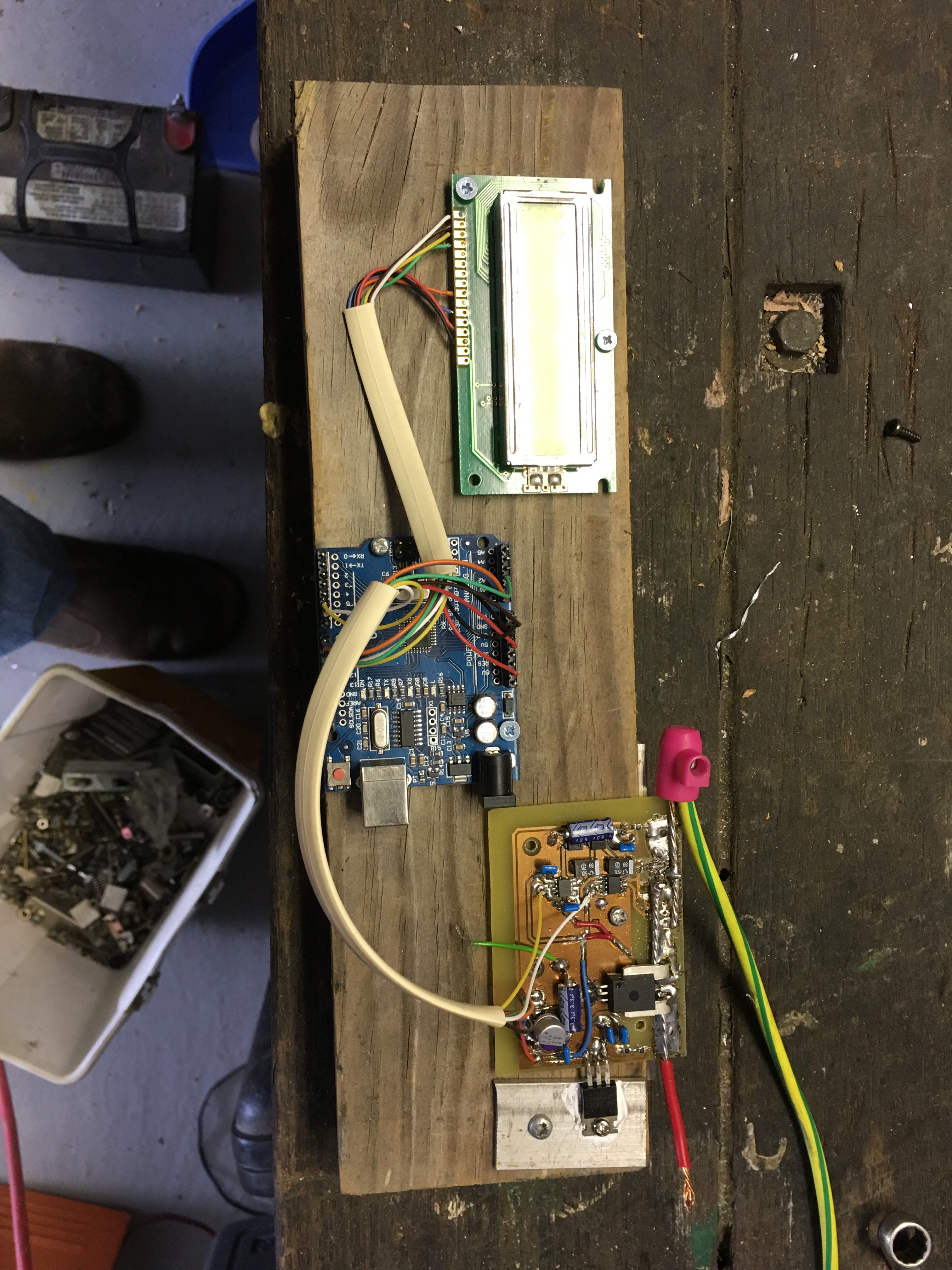
• Time to investigate

    Saabman01/20/2017 at 02:10 0 comments

    as this project has dragged on for much longer than it should have and we really needed to get a controller a quick look on eBay found me a suitably rated unit out of China for only $50 which is pretty close to theBOM costs for what I've been doing, so I bought one and have the batteries now under control.

    But I'm still curious as to why this project has the periodic lock up problem. So will continue working on it.

    To start with one issue that has plagued me has been broken wires between the modules, only becaus the 3 boards were floating in the breeze.

    So I've screwed them all to a lump of wood which will hold it all secure while I continue looking into it.

    Now it's a bit more secure I can lug it around a bit easier.

    some new firmware will be written to allow me to test the switching characteristics of the FET and drive circuit with out haveing to charge and discharge the batteries. I'll start with a square wave with a period of about 1 second and see what result I get.

  • erratic oppration

    Saabman01/13/2017 at 11:40 0 comments

    I had posted previously that I had another failed MOSFET and surmised it was due to excessive start up current of the Currentlimiting halogen globes.

    I had assumed that the FET had failed due as it was passing current despite the drive signal from the Arduino been low.

    I have subsequently discovered that some other factor is in play and that the FET has not failed but that something else is holding the gate high. It appeasr that a sudden increase of Drain current causes the FET to "lock" on untill power is removed from the circuit and it resets and begins to work again. - Further investigation required.

  • Further failure

    Saabman12/30/2016 at 19:03 0 comments

    I decided to persevere with the 24v supply and dug up another globe and added in parralell the 0.6ohm load resistor bank from my astratech battery tester.

    This allowed allowed around 25A of current to flow half way to my goal of 50A.

    But I still suffered a failure of the main FET. The device is supposedly rated at 100A continuous which should be adequate for the job. Perhaps the instantaneous startup currents that my test fixture will allow are in excess of the maximum that the FET will cope with.

    In both cases when the failure as occurred the FET has shorted from Drain to Source.

    In my circuit I have allowed for 2 FETS to be connected in parallel but have only been using one perhaps a second FET is required to deal with the instantaneous currents.

    I must check the turn on current of the halogen globes.

    Measuring the cold resistance of the two globes I'm using in parallel is around 0.1ohm 12/0.1 = 120A plus the 20A from the resistive load.

    That's 140 A inrush current so it looks like my test fixture is the caus eof the destruction.

  • Further failure

    Saabman12/30/2016 at 19:03 0 comments

    I decided to persevere with the 24v supply and dug up another globe and added in parralell the 0.6ohm load resistor bank from my astratech battery tester.

    This allowed allowed around 25A of current to flow half way to my goal of 50A.

    But I still suffered a failure of the main FET. The FET is a PSMN8R5 100PS good for 100V and 100A

    As a current limiting device I'm using 2 halogen headlights globes in parallel their cold resistance is approximately 0.1 ohm which gives a inrush current of 120A coupled with the 0.6 Ohm resistive load which means the FET has to deal with 140A

    I'll have to connect a globe to the scope and have a look at the length of time it takes to heat up and increase its resistance but given i can see the globe intensity increase it is a relatively long time

    The PSMN8R5 has a maximum pulsed current of 429A but ONLY for a maximum of 10uS im fairly certain my 140 for what would be 100's of mS is pushing the boundaries of the capability of the FET.

    I'll need to purchase some big power resistors and make a better current limiting stage to eliminate the surge currents which just won't occur in the real world application.

  • some success

    Saabman12/29/2016 at 05:06 0 comments

    I wired in a couple more Head light globes and got the current up to over 10A which was great again with no noticeable heating of the FET, But!

    Even by limiting the current to 10A the battery voltage rises quiet fast reaching 13.8V and then turning off and dropping back to 13V again very quickly - while everything seems to be happy Im not sure what he impact on the batteries will be as they will be pulse charged with quiet high currents.

    Im thinking a large inductor in between the switching FET and the current sensor would limit the current rise through the FET and into the batteries then I would need a diode to ground and I now have a buck converter :-)

    So much for a simple charge controller

  • destruction

    Saabman12/27/2016 at 11:59 0 comments

    kind of writing this up a fair way into the project - I have been happy with bench tests but limited to a supply of 2 A which is a long way from the real world.

    So to move to the next step i needed a much bigger supply something at around 600W at about 20V - (which is the open circuit voltage of the solar panels.

    hmm 2 x 12V batteries in series is only 24 close enough.

    So I wired up 2 100AH 12 volt batteries in series and connected to the solar input of the controller but to control things a little I put a 60W car headlight globe in series with the batteries to limit the current to about 5A or so, hooked up a battery to charge and all went well.

    With minimal heat sinking on the FET no noticeable temperature rise and things appeared to be going well so I decided to up the game a little and bypassed the globe.

    This is where things went wrong very quickly the battery supply was quiet happy to deliver in excess of 100A (the maximum reading on the current sensor ) before the FET went crack and removed its face - I really should have had something in place to limit the current to a more realistic 50A - given I have a 24V supply and need to drop to 14V.

    24 - 14 = 10V

    10/50 = 0.2 Ohm resistor capable of handling 500W should do the trick.

    alternatively if i replace one of the 12V batteries with a 6V that means I only need to drop from 18V to 14V.

    18 - 14 = 4V

    4/50 = .08Ohms

    looks like 11m of 2.5mm copper wire will do the job.