 George
All the design/details can be found on the github here: https://github.com/grob6000/hpbattery
In summary:
[ USB --> Schottky Diode --> ] TP4056 --> LiPo cell --> LDO Regulator --> Ideal Diode --> Calculator
[ Calculator pads --> Schottky Diode --> ]
Regulator increases efficiency??
I've performed a calculation for this battery pack design. The series linear regulator, by conventional wisdom, should result in lower battery life due to the wasted energy of (Vin - Vout)*Iout. However, the HP35 has an interesting (but not unusual for older / pre switchmode converter electronics) characteristic of disproportionately increasing current draw for increasing voltage input. The HP35 has a clever means of efficiently driving the LEDs:
"An inductive circuit method of driving the light-emit ting diodes is employed. Basically the method involves
using the time it takes current to build up in an inductor
to limit current, rather than using a resistor as is nor
mally done with LED read-outs. This saves power since
the only lossy components in the drive system are the
parasitic inductor and transistor resistances."
FIxed timing of the above driver, while being driven from the battery voltage directly, means the current consumption - while efficient relative to resistor current limiting - will still be subject to the non-linear voltage/current curve of the LEDs themselves.
This is bourne out by measurements of my HP35 - which consumes about 80mA at 3.6V but closer to 100mA at 4.0V - displaying "0." as per normal power on. With all the digits on the display on, this increases to closer to 100mA~140mA (actual measurements are in the github!).
The following table provides a comparison of the estimated power consumption for unregulated and regulated supplies (assumes regulator of 30mV VDO, see below), with the same battery voltage, showing although the regulated supply will dissipate some power in the regulator, the total consumed from the battery will be lower due to this non-ohmic load current.
| Vbat(V) | Vreg(V) | Iin (mA) | Pbat(mW) | Preg(mW) | Pcalculator | |
| Unregulated | 4.00 | N/A | 100 | 400 | 0 | 400 |
| Regulated | 4.00 | 3.6V | 80 | 320 | 32 | 288 |
But how low can you go?
Reducing the voltage into the calculator reduces the current (beneficially), so how low can I go? Turns out, the HP35 provides a handy low battery indication at 3.50V (alarmingly accurately 3.50V in my one at least!), where all the decimal points will turn on. Obviously we shouldn't operate below this too much, if only because according to the manual the calculator will not perform as expected / may make errors.
So our usable battery capacity will be limited by the point at which Vout gets to 3.50V.
A LiPo discharge curve has a relatively flat output voltage, which is not a lot more than 3.50V. In fact, at 80% full the battery will be about 3.9V, and at 20% will be about 3.7V. So if we want to ensure a good usable capacity, we need to ensure we minimise the dropout voltage of the regulator (also, this minimises its power dissipation from the point it reaches dropout voltage). Familiar linear regulators like the L7805, LM317 have a Vdo of around 1.5V. This would put our low-battery indication at 5.0V - higher than the 4.2V 100% capacity of the battery! As such, we need a very low dropout voltage regulator. Fortunately, parts such as the TPS73101 exist, which has a Vdo of as low as 30mV. Typically, such LDO regulators have lower current capabilities (in this case, 150mA, but this is enough for us).
With a 30mV regulator dropout voltage, a 1500mA LiPo battery, and the load characteristic of the HP35 measured, we can do a wee calculation - and the results show for 3.6V, I might get 16.1 hours run time, compared to 15.4 hours with no regulator! Winner.

The HP Charger
One key function I'd like is to be able to connect, use, and recharge from the original HP charger. These were designed for 500mAh 3S NiCd cells, and provide a constant current supply of 50mA. When you plug the charger in,...
Read more »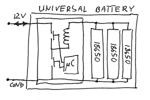
 Patrick Van Oosterwijck
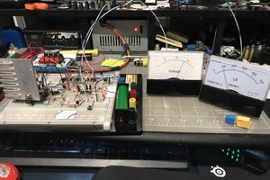
 ROFLhoff
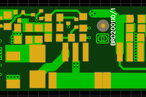
 Christoph Tack