Close
0%
0%

LiFePO4wered/9.6V

A USB chargeable 9.6V RC battery pack that will last for thousands of cycles

Similar projects worth following
Tired of RC toys that have batteries that last only for 10 cycles or so? So am I! Bought my boy an RC truck, it ran fine a couple of times and then the battery was dead. Not surprising: when I opened the "charger", all it had in it was a transformer and diode! That's no way to charge a battery!
So I decided to solve this problem and designed LiFePO4wered/9.6V. Based on LiFePO4 cells that last for thousands of cycles, with a built-in cell balancing BMS and chargeable with a standard 1A micro-USB charger you use for your phone or tablet. No more battery frustration, now let's play!

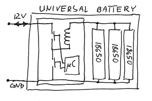
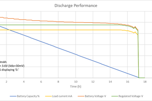
The topology of the pack is a stack of 3 series of 2 paralleled 14500 (AA) 550mAh 3.2V LiFePO4 cells. This results in a nominal voltage of 9.6V. During charge, the voltage will go up to 10.8V. An undervoltage protection feature will switch off the load when a single cell reaches 2.7V. In practice, that means the battery will turn off when the output voltage gets down to 8-9V. Due to the extremely flat discharge curve of LiFePO4 cells, the voltage will only drop to that level at the very end of discharge, so most of the 1100mAh capacity should be available.

The charger uses a booster current source, with shunt regulators set to 3.6V to limit the end of charge voltage on each cell. An MSP430 ultra low power microcontroller monitors the voltages of each cell to manage charge voltage and provide undervoltage protection.

  • 1 × MSP430G2131 16-bit ultra low power microcontroller
  • 1 × PAM2841 1.5A booster / current source
  • 1 × AZ431L Voltage reference used in passive balancing circuit

  • Unpopulated passives

    Patrick Van Oosterwijck11/10/2015 at 17:00 0 comments

    One may wonder why there are some unpopulated footprints for passives scattered around the board. These are more evidence of a lack of thorough engineering on my part when I quickly threw this circuit together. :)

    Initially I was intending to detect whether the battery is full during charge by checking whether all three shunt regulators have activated. This seems like a really elegant way to check for end of charge, and in theory, it is. The problem is the way I was trying to measure this condition. I was going to measure the base voltage of the bypass transistors, and since I am already measuring the top of each cell (which is connected to the bypass transistor's emitter), I could calculate the VBE and figure out if the transistor is on.

    Unfortunately, since I'm measuring voltages up to ~12V using an ADC reference of 1.5V, I am using voltage dividers with a pretty high ratio (5.11M and 680K). So the absolute tolerance of the top resistor makes a pretty big difference compared to value of the bottom resistor, even with 1% resistors. On top of that, since I'm measuring the VBE difference using two different resistive dividers, their tolerances can add up to make things worse. I calculated that for the expected 0.6V VBE value, my measurement error could be as high as +/-0.4V, worst case! Unusable when trying to design a reliable circuit.

    It might have been possible to monitor the VBE change during charge instead of using an absolute threshold, but that would assume we know the state of charge of the cells when starting a recharge. I didn't want to make any such assumptions since the system needs to work correctly when a full battery is plugged in as well.

    I decided instead to just determine the end of charge by measuring the voltage at the top of the battery. All cells need to be at 3.6V to have the top of the battery reach 10.8V. Of course, we have some measurement inaccuracy here as well, but it's only the inaccuracy of one resistive divider instead of the potentially cumulative inaccuracy of two. I calculated the inaccuracy to be ~250mV, and I deal with this by setting the threshold lower and having a "top off" timer that will keep the charge current going for 5 more minutes. This is safe because the shunt regulators will bypass the excess current and prevent the cell voltage from going above 3.6V.

    On the "cell empty" end, the measurement inaccuracy isn't a problem because of the big voltage change for an empty cell. The cell voltage shouldn't go lower than 2V, but a cell at 3V is just a drop away from being empty as well. So with my per-cell threshold at 2.7V, I should be safe in not switching the load off too early while making sure I don't discharge the cell too deeply.

    So with all of this, measuring the shunt regulator base voltages has become useless, so I'm not populating those parts. An added benefit is that it also reduces the leakage current through the voltage dividers.

  • Microcontroller power issues

    Patrick Van Oosterwijck10/23/2015 at 15:57 0 comments

    Another issue I've run into with this board was the microcontroller's power supply.

    Since the voltage range of a LiFePO4 cell is compatible with the voltage range of the MSP430 microcontroller, I powered the MSP430 directly from the bottom cell. This would ensure minimal power consumption, which is very important to preserve the battery's shelf life and to make sure the battery doesn't get discharged further once undervoltage protection kicks in. Since LiFePO4 cells also have very low internal resistance, I figured they would act like a big cap to shunt any noise that would be generated by the booster.

    Wrong! Well, maybe the cell works as a *big* cap in that it has similarly bad high frequency behavior. :) It certainly did not filter out switching noise and the MSP430 did not like it (oddly, the micro behaved kind of unpredictable and timers seemed to be running *faster*--maybe they were being clocked by the noise?). It seems the cells have very low internal resistance at DC, but the impedance increases with frequency.

    Hacking in a ferrite bead and extra filter capacitor on the back of the board solved the power supply noise problem.

    Another problem with the micro's power supply is that during charge, the extra 0.2V regulation voltage across the current sense resistor pushes the voltage at the top of the bottom cell up to 3.8V toward the end of the charge cycle. This is still well within the absolute maximum rating (4.1V) of the microcontroller, but outside the recommended operating conditions (3.6V). I'll probably revisit the power topology in the second rev.

  • Thought I'd quickly throw this together...

    Patrick Van Oosterwijck10/22/2015 at 23:11 0 comments

    ...and didn't do the engineering nearly as carefully as I should have. :) So the initial board has plenty of issues. But then, this started as something to do "in my spare time". That'll teach me to be more careful with my spare time.

    At first I was using a PAM2421 booster because it had a nice manageable SO8 package. But it didn't work. The reason is that it is a voltage regulator that was never intended to be used as a current source. It has an undervoltage protection feature that didn't allow the chip to ever start up.

    So I knew I needed to switch to a current source device, and a low cost option was to use an LED driver chip since they are produced in high volumes nowadays. The chip doesn't know it's pumping current through a stack of cells instead of LEDs. :) Unfortunately, I couldn't find any suitable/compatible options in SO8 package. I chose to use a PAM2841 in DFN package and make some small DFN to SO8 breakout boards. They work great!

    The balancing is done using AZ431L based shunt regulators, assisted by some beefy PNP transistors to shunt the charging current when a cell is full. Top it off with an ultra low power MSP430 to manage the whole thing and an output MOSFET to turn the load off when a single cell has reached its minimum discharge voltage and you have a nice battery pack that should last a long time.

    Work on the firmware is still ongoing but the prototypes look promising!

View all 3 project logs

Enjoy this project?

Share

Discussions

davedarko wrote 10/23/2015 at 11:52 point

hey, could you please also add a picture of the schematics? Nice project!

  Are you sure? yes | no

Patrick Van Oosterwijck wrote 10/23/2015 at 15:31 point

Unfortunately there are a bunch of things wrong with the current schematic that I used to create the PCB.  As I said, I threw it together too quickly.  The board has several hacks on it to make it work and the firmware is not completely fleshed out yet so there may be more hacks coming.  I'm using the current revision to figure it all out before I create a new rev.

I feel like posting a schematic now would be misleading and pretty much showing how NOT to do it. :)

  Are you sure? yes | no

Similar Projects

Does this project spark your interest?

Become a member to follow this project and never miss any updates