Close
0%
0%

Bipolar Membrane Energy Harvester

Harvesting energy from PH gradients

Similar projects worth following
Energy scarcity is at the root of many of the problems humanity now faces. This project demonstrates a new concept in energy harvesting, using ionomers to create a PH gradient, which may then converted to electrical energy by a PH Gradient Flow Cell.


The example devices are intended to be affordable and as simple as possible so that almost anyone can learn the concept and build these systems for their personal use. CAD models, instructions and component lists are included here and also on Github.


This work is licensed under a Creative Commons Attribution 4.0 International License.

This project addresses two challenges. First, it addresses the challenge of finding clean and sustainable alternatives to fossil fuels, by demonstrating a new method of energy collection with many desirable characteristics for grid-scale production like widespread availability, negligible downtime and no hazardous waste. Secondly, it addresses the difficulty in overcoming existing scientific dogma preventing the widespread adoption of these methods of energy collection by packaging this method in an example system which is as easy as possible for others to build and test for themselves, to prove for themselves that it works.

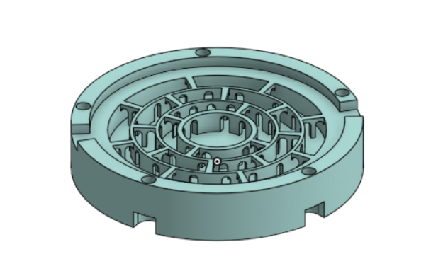
The Onshape projects for the 3D models can be found here and here.

The Github repository will be here when finished.

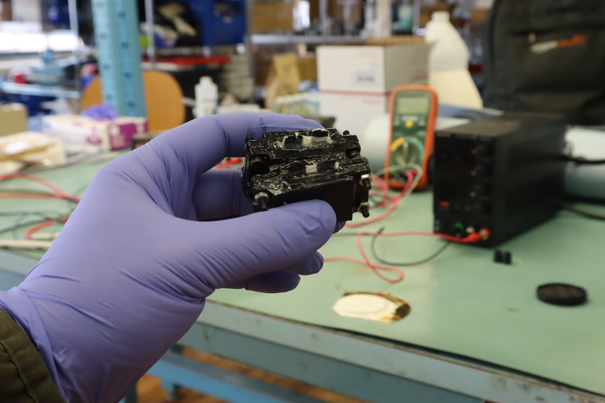
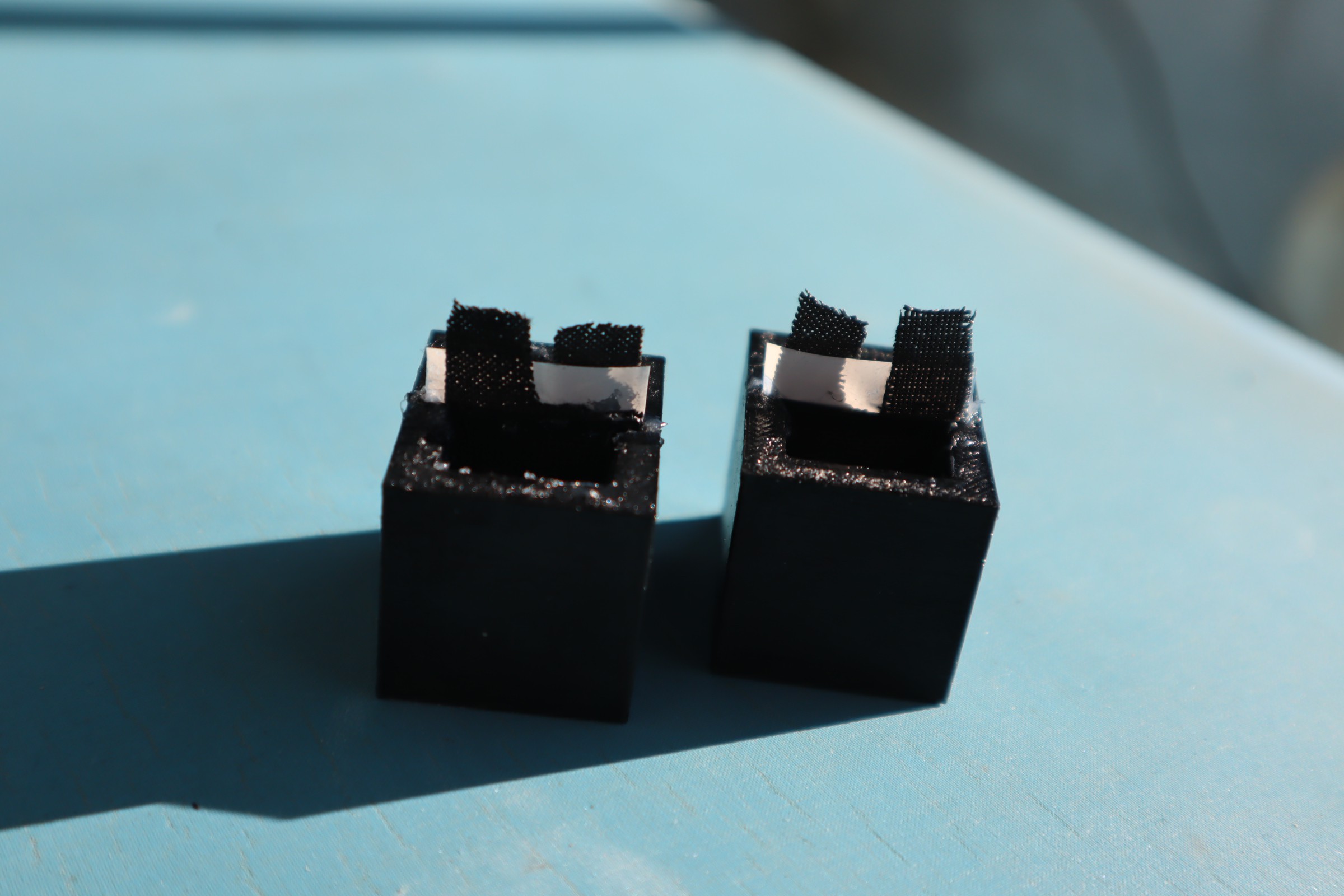
At present, this project provides instructions to make a small battery-like power cells like these:

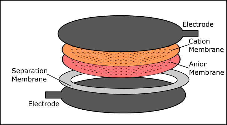
The Bipolar Membrane Energy Harvester uses a pH pump to drive a fuel cell to produce electrical power. It is well known in the literature that bipolar membranes create a very slight pH gradient in the volumes of water they separate. Usually this is viewed as an equilibrium/steady state phenomenon where the two liquids are at their steady state with respect to their boundary conditions, but when a flowback channel is added, as long as the diffusion rate is less than that of the bipolar membrane am appreciable pH difference remains despite the diffusion. This effect can be tapped to produce electrical power.

This avoids the second law of Thermodynamics, as opposed to violating it. The second law makes various assumptions about ergodicity and weak coupling which are not true for this system and a family of systems like it. If you're interested to know more you can read all about it in this book, chapters 3 and 7, Challenges to the Second Law of Thermodynamics by Capek and Sheehan, available on Amazon and elsewhere.

This project will provide instructions so you can prove to yourself that this works, and also so that you can use it to generate small amounts of electricity from ambient thermal energy. The pH gradient flow cell is easy enough to build and test, but the bipolar membrane device is very sensitive to contaminants so to prove nothing else is producing the power is somewhat involved.

Once we have demonstrated this proof, constructing a system that utilizes this effect is quite feasible. The power output will be small- just nanowatts for the proof of concept - but it can scale enough to run low-power electronics indefinitely.

Part 1: Prove out the concept

  • Develop a pH Gradient Flow Cell and demonstrate its operation
  • Develop a pH Gradient producing bipolar membrane device and demonstrate its operation

Part 2: Demonstrate electricity production

  • Integrate the bipolar membrane device and the pH gradient flow cell
  • Troubleshoot and refine the design: scale it up for use with microelectronics.

T-Battery-A-2023.pdf

Daniel Sheehan's recent paper on the theory of the concentration cell - a device very similar to the bipolar membrane device.

Adobe Portable Document Format - 292.65 kB - 09/26/2023 at 13:13

Preview
Download

Bottom Chamber.stl

Bipolar Membrane Flow Cell Chamber bottom

Standard Tesselated Geometry - 2.30 MB - 09/26/2023 at 08:12

Download

Top Chamber.stl

Bipolar Membrane Flow Cell Chamber top

Standard Tesselated Geometry - 2.45 MB - 09/26/2023 at 08:12

Download

Electrode Frame.stl

Bipolar Membrane Flow Cell electrode frame (print 2)

Standard Tesselated Geometry - 325.86 kB - 09/26/2023 at 08:12

Download

Chamber Cap.stl

Bipolar Membrane Flow Cell Chamber cap (print 2)

Standard Tesselated Geometry - 29.77 kB - 09/26/2023 at 08:12

Download

View all 15 files

  • 1 × ABS filiment for 3D printer Used for printing the pH gradient flow cell and MnO2 ink
  • 1 × Carbon Fabric Used for making the electrodes in the pH gradient flow cell and bipolar membrane flow cell
  • 1 × Celgard 3501 nonselective membrane Used in pH gradient flow cell and bipolar membrane flow cell
  • 1 × Manganese Dioxide Used in electrode ink
  • 1 × Carbon black Used in electrode ink

View all 27 components

  • Alternative Solutions for the Fuel Cell

    River Burgess03/18/2024 at 20:59 0 comments

    In conjunction with the recent redesign, we decided to look into alternative solutions to use in our fuel cell.  Specifically, we are looking to compare sodium carbonate, sodium chloride, and sodium borate with the currently used urea borate. 

    As when initially determining the suitability of materials for this device, we needed to confirm the solutions would not interact with any of the materials used. To do this, we soaked the materials in each of the three solutions. The process was similar to that used in testing materials described in parts 2-1 to 2-5 of the instructions. Unlike when first testing the materials, in this instance we only looked for changes in pH.

    Sodium Chloride (0.001 M) Sodium Borate (0.001 M) Sodium Carbonate (0.001 M)
    Sample Change in pH Sample Change in pH Sample Change in pH
    PETG 0.08 PETG -0.13 PETG 0.14
    Paraffin Wax -0.04 Paraffin Wax 0.09 Paraffin Wax -0.06
    Carbon Cloth 0.07 Carbon Cloth 0.13 Carbon Cloth 0.17
    Nylon Bolts 0.04 Nylon Bolts -0.16 Nylon Bolts -0.12
    Silicone 0.32 Silicone 0.44 Silicone 0.37
    None 0.01 None -0.07 None 0.12

    As shown in the table above, most of the materials did not react significantly to the different solutions. The only material that showed a significant pattern in changing the pH was silicone, which raised the pH slightly. This is not unexpected, as we did not use silicone in the pervious iteration of the fuel cell because it raised the pH in the initial materials testing as well. We chose to retest because we switched to an aquarium grade silicone to see if that would reduce the reaction, which it seems to have done. Additional testing should be done before we introduce silicone into the fuel cell.

    None of the potential solutions show significant reactivity to the main materials used in the fuel cell, with sodium chloride having the smallest change in pH for the materials overall. 

  • A Change in Fuel Cell Design

    River Burgess03/11/2024 at 20:48 0 comments

    In an attempt to improve the efficiency of the fuel cell, we decided to change our approach to the electrode assembly. As we described in the details for this project, two liquids on either side of the membrane are at their steady state with respect to their boundary conditions. We added a flowback channel, and aim to have a diffusion rate less than that of the bipolar membrane so there is an appreciable pH difference remaining despite the diffusion. 

    In order to minimize total path length for this otherwise probable event, we created a series of small holes in the bipolar membrane. The holes, spaced 4 mm apart with a diameter of .2 mm, will serve as many small flowback channels. Overall this will allow for a larger effective surface area, as flowback will be evenly spaced over the entire surface of the membrane. We hope this will show a marked improvement over other models, with the smaller path length translating into increased efficiency. 

    We are currently setting up a jig that will allow us to drill holes into the bipolar membrane using a .2 mm micro bit. Using a drill bit should minimize the disruption of the membrane interface over other methods such as piercing the membrane with pins.

    In addition to changing the membrane layers in the electrode assembly, there were some changes to the printed flow cell. We closed off the original center opening to the electrode assembly and added two notches opposite one another for the electrode tabs. 

  • Hackaday Prize Video

    Michael Perrone09/26/2023 at 13:56 0 comments

    Here's our official video for the Hackaday Prize competition:

  • A closer look at the new Bipolar Membrane flow cell version

    River Burgess09/26/2023 at 13:13 0 comments

    Another quick update for you! Part 3 of this project (The bipolar membrane flow cell) was completely reworked to make it easier to put together, as well as potentially producing a better pH gradient. Take a look at the updated instructions if you haven't already. We're seeing a pH difference of up to .5 in our latest proof-of-concept devices too. We'll be taking measurements periodically in order to test if this gradient breaks down over time. Keep an eye out for those tables to be posted in the coming weeks.

  • References

    Michael Perrone09/26/2023 at 12:55 0 comments

    We recommend studying nonequilibrium statistical mechanics to really thoroughly understand the experiments you can perform with the bipolar membrane devices. The best course I have found on this topic is by Prof. V. Balakrishnan on Youtube.

    Here you can find numerous relevant references and related topics of study, including other systems besides the bipolar membrane device, if you wish to try replicating those results as well. Needless to say, research in this field is still quite active.

    1. Bai, C., and A. S. Lavine. “On Hyperbolic Heat Conduction and the Second Law of Thermodynamics.” Journal of Heat Transfer 117, no. 2 (May 1, 1995): 256–63. https://doi.org/10.1115/1.2822514.
    2. Bar, Amir. “Linear Response and Onsager Reciprocal Relations,” n.d.
      Barletta, A., and E. Zanchini. “Hyperbolic Heat Conduction and Local Equilibrium: A Second Law Analysis.” International Journal of Heat and Mass Transfer 40, no. 5 (March 1, 1997): 1007–16. https://doi.org/10.1016/0017-9310(96)00211-6.
    3. Bright, T. J., and Z. M. Zhang. “Common Misperceptions of the Hyperbolic Heat Equation.” Journal of Thermophysics and Heat Transfer 23, no. 3 (2009): 601–7. https://doi.org/10.2514/1.39301.
    4. “Brownian Ratchet.” In Wikipedia, September 26, 2022. https://en.wikipedia.org/w/index.php?title=Brownian_ratchet&oldid=1112473938#cite_note-forced-3.  
    5. Callen, Herbert B., and Theodore A. Welton. “Irreversibility and Generalized Noise.” Physical Review 83, no. 1 (July 1, 1951): 34–40. https://doi.org/10.1103/PhysRev.83.34.  
    6. Čápek, Vladislav, and Daniel P. Sheehan. Challenges to the Second Law of Thermodynamics: Theory and Experiment. Dordrecht: Springer Netherlands, 2005. https://doi.org/10.1007/1-4020-3016-9.  
    7. Chemistry LibreTexts. “17.3: Brownian Ratchet,” January 17, 2021. https://chem.libretexts.org/Bookshelves/Biological_Chemistry/Concepts_in_Biophysical_Chemistry_(Tokmakoff)/04%3A_Transport/17%3A_Directed_and_Active_Transport/17.03%3A_Brownian_Ratchet.
    8.   D’Abramo, Germano. “On the Exploitability of Thermo-Charged Capacitors.” Physica A: Statistical Mechanics and Its Applications 390, no. 3 (February 1, 2011): 482–91. https://doi.org/10.1016/j.physa.2010.10.031.
    9. D’Abramo, Germano. “Thermo-Charged Capacitors and the Second Law of Thermodynamics.” Physics Letters A 374, no. 17 (April 12, 2010): 1801–5. https://doi.org/10.1016/j.physleta.2010.02.056.
    10. Danageozian, Arshag, Mark M. Wilde, and Francesco Buscemi. “Thermodynamic Constraints on Quantum Information Gain and Error Correction: A Triple Trade-Off.” PRX Quantum 3, no. 2 (April 26, 2022): 020318. https://doi.org/10.1103/PRXQuantum.3.020318.
    11. Démoulin, Damien, Marie-France Carlier, Jérôme Bibette, and Jean Baudry. “Power Transduction of Actin Filaments Ratcheting in Vitro against a Load.” Proceedings of the National Academy of Sciences 111, no. 50 (December 16, 2014): 17845–50. https://doi.org/10.1073/pnas.1414184111.  
    12. “Entropic Force.” In Wikipedia, September 7, 2023. https://en.wikipedia.org/w/index.php?title=Entropic_force&oldid=1174355238
    13. Ethier, S. N., and Jiyeon Lee. “The Flashing Brownian Ratchet and Parrondo’s Paradox.” Royal Society Open Science 5, no. 1 (January 24, 2018): 171685. https://doi.org/10.1098/rsos.171685.  
    14. Ghosh, Aritra, Malay Bandyopadhyay, Sushanta Dattagupta, and Shamik Gupta. “Quantum Brownian Motion: A Review.” arXiv, June 5, 2023. https://doi.org/10.48550/arXiv.2306.02665.
    15. Higashi, Torahiko L, Georgii Pobegalov, Minzhe Tang, Maxim I Molodtsov, and Frank Uhlmann. “A Brownian Ratchet Model for DNA Loop Extrusion by the Cohesin Complex.” eLife 10 (n.d.): e67530. https://doi.org/10.7554/eLife.67530.  
    16. Hoyuelos, Miguel. “Entropy of Continuous Markov Processes in Local Thermal Equilibrium.”...
    Read more »

  • Featured on Alienscientist

    Michael Perrone09/26/2023 at 01:15 0 comments

    We tested the fully assembled bipolar membrane flow cell and posted it to my friend Jeremy's channel. You can see the preliminary results here:

    We got picowatts of power so far, which is similar to preliminary results at Prof. Daniel Sheehan's lab at U.C. San Diego with their devices. The result is quite repeatable. So far the device is unoptimized so we expect a factor of 2 or 4 more power from an optimized device. We'll add our final video for the competition in the morning, as well as some supplementary references.

  • Proof-of-Concept device with a low pH

    River Burgess09/20/2023 at 14:42 0 comments

    We have a quick update for you, to show an interesting result we had with one of our proof-of-concept devices. 

    The bipolar membranes in these devices need to be soaked in a dilute solution of sodium hydroxide because the anion membranes have a quaternary ammonium ion, and they use chloride ions for shipping the membrane. This would make them acidic in our experiments if they are not neutralized.

    We ran the experiment without pre-soaking the device and got measurements that were extremely acidic, though there was still a pH difference. There were two devices, one with the anion membrane facing the outer cylinder and one with it facing the inner cylinder. For the device with the anion membrane facing the outer cylinder, the outer measurement was a pH of 2.471 and the inner measurement was 3.264. For the one with the anion membrane facing the inner cylinder, the outer measurement was 3.382 and the inner measurement was 2.475.

    All these were much more acidic than the 6.776 pH of the solution used, due to the HCl forming from the chloride in the membrane. We do see a much larger pH gradient than what is expected for this device, which should have fully equalized. We're not sure if the chamber directly exposed to the anion membrane had a lower pH because the membrane was not neutralized, or if the pH gradient we are trying to demonstrate is exaggerated at a lower pH. We plan on exploring this idea at a later date, but wanted to share the interesting results.

    Keep an eye out for a much larger update, including a complete overhaul of the bipolar membrane flow cell, set to come out in the next few days.

  • Materials Testing

    River Burgess07/04/2023 at 03:01 0 comments

    Over the course of developing the Bipolar Membrane Energy Harvester, we used many different materials. We decided to put each and every one of the materials used through a series of tests to determine its reactivity to the various solutions we’ll use in the Energy Harvester.

    Our goal is to find materials that will serve our purpose without interfering with the experiment. It’s imperative that any materials used are non-reactive under the experimental conditions because with this particular design, we are looking for very small amounts of energy. Any unintended interactions could overwhelm the effect we are trying to measure.

    For our purposes, we decided to test each material sample for a few different things. All the samples had their pH tested, while those potentially containing ammonia, chloride, or manganese each had those tests run as well. Any discrepancy between a control and a sample is indicative of an unfavorable reaction.

    A more in-depth look at how to run the materials testing can be found in Part 2 of the instructions. Here we will discuss the materials themselves, and what sort of patterns we saw when testing them. To give a brief explanation about how we ran the tests: A small amount of each sample we wanted to test was put into four different glass vials. Each vial was filled with a different solution. Two vials of each solution were also made with no material added to act as a control. They were left for a week before measurements were taken. After the samples were put in fresh solution and allowed to sit for another week.

    Table 1: Results from each round of testing

    In table 1, you can see the measurements taken for each of the different samples tested. Samples marked in red vary significantly from what was expected. Some of the materials, like the epoxy, we expected to react. Other samples were more of a surprise and were the reason we took time to test each of the materials. Kimwipes, for example, had a major impact on the pH and chloride of most of the samples. We had assumed they were unreactive, so after learning this we made sure to adjust our methods accordingly and rinse any components that came in contact with the wipes before using.

    Other materials became less reactive after the initial soaking, which means they could be used if we were careful. We also saw that the urea solutions seemed less reactive.  That was one of the major reasons we ultimately chose urea borate for our first test producing a pH gradient with the bipolar membranes.

    Ultimately, the diligence used when testing any and all materials allows us to be more confident in our results. The end goal of this testing was to eliminate potential interference with the effect we are trying to measure.  

View all 8 project logs

  • 1
    Part 1: Flow Cell using a PH gradient

    This flow cell generates electricity by differences in electrode potential in manganese dioxide over a PH gradient, like a fuel cell that uses acids and bases instead of oxygen and fuel. This type of technology, albeit probably with different electrode materials optimized for the task, is being investigated for use in concentration gradient cells for collecting power from salinity gradients at the mouths of rivers as they feed into the ocean.

    To build one, you just need to separate two bodies of water with a membrane which restricts the diffusion rate, then place the two electrodes on each side of the membrane, as close together to each other as possible. In the above paper and in our implementation, this is done with carbon fabric and a Celgard 3501 nonselective membrane held close together by a frame for mechanical reinforcement. In the paper this was chosen because it is more cost-effective and robust than ion-exchange membranes used for the same application, at the cost of some efficiency. If you do choose to use an ion exchange membrane instead of Celgard, the rest of the instructions are the same, just make sure it never dries out once assembled, or it may deform and tear or form microcracks.

    The container for the bodies of water can be any shape, size or configuration as long as the membrane and electrode materials are cut to size and the electrodes can be electrically contacted (ideally in a way that keeps the electrical contacts from getting wet with the electrolytes, which may corrode the contacts). For best results, the membrane and electrode stack should seal well to prevent any leaks between the two bodies of water from going around their edge: in our implementation we do this with silicone. We have provided some 3D models to construct the following example system:


    This device holds some acidic and basic water in two compartments, with a separator in between them. The carbon fabric electrodes have very different electrode potentials in the two solutions, and the membrane allows ion conduction, producing power in a manner similar to a fuel cell. The preparation is simple, but with a few nuances worth mentioning:

    1. Prepare the electrodes
      1. The electrode ink recipe is the same as described in part 3 of these instructions. It may be easier to prepare in larger batch sizes depending on the sensitivity of your weighing scale. The ink needs to be shaken before each use, making sure to thoroughly break up any clumps. Also make sure you store the ink in a container that will not allow the acetone to evaporate over time, and/or mark the acetone level  with a pen for long-term storage so the ink can be reconstituted.
      2. Cut the conductive carbon fabric to size. For our system that ends up being 20mm by 20mm square, but you'll want to leave a tag roughly 5mm by 5mm above the main electrode to serve as an electrical contact. It may be easier to cut the carbon fabric at 45 degrees to the way it is cut when received, because this helps prevent fraying which can lead to shorting of the electrodes in later steps in the assembly.
      3. Seal the electrical contact tag: once wet the carbon fabric can wick water up to the electrical contacts, where evaporation and corrosion can produce a false signal. To avoid this we apply a few drops of superglue at the interface between the 5 by 5 mm tag and the 20 by 20 mm electrode surface. This ensures the capillaries between the threads are all sealed up, preventing wicking.
      4. Shake the ink thoroughly before applying it to homogenize, then with a pipette or eye dropper, apply 4-5 drops per 20mmX20mm electrode surface and spread it to coat evenly. Then allow the freshly prepared electrode to dry.

      The process should look something like this:

    1. Assemble the remaining components
      1. The separator membrane should be cut slightly wider than the electrodes to help prevent shorting between the electrodes. If the electrodes are a little too big, you may want to trim them and stack the separator and electrodes to check that the separator
      2. 3D print the provided frame and container files.
    2. Assemble the cell
      1. Stack the cell components: frame, electrode, separator, electrode and frame.
      2. Carefully
        apply a small amount of silicone around the edge of the assembly, avoiding the electrical contacts. Make sure not to get any silicone on the exposed electrode surfaces. It may be prudent to allow this assembly to dry for a few hours before proceeding, so that it holds together when being inserted into the container, but it isn't so dry that the silicone has the chance to delaminate when sheared.
      3. Apply a bead of silicone to the groove in the container.
      4. Insert the frame assembly into the groove in the container.
      5. Allow the assembly to dry for 1 hour then test for water tightness (the electrodes will initially be hydrophobic). If there is a leak, add more silicone where needed. It is better to do this before the other silicone dries completely, to ensure a strong mechanical joining.
      6. Allow the silicone to fully dry overnight.
      7. Apply a small drop of dish soap to each electrode. This will get the carbon fabric electrodes to wick water when the acid and base solutions are added.
    3. Add Solution and measure results
      1. Prepare two solutions, one of sodium hydroxide and one of acetic acid, both at 1 M concentration. You will want approximately 20-25 mL of each solution
      2. Carefully use a pipette to fill each side of the flow cell with different solutions.
      3. Allow the electrodes to soak up the solution.
      4. Attach alligator clips to each of the electrodes and measure the voltage
  • 2
    Part 1B: Alternitive options

    For the pH flow cell, other substances besides sodium hydroxide and acetic acid can be used. The article linked at the beginning of the instructions explains how to use waste carbon dioxide to produce a pH difference in the solutions. Other options would include any solutions with a pH difference that do not damage the other components.

  • 3
    Part 2: Materials Testing and Proof-of-Concept

    Though you do not need to build the proof-of-concept device in order to make the flow cell in part 3, we do recommend that if you want to thoroughly validate the effect observed, you go through the materials testing process for all of your materials, even if they are the same type listed here. This can eliminate any materials that could interact with the solutions used in this device and find possible sources of contamination. This is also useful if you want to construct a similar flow cell out of different materials

    1. Preparing solutions

      When preparing the solutions, avoiding contamination is imperative. Wash your gloves first in water, rinsing off the coating, and then in deionized water, to remove any contaminants. Even powder-free gloves have a coating on them. All solutions should be prepared with deionized water, and the materials should be the purest version you can get.

      There are four different solutions tested: Ammonium Chloride, Sodium Chloride, Urea Borate, and Urea Monochloride. All the solutions are at the same concentration of 0.001 M. You should make at least 30 mL per sample tested of each solution, with an additional 50 mL to set aside as a control. This will give you enough solution to test each for signs of reactions or contamination.

      Preparing solutions at the low concentration of 0.001 M means measuring out materials at a fraction of a gram. If you do not have a scale sensitive enough for this, prepare a more concentrated solution and dilute as needed. These concentrated solutions can be used to make the solutions for the second soaking if they are kept sealed and free of contamination.

      For the ammonium chloride and sodium chloride, it is sufficient to add the materials and mix until dissolved. It is important to get pure sodium chloride, as most table salts have additives like iodine. The preparation for both urea compounds is more time-intensive, as they need time to react fully before use. The urea borate and urea monochloride are made by mixing urea with boric acid, and urea with hydrochloric acid, respectively. The goal is to reach a neutral PH.

      For making urea monochloride, start by making a solution of hydrochloric acid at the desired concentration. Because hydrochloric acid is a much stronger acid, more urea will be needed to neutralize it. Expect to need to add an order of magnitude more urea than HCl. Once prepared, add urea to the HCl solution. Start by adding 10x as much urea as you did HCl. With that amount of urea added, the reaction will start. It’s endothermic, so the solution gets cold. Use a hot plate to bring the solution to 80 C and allow it to cool. Be sure to cover the solution and add back any water lost during heating. Once the solution is back at room temperature, measure the PH. It will likely still be acidic at this point. Repeat the heating process, adding urea each time, until you get a PH at or near 7. Let the solution sit overnight, as it may continue reacting. Re-measure the PH and if it is still around 7, the solution is ready for testing. If not adjust as needed. As a note: it is better to have an excess of urea than to have unreacted acid but try not to significantly overshoot.

      The urea borate solution follows the same procedure as the urea monochloride solution, with the only difference being much less urea is needed. Boric acid is much weaker, so start with 5x as much urea as boric acid, and it to be much closer to neutral after the first round of heating.
    2. Preparing Samples

      Each material used in the final device needs to be tested for potential reactivity and contamination. Every material is tested in each of the four prepared solutions, and the results will impact which materials and solutions will be used in the final device.

      Start by taking four small samples of each material and putting them into separate glass containers. Make sure the seal on the container is tight, and the lid does not have any metal components. Samples should be in the condition they’ll be when used in the device (fully cured, run through the printer, etc.). You’ll need at least 4 extra empty containers to use as a control, but it’s best to have 8, two for each type of solution, as backup.

      Fill one container of each different sample with one of the solutions, so you have all combinations of solutions and samples prepared. Each sample should be in at least 30 mL of solution, in order to have enough for testing. Once the samples are prepared, set them aside for at least a week, allowing any reactions to take place.
    3. Measurements

      You’ll make different measurements based on the materials and solution for each sample. The PH will be measured for all samples, chloride ions will be measured for all samples except the ones in urea borate, and ammonia will only be measured for the samples in ammonium chloride. Manganese will only be measured in the samples of manganese material.

      For all the samples, first measure the PH of each uncontaminated solution (the containers set aside without materials added). This will be your base PH to measure against. Be sure to rinse the PH probe with deionized water between each of the measurements to prevent cross-contamination.

      Once the base PH is established, measure the PH for each of the samples made. The further they are from the base PH, the more likely it is that the material reacted with the solution. Any reaction is unfavorable, so, if at all possible, eliminate use of any material shown to have reacted.

      The same procedure is followed for the chloride test, except you do not need to test the urea borate, as it does not contain chlorine. Establish a base level for each set of samples and compare them to the levels tested. The ammonia test is done in the same way, but only for the ammonium chloride samples. Manganese tests need only be run on samples containing the manganese materials.
    4. Second Soak

      Once the materials have all been tested, drain the remaining solution and refill with fresh solution. Be sure to use the same solution the sample was initially soaked in. Allow it to soak for an additional week and repeat the measurements. Some materials won’t react during the second soaking, and those materials will be fine to use after being soaked.
    5. Choosing Materials

      When deciding which solution and material to use for the final devices, you want to look for ones that do not show significant changes in any of the measurements from the base test to the materials test. Our results showed the materials were best used with the urea borate solution, so that is what the instructions will reflect. If you choose to use a different solution, substitute further mentions of urea borate with your chosen solution.
    6. Assembling Proof-of-Concept Device

      1. Preparing Components

        Components for the proof-of-concept device found in the files section. There are four pieces: the inner cylinder, the outer cylinder, the lid, and the base. All the pieces were designed to be printed successfully without need for supports, as supports for the inner and outer cylinders in particular are difficult to remove .

        Once printed, each piece should be handled with rinsed gloves, following the same precautions as seen in step 1. This is to prevent skin oils and other contaminants from getting on the parts. All parts, along with the paraffin wax that will be used to seal them, should be soaked in the urea borate solution. We found this solution to be the best option for this experiment based on the materials chosen. Other solutions may be used depending on the materials and their potential reactions.

        Once soaked for a minimum of two days (though a week is preferable), The components and wax can be removed from the solution. Remember to wear rinsed gloves when handling all materials for this experiment. The assembly surface should be rinsed with deionized water to remove contaminants. It should be made of a material like silicone or glass, which won’t transfer any contaminants with contact.
      2. Assembly

        To assemble the device, first cut both anion and cation membranes into a rectangle that’s 30 mm by 110 mm. You should then layer them together, with the thicker plastic backing on the outside. They should stick when pressed together, if they don’t then one is likely backwards and should be flipped around.

        Once you have the bipolar membrane layered, remove both plastic backings, and wrap it tightly around the inner cylinder. There should be enough for a small overlap at the seam. This overlap needs to line up with the side of the cylinder that is solid, with only one small hole.

        Open the outer cylinder and carefully slide the inner cylinder with the membranes into the space. There should be enough flex in the outer cylinder to give clearance to the inner one, so the membranes don’t get caught and fold or tear. Line up the seam on the membranes with the seam on the outer cylinder, so the spokes on the inner and outer cylinders line up as well.

        Melt the paraffin wax in a clean glass container that was rinsed with deionized water. Cover the bottom in a thin layer of melted wax, then put in the cylinder assembly. Line the cylinders up with the grooves on the bottom and push it on fully. Do the same with the cap, allowing the wax to cool slightly so it does not run in to the device. Use a small amount of wax to seal the seam of the outer cylinder.
      3. Second Soak

        After the device is assembled, it needs to be soaked in a dilute sodium hydroxide solution to activate the membranes. Use a pipette to fill the device with a 0.005 M sodium hydroxide solution, alternating between the inner and outer sections until completely full. Lightly shake and tap the device to make sure there is no trapped air.  At this point you can also check for leaks, and use more wax if needed to repair any leaking sections. You should not fill the holes in the lid during the soaking process, they will be capped after the device is filled with the final solution.

        Once the device is full, place it in a glass container filled with the same 0.005 M sodium hydroxide solution.
      4. Filling and Sealing

        Empty the sodium hydroxide solution from the cylinder. Rinse the cylinder using the urea borate solution. Take a pH measurement of your chosen solution before filling both chambers of the device. Lightly shake and tap the device to remove any trapped air, then carefully cap the holes in the lid with more wax.


    7. Measurements

      In order to check that the device works, and prove the proof-of-concept, you need to measure the pH in both chambers after the device is allowed to sit for a few hours to a day. With the device working as expected, you should see a change in the pH between the chambers, where no pH gradient was when filling them.

      To measure the pH, use a syringe or pipette to remove the liquid from both chambers, making sure to alternate between the chambers so the liquid level is never significantly higher in one than in the other. Use two different pipettes for the chambers to prevent cross-contamination. Put each sample into a separate container and measure the pH to see the difference. We use a Hanna Instruments Professional Portable Food pH Meter, calibrated with millesimal buffer solutions.

View all 6 instructions

Enjoy this project?

Share

Discussions

Similar Projects

Does this project spark your interest?

Become a member to follow this project and never miss any updates