 David Moreno Montero
This uses a very basic mixer design.
There is a basic bus (stripboard) with two audio signals (left and right), for the mixing part, then other two lines for the output. Finally there are three power lines: ground -V and +V. Input and output are joined in this prototype, but at the end I explain the reasoning behind. It makes a total of 7 lines. There are some decoupling capacitors in this bus to fix some buzzing and provide consistent power.
Some special attenuation would be needed on the monitoring input.. i guess. It needs some prof of concept.
Each input first passes to a potentiometer to control the input gain, then to DC bias removal and finally to an op amp used a buffer. This finally passes though a resistor to create the proper minimal resistance. Then it just goes to the input line on the bus.
The output goes to a DC offset remover, and then to an opamp in a non inverting configuration. This goes then a potentiometer and finally to the output jack.
And all this is done twice in parallel to allow for stereo.
In the input modules the jack allows a mode in which the right channel is not connected and it just copies the left signal, allowing for mono inputs.
At the output I tried to create a mode that if no right output jack is connected does a mixdown with mixed results. Were it working properly it could double as a 8 mono input mixer, but with per double chanel volume control.
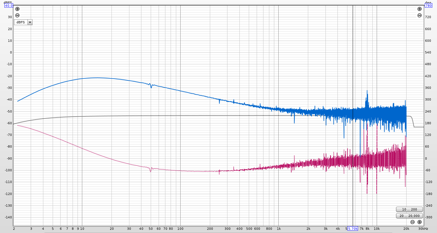
For the power I decided to go USB C PD, 20 v. this gives a lot of headroom for internal voltage. But it introduces some noise. I'm waiting for a LM7815 to limit the voltage but with better noise.. I hope.
Problems encountered while developing:
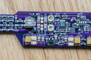
- Breadboard was ok, but some extra noise, so I tried on a protoboard.. but I always messed up something so decided to go PCB. Amazing. I should have done it before. Perfect quality, super low price, and only some waiting.
- Of course first version was wrong. So v1.2 was born... with more care on the lines and the logic.
- USB C PD noise. A lot. Everywhere. I tried to sprinkle a lot of capacitors around, some low pass... Finally the noise level is not bad, but now I'm waiting for a LM7815 that I hope will make it better.
- Maybe I over engineered the idea of two stereo audio lanes, but as the minimal order is 5 PCBs. and adding some more is for free... I have a lot of empty PCBs waiting to be populated.
- The printed case did not account for all the component when the PCB was populated. Finally some pliers made it work. Also I would try a snapping case next time. Although I had to use rubber bands to keep it together but it helps with the grip of the mixer to the table! so happy accident!
Future improvements:
- The idea to have separated input and an output lines was to be able to create a monitoring configuration. Delaying the union of both lines to after an op amp buffer allows to have a separate output for monitoring and another input for monitoring. The monitoring output doe snot mix the input for monitoring, but the final output does. I've seen on some professional mixing desks and it's very useful. Anyway this configuration is not applied in this prototype. This would be the configuration:
Input | Input | Input | Output | Buffer | Input | Output
   |_____|____|_____|_____|________ |> ______|______|
- Maybe add more lanes to allow a button or switch to send individual inputs (or a mix of them) to be sent to an alternative output. This can be useful for recording.
- It would be nice to have another op amp directly at the input to avoid a possible voltage divider with other connected outputs. This already happened to me using a patch bay. Same at output.
- It would be nice to have balanced inputs and outputs.
- Lower power noise. DONE!
- Maybe there is no need for 100k potentiometers. Actually I don't even know what difference does it make. For sure shorter ones, as the ones I got are super long.
- Overdrive indicator.
- Equalization.
- Now it's using USB PD at 20v. Maybe there is some way to do it at 5v with the same...
 Bud Bennett
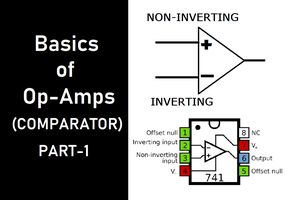
 ElectroBoy
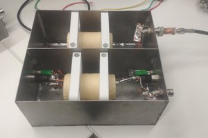
 kevarek
 Ted Yapo