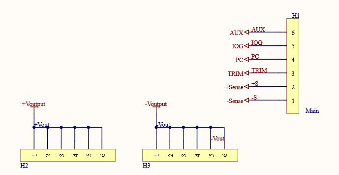
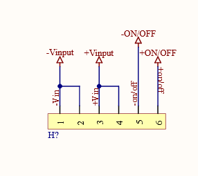
SCHEMATIC DIAGRAM
This section will show the schematic drawings of the boards
FUNCTIONING
A 400V to 5V Cincon Buck converter is selected as the power source for low-voltage electronics. Operating within an input range of 200-425V, it will efficiently step down the car's battery's approximately 380V input to a regulated output of around 12V. This reduced voltage is distributed to the electronics through a Power Distribution Board (PDB).
The Cincon Buck converter integrates a Trim pin for precise adjustment, allowing it to approach the desired 13V2 output. Isolation is achieved through an integrated circuit (IC), eliminating the need for additional precautions in the high voltage (HV) to low voltage (LV) setup.
Due to significant heat generation, effective thermal management is crucial. To dissipate heat, the recommended approach involves utilizing thermal pads and a heat sink.
Safety measures are implemented to protect the converter and connected electronics. An input fuse is employed in series to handle excess current, while a Transient Voltage Suppression (TVS) diode is connected in parallel to safeguard against overvoltage and enhance sensitivity to voltage fluctuations.
To ensure compatibility with standard pinhole sizes, the boards that have been designed will be employed in the system to translate electrical properties from the Cincon Buck converter's unconventional pin diameters. This facilitates seamless integration and enables efficient electrical connectivity with other system components.
We will be using JLC PCB for supplying great PCBs in a timely manner: https://jlcpcb.com/?from=RAT
RESOURCES
For more information on the Cincon Buck:
https://www.cincon.com/productdownload/CFB750-300S-series-application-note.pdf
For more information on the HV Board:
https://docs.google.com/presentation/d/1-DHTeqpuINjpP5vGkZyTaG_ZxEAFXvcwOHXnC1L98Ao/edit
 W4KRL
W4KRL
 Electroniclovers123
 electronicsworkshops
 Kuba Sunderland-Ober