 Alan
AlanSummary
I don't have an oscilloscope at home. I wanted to have the smallest oscilloscope that I can use on a web page! So, I tried making one using Seeed Studio's XIAO-RP2040, which is based on RP2040.
Hardware
Ultra Small Ethernet + RP2040 Board Production Record
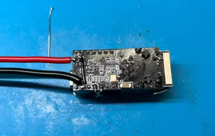
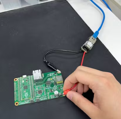
I recently developed a module that combines the XIAO-RP2040 and the Ethernet chip, W5100S.
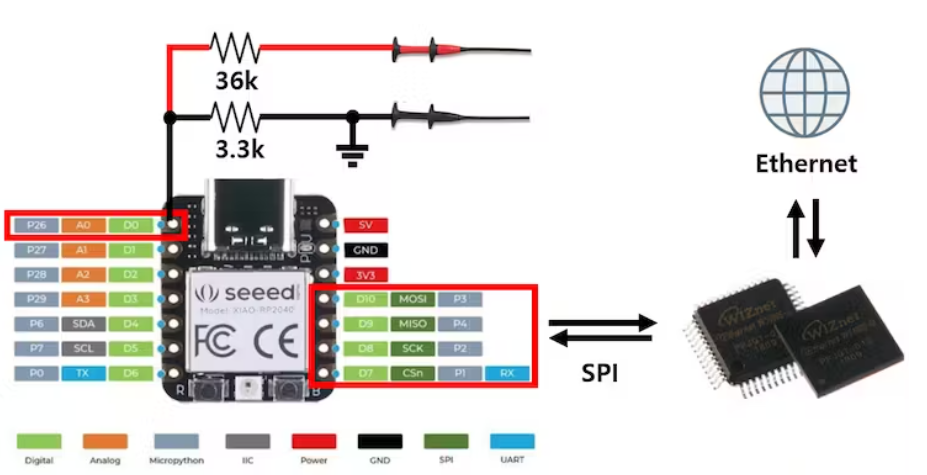
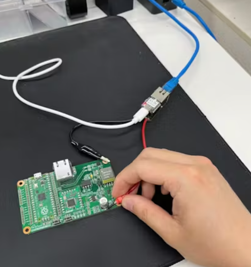
The hardware configuration is as follows: a simple method of using ADC to transmit data over Ethernet.
By simply connecting two resistors and a probe to P26, the setup is complete.
I was a little confused in the resistance calculation.
I want to measure the voltage to the second decimal place.
The Raspberry Pi RP2040 ADC has a resolution of 12 bits. In other words, the value of 0 to 3.3 V can be expressed by dividing it by 4096. I wanted to measure the voltage by 0.01V. < 0.01V * 4096 = 40.96V >. This means that if measured up to about 40V, it can be read in units of 0.01V.
3.3V is the MAX value, so the resistance value is 40B/(A + B) = 3.3.
3.3A = 36.7B
That is, it can be set at the ratio of <A : B = 36.7 : 3.3>. I designed with 36k : 3.3k.
It was fixed with silicone so that the resistance would not fall.
Firmware
It was possible to develop it comfortably using WIZnet's RP2040-only Git.

Change the pins in the corresponding code.
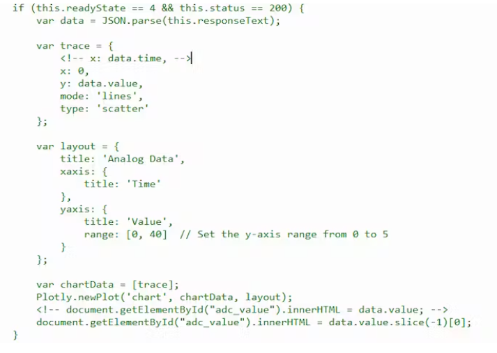
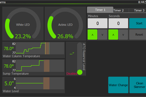
Since it will display a value in HTTP, it is necessary to create an HTML code.
The x-axis is set to time. The y-axis is an analog value and is set to a maximum of 40.I received the data in real time and distributed it. Please check my collar for a detailed code.
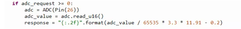
And I calculated the response value and made it. Value to be displayed on the actual web.
The ADC on the RP2040 has a resolution of 12 bits, but the representation is changed to 16 bits. In other words, the value read by adc must be divided by 65535 and multiplied by 3.3V to output the actual input. And the exact resistance I put on is 36k + 3.3k = 39.3k. Therefore, the actual voltage value that can be expressed is 39.3V instead of 40V.
39.3 / 3.3 = 11.90909
So multiply the above by 11.91. Then, when the 3.3V input comes in, the calculated value of 39.3V is output.
(0.2V is the Offset value.)
Test
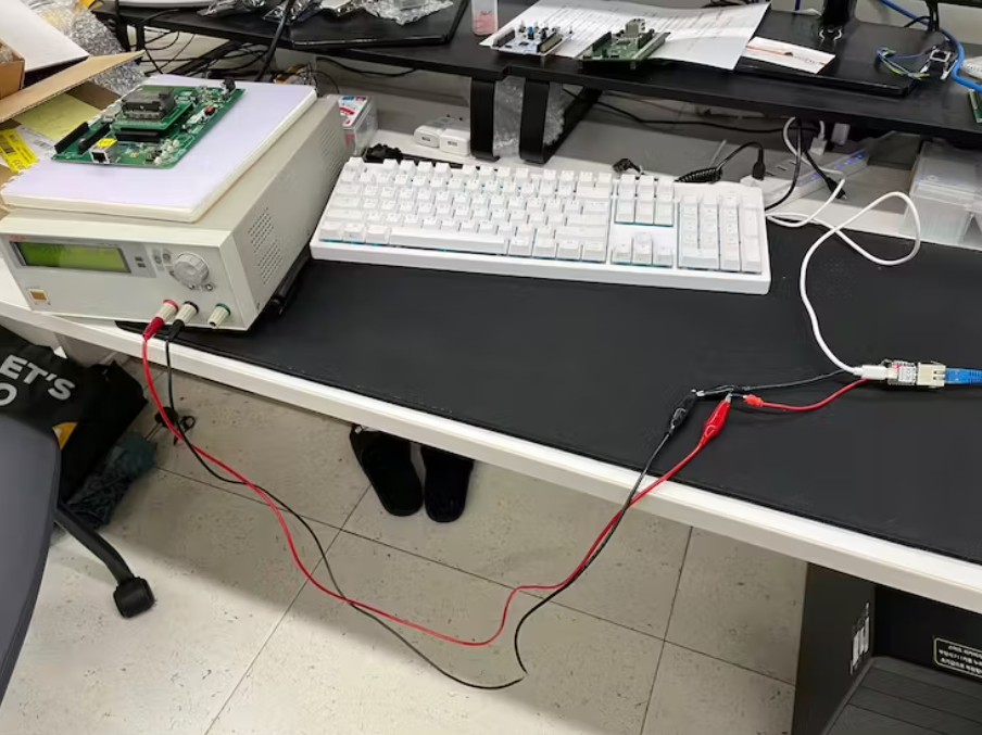
Now it's time to test. Enter power to Power Supply. Unfortunately, the supply I have can only output up to 31.5V.
Here's the motion video!
It works very smoothly and well. The ADC on the RP2040 can be read up to 500 kHz. I haven't experimented with it, but this device probably won't read at 500kHz due to multiple delays, but it will read at a rate comparable to that.
You'll be able to check various boards like this. The power line is so annoying that I'm going to make a PoE module next time.

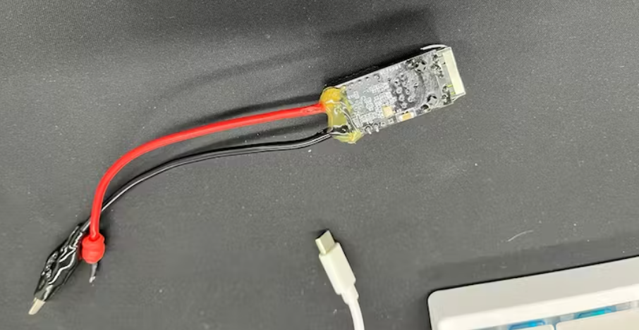
The design is already in its final stages. It looks a little big, but it will be made much smaller than you think.
When the board is finished, you'll be able to do anything very compact like this.
In a very, very small form!
End
There are many scopes, but there will be no such small and efficient scope! Make it very, very simple! It's so comfortable!
 Skyler Brandt
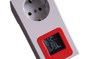
 Sebastian
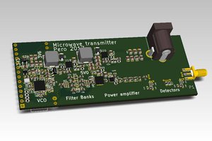
 Pero
Pero
 Aleksa
Wouldn't it be hard to measure the current?