 Skyler Brandt
HMI and Main Controller
The main controller consists of Raspberry Pi and a 7" touchscreen.
WiFi
There's several reasons I want to have this thing connect to the internet, but mainly I want to be able to control my AquaPic from anywhere with my phone.
Power Supply and Communication Bus Connectors
I plan on using a power supply for the 5Vdc and 12Vdc. The different slave modules will be mounted to a DIN rail. RS485 will be used for serial communication.
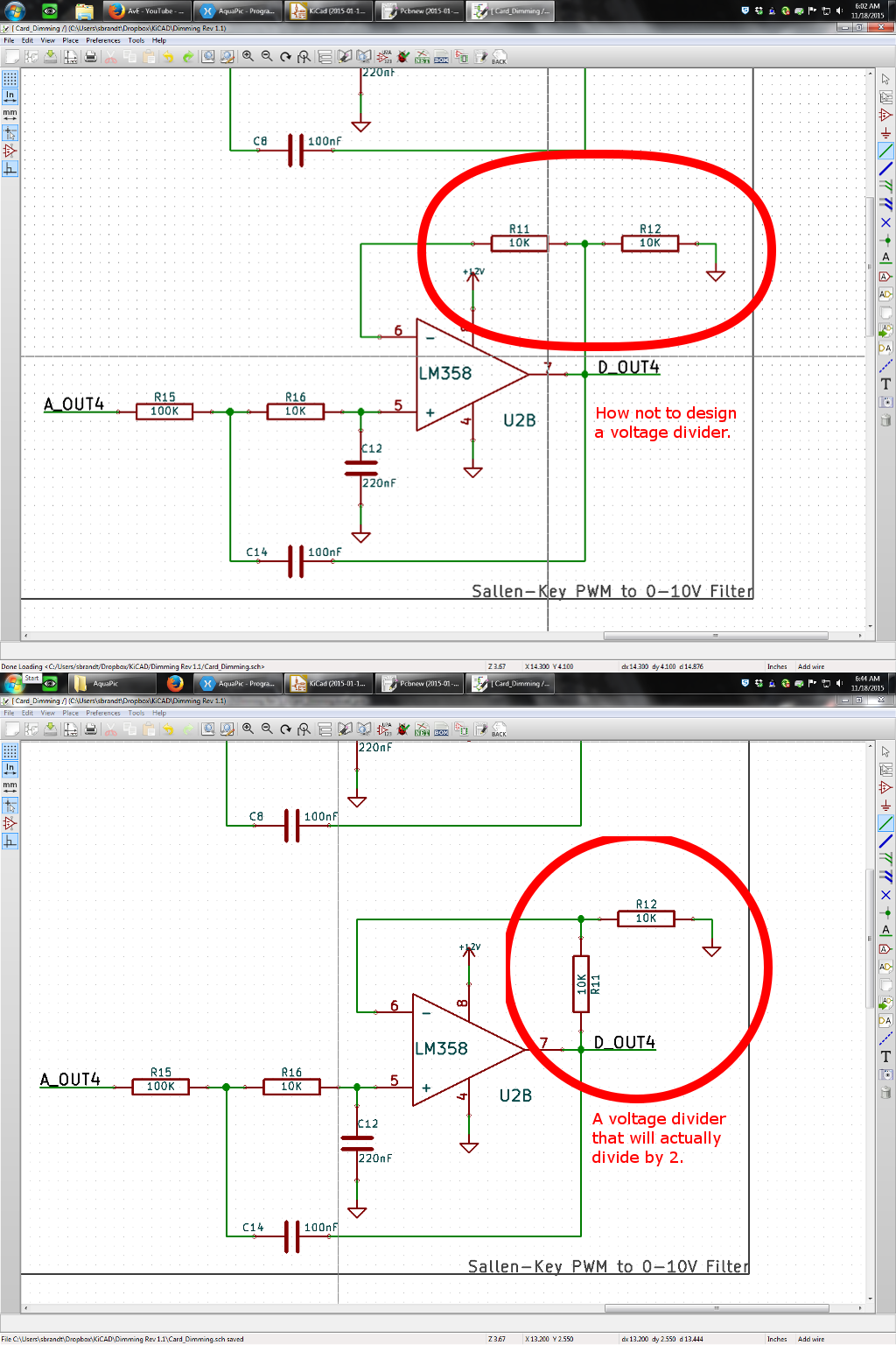
4-Channel 0-10V or PWM Dimming
The AquaPic will include both PWM and 0-10V dimming references for lighting. To accomplish this I'm using a micro to generate the PWM signals and then programmable switching that straight out or through a filter/gain circuit for 0-10V.
6-Channel Input
General inputs used for float switches, flood detection, button, etc. The front on the input card will have blue LEDs to indicate which switch is closed.
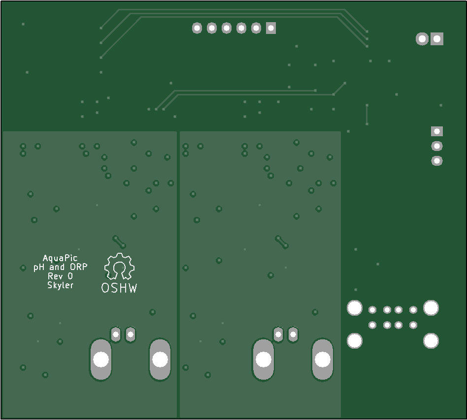
pH and ORP Input, Gain and Isolation
This card will incorporate two galvatically isolated circuits for pH and ORP measurement. The first input will only measure pH and the second will measure pH or ORP.
Temperature and Level Monitoring
I will be using both temperature and level sensors that output linear voltage, between 0-5Vdc. This way I can plug either a temperature sensor or a level sensor into any of the 4 channels this card will have.
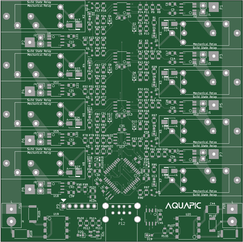
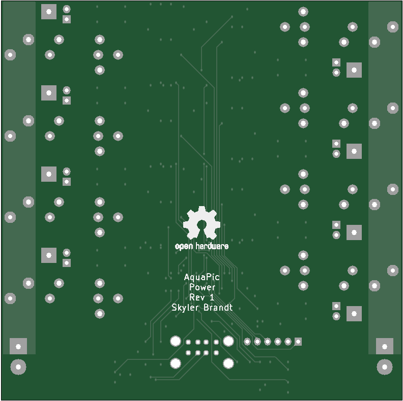
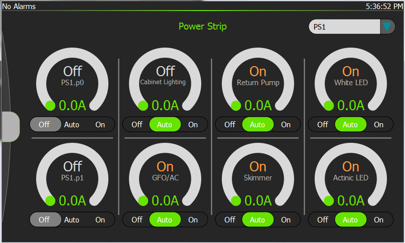
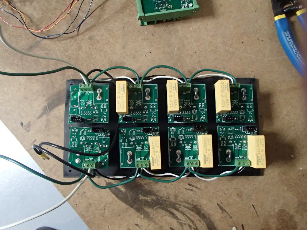
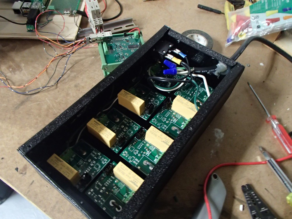
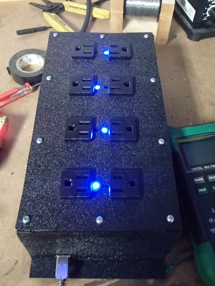
Power Strips
Each power strip will include 8 outlets controlled by either a solid state or mechanical relay. I would also like to measure the current on each of the outlets.
Please visit my build log website for more information.

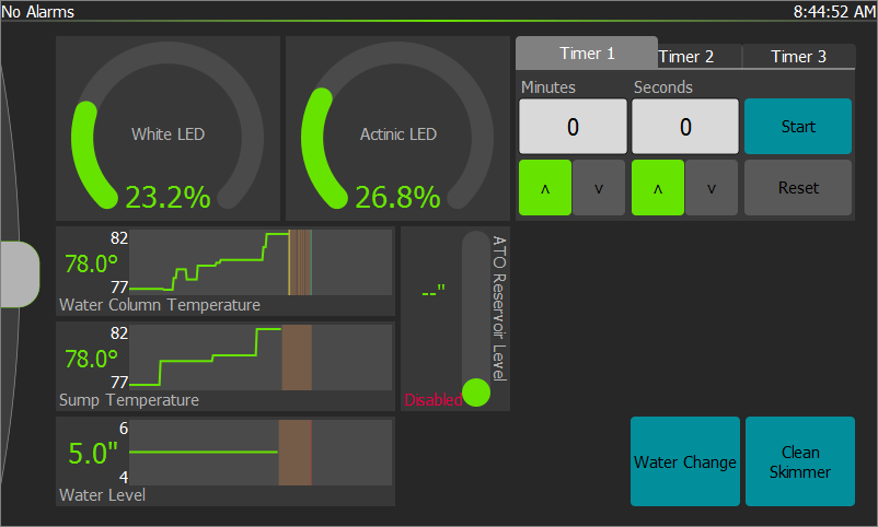
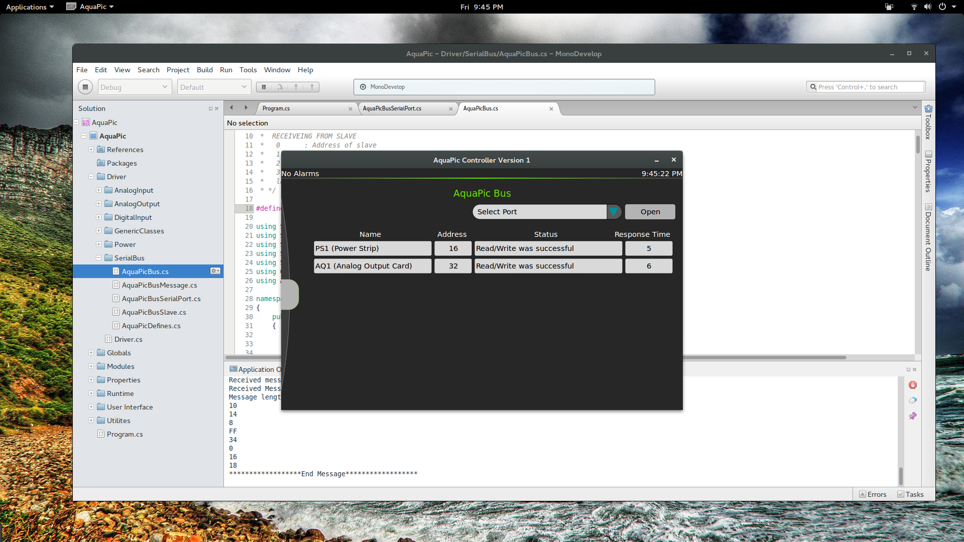
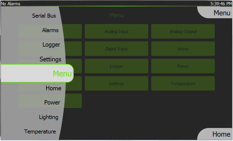
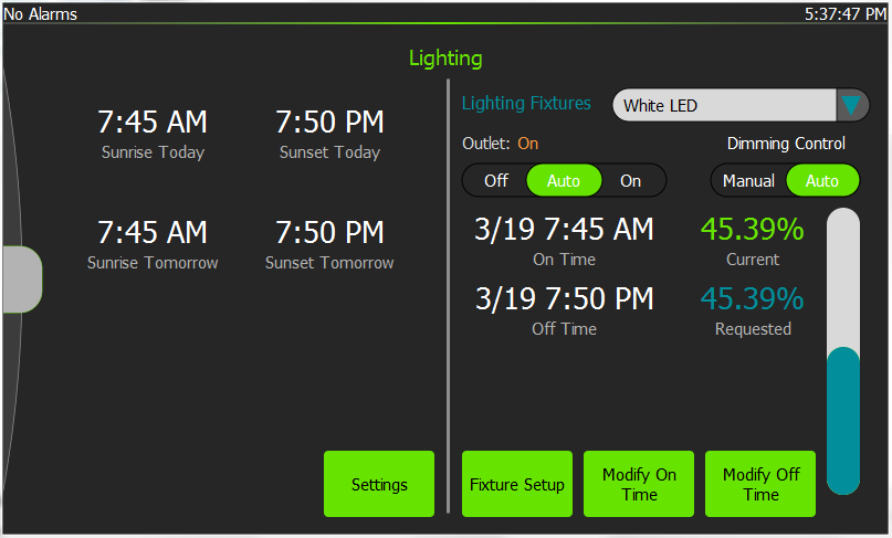
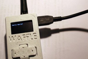
 I've been making good use of my free time though by making the user interface pretty.
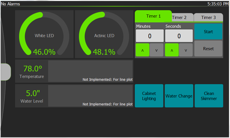
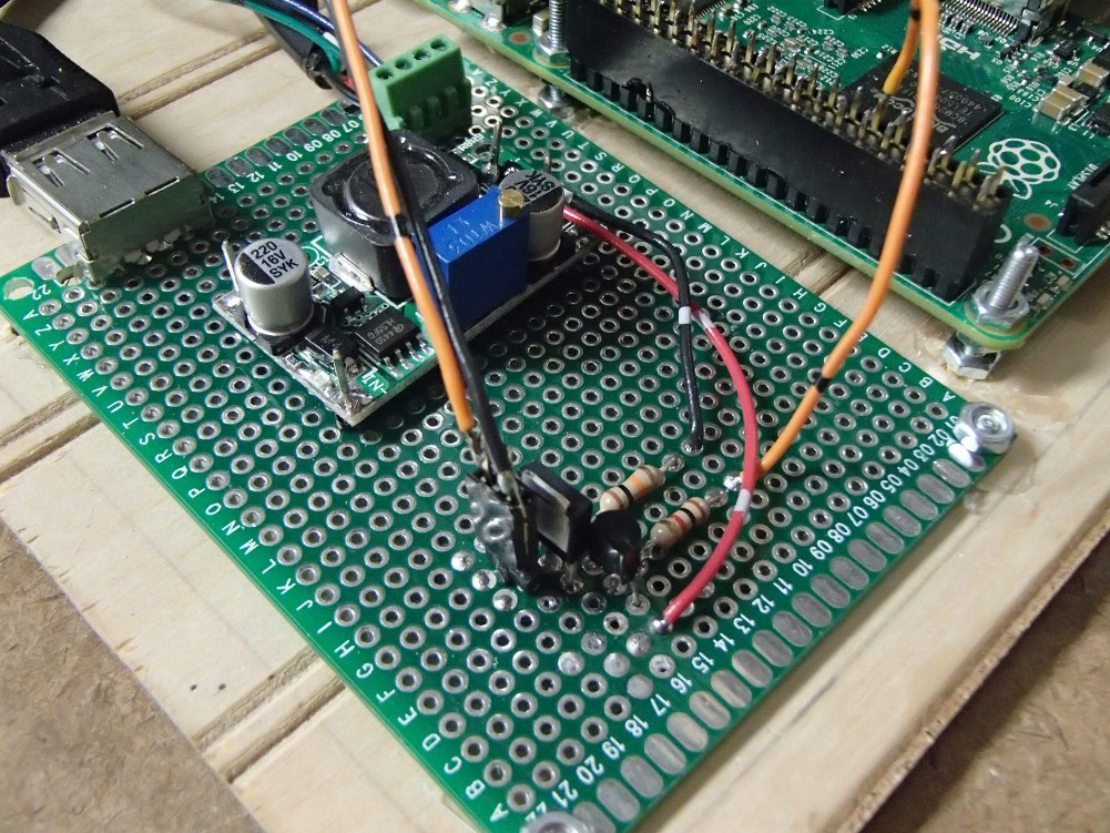 The little boost DC-DC converter fixed all my low voltage issues for the RPi and touchscreen. I was surprised that was such an easy fix. Getting a MOSFET paralleled with the backlight controls on the touchscreen was not and turned out to be a bit more involved than I expected. Most of the difficulty was self induced though. The best solution I could come up with for bodging a SMD SOT-23 was three pads on a SOIC breakout board. It was ugly but it probably would have worked. However, problems arose when I referenced the MOSFET and driver circuit off neutral of the power supply I would normally use but then powered the RPi from a different power source. I didn't catch my mistake at first, and instead concluded that my bastardized SMD work was the culprit. So I ordered a proper through-hole FET and once again it didn't work. That was when I finally realized my mistake, switched my power to the correctly referenced source, and everything worked as expected. Now when the screensaver come on, the backlight turns off and then when I touch the screen the screensaver goes off and the backlight switches on. I designed the gate circuit a little different than most other p-channel gate control. The gate is normally connected to ground though a resistor. Then a transistor is placed on the high side to pull the gate up and shut the MOSFET off. That way while the RPi is booting or something happens to the script that controls the GPIO, the backlight will fail on.


 M.daSilva
 The Big One
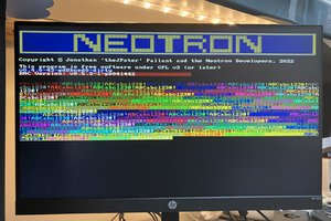
 Jonathan 'theJPster' Pallant
Hi
Nice to meet you after viewing your profile i am Jacinda, from (jakarta) indonesia,
i have a project discussion with you please email me on: (jacinda.seiler@yahoo.com)