 Dan (a8ksh4)
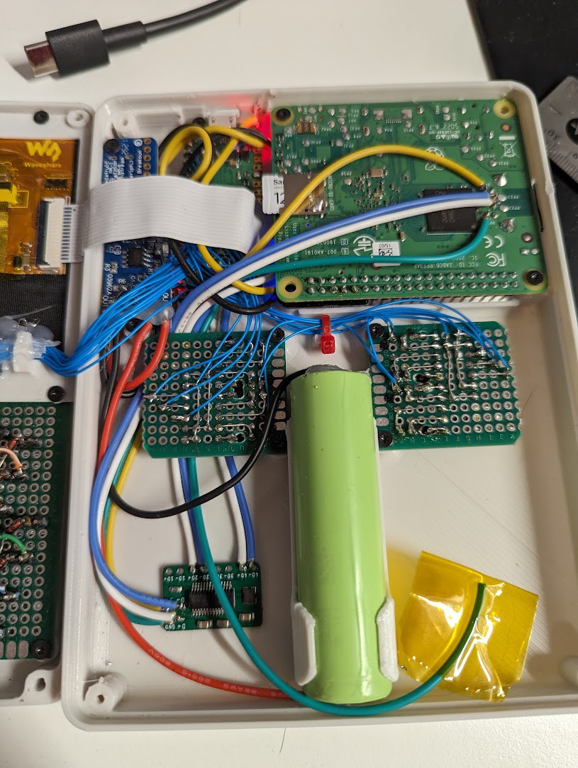
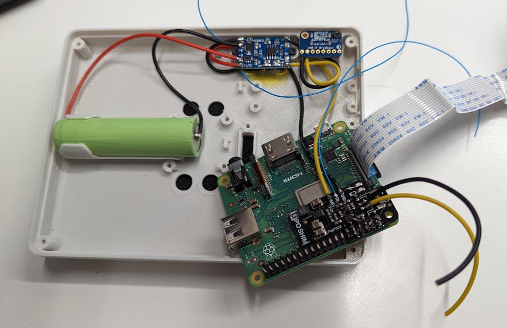
Power System:
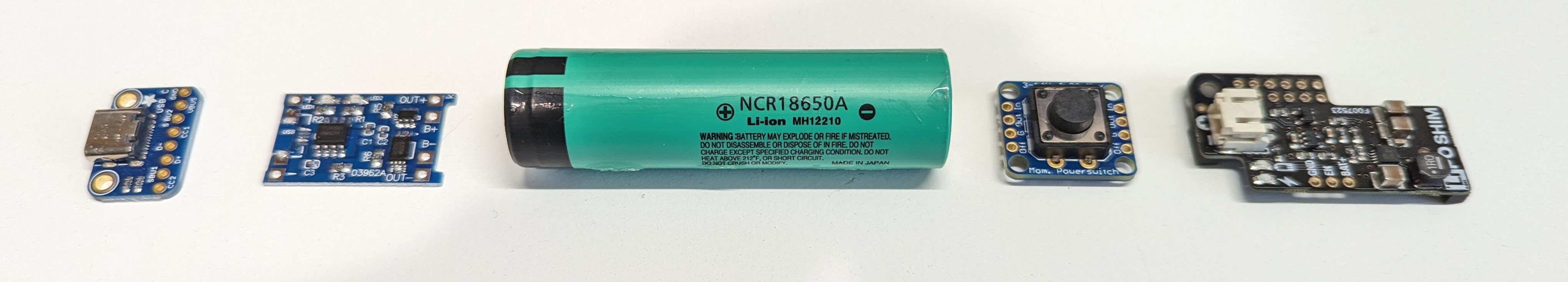
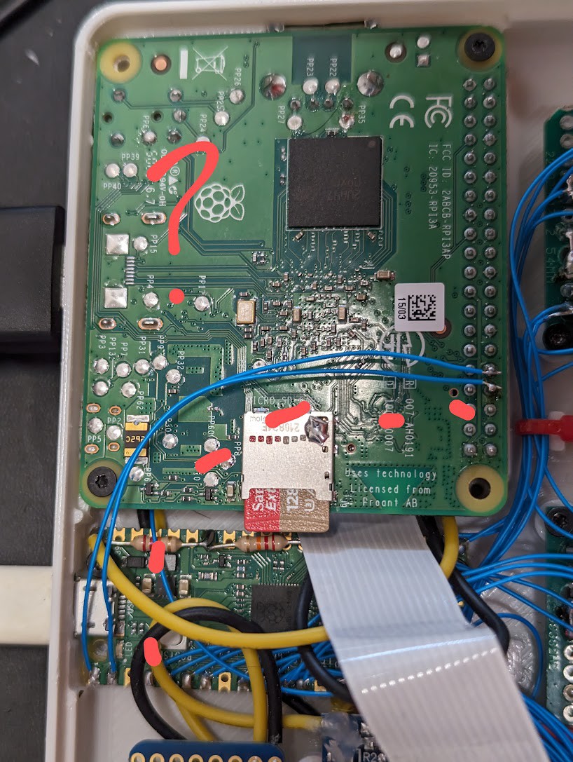
- The battery+ is connected to one of the analog pins of the Pi Pico via resistor bridge (to reduce voltage by 1/2) to monitoring and reporting to the Pi 3.
- The LiPo Shim has an enable pin, but it's pulled high and requires some additional external circuitry to enable controlling it by the Pico. To simplify things, the Adafruit Momentary Switch is used. Push the button for hard on/off, and the pico can shut off power by switching it's "off" pin high.
- Between the Pico firmware and the service on the Pi, low battery can trigger warnings (e.g. screen brightness flicker), clean shutdown, and complete power off.
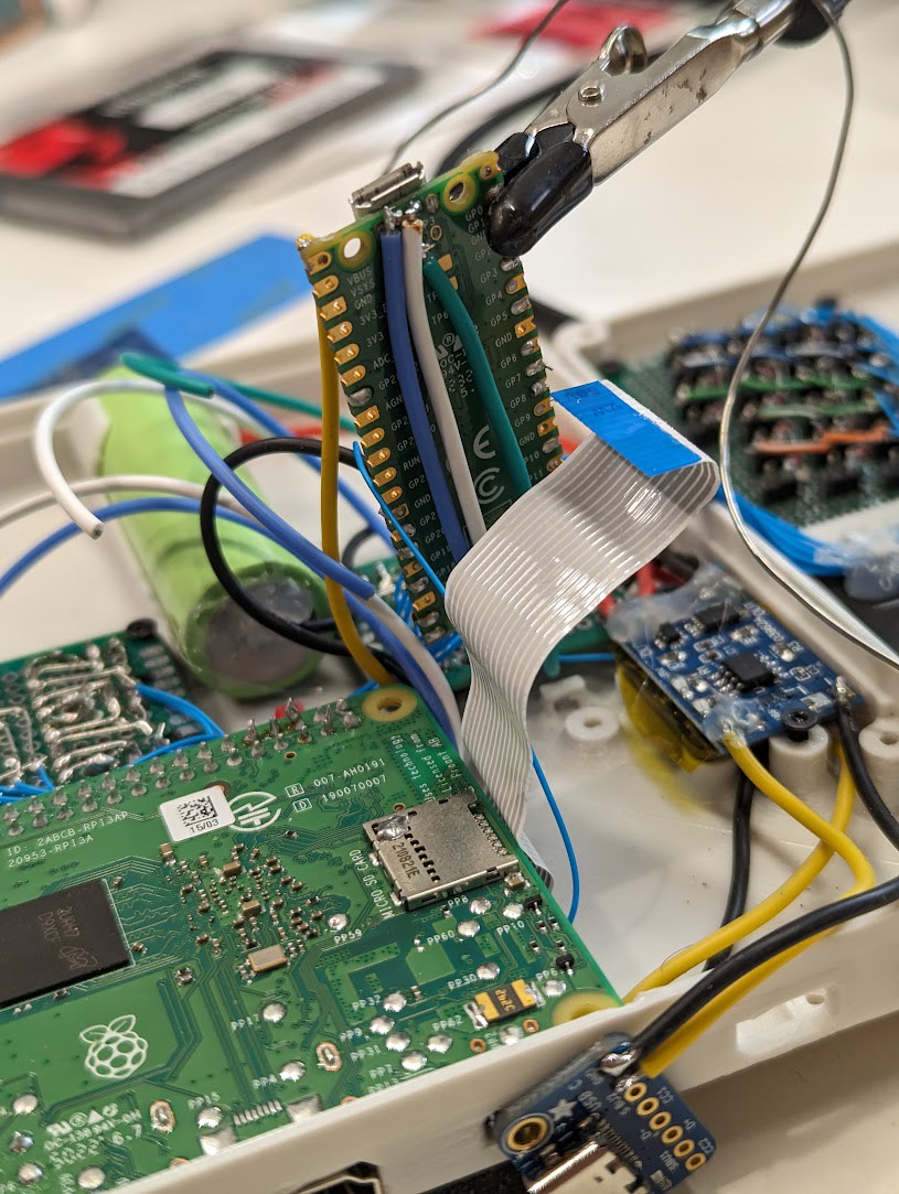
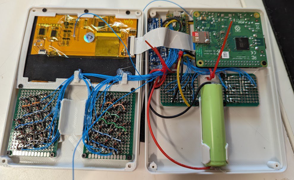
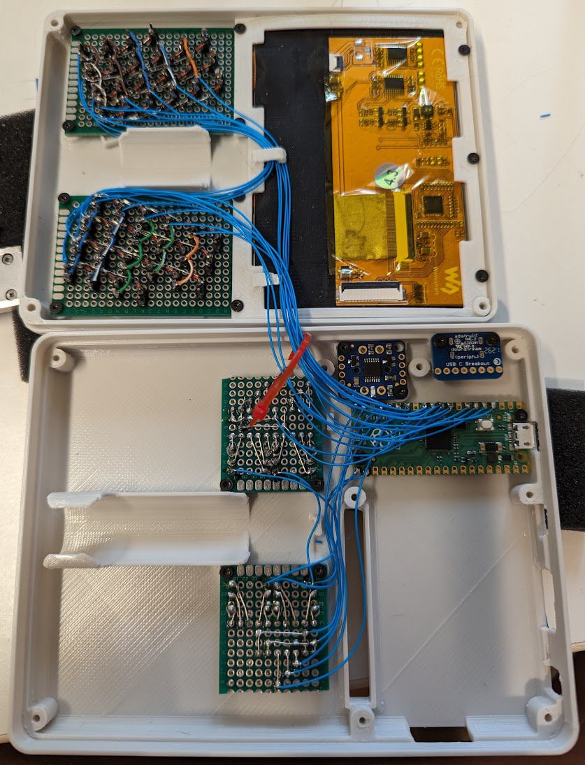
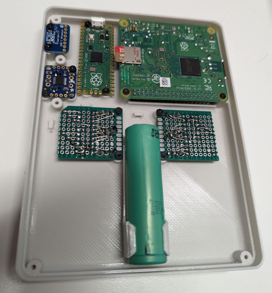
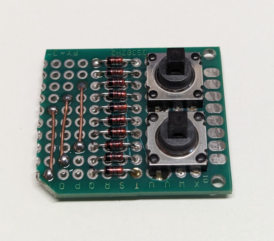
Pi Pico Wiring:
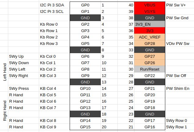 The Pico is sort of the brains of the whole operation. It handles all the user input and manages power. Summary of functionality:
- Reads the front keyboard and rear 5-way switches
- Uses an analog pin with a couple voltage dividing resistors to read the battery voltage from the VBUS pin
- Uses GPIO22 for complete system poweroff
- Uses GPIO21 to toggle power to the Pi 3 shim
- Uses GPIO0, GPIO1 as SDA/SCL for sending keyboard and power info to the PI 3


 Taylor Hay
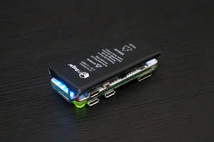
 Jdaie
Jdaie
 sotasystems
 Jacob Daniels