J Gleyzes
-
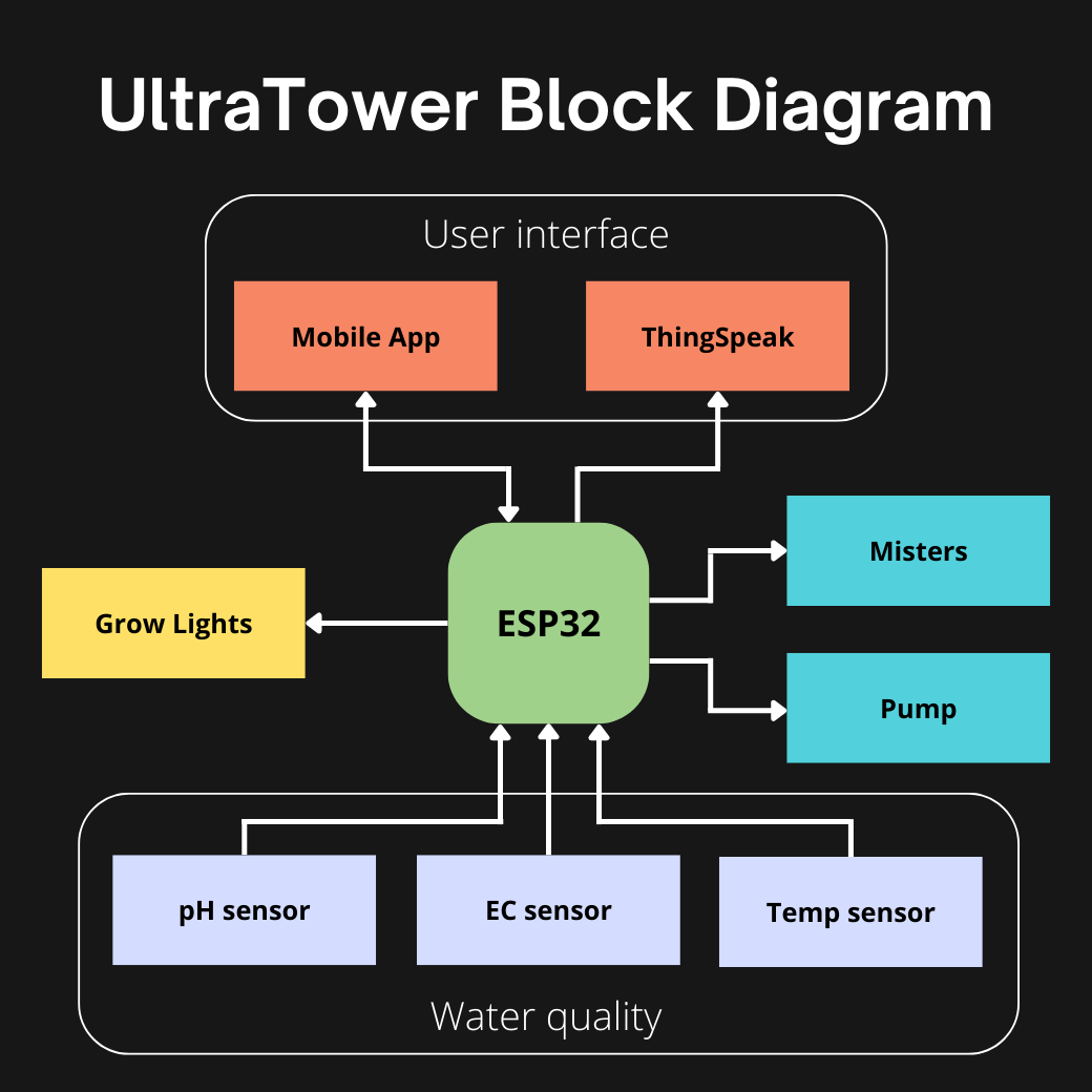
Functional block diagram
07/04/2023 at 05:13 • 0 comments![]()
Microcontroller:
The chosen microcontroller is an ESP32 because:
- The high frequency generation is simple
- Bluetooth and WiFi (to communicate with a phone or send data over the internet)
- Low power consumption
- Capacitive touch GPIO (water level sensors)
- Lots of pins for the many sensors
The ESP32 MCU is the heart of the system. It manages (or will manage) all the following functions.
Misters:
For the moment I am focusing on the optimisation of the most important block which is the misters. It is the activation of the disks at 108kHz that allows to create the fog composed of water and nutrients. As this log shows it's going pretty well.
Pump:
The pump is a finished block, it allows the water to flow back into the small tank when the water level is low. Because the disks should not work without water, it damages them.
Water quality:
These are the next blocks I need to work on. They consist of a pH sensor, an EC sensor and temperature sensors (in the main tank, root chamber and ambient temperature). The water quality is very important, for the plants to grow optimally.
User interface
Once the sensors are implemented, adding thinkspeak will be quite simple to see datas in real time. In the future, I'd like to make a Kotlin application to be able to receive data from the sensors but also to change the tower parameters (misters activation time, target pH, temperature alert, ...)
Light Grow
The addition of horticultural LEDs will allow plants to be grown anywhere, even in a cellar. But not necessary for sunny gardens or balconies.
A lot of work!!
-
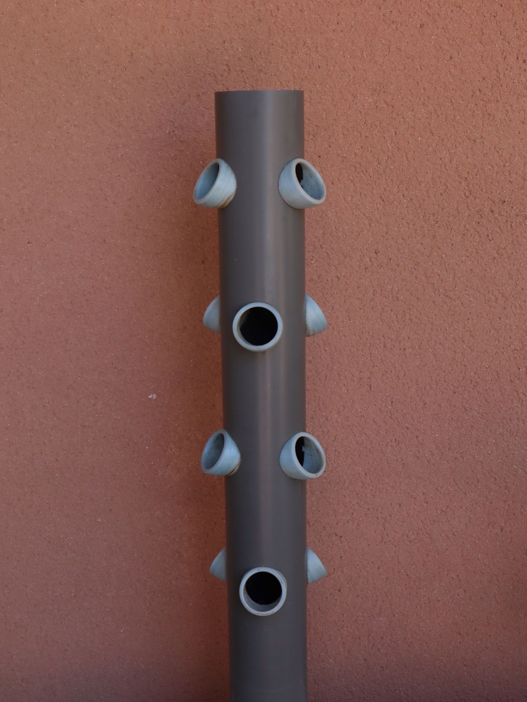
Improvement of tower PVC pipe
07/04/2023 at 05:12 • 1 commentThe PVC pipe is an important part of this system. It is 100mm in diameter and 1 meter long, allowing 12 plants to be grown on a very small footprint.
Using the height allows us to optimise the number of feet per square meter.
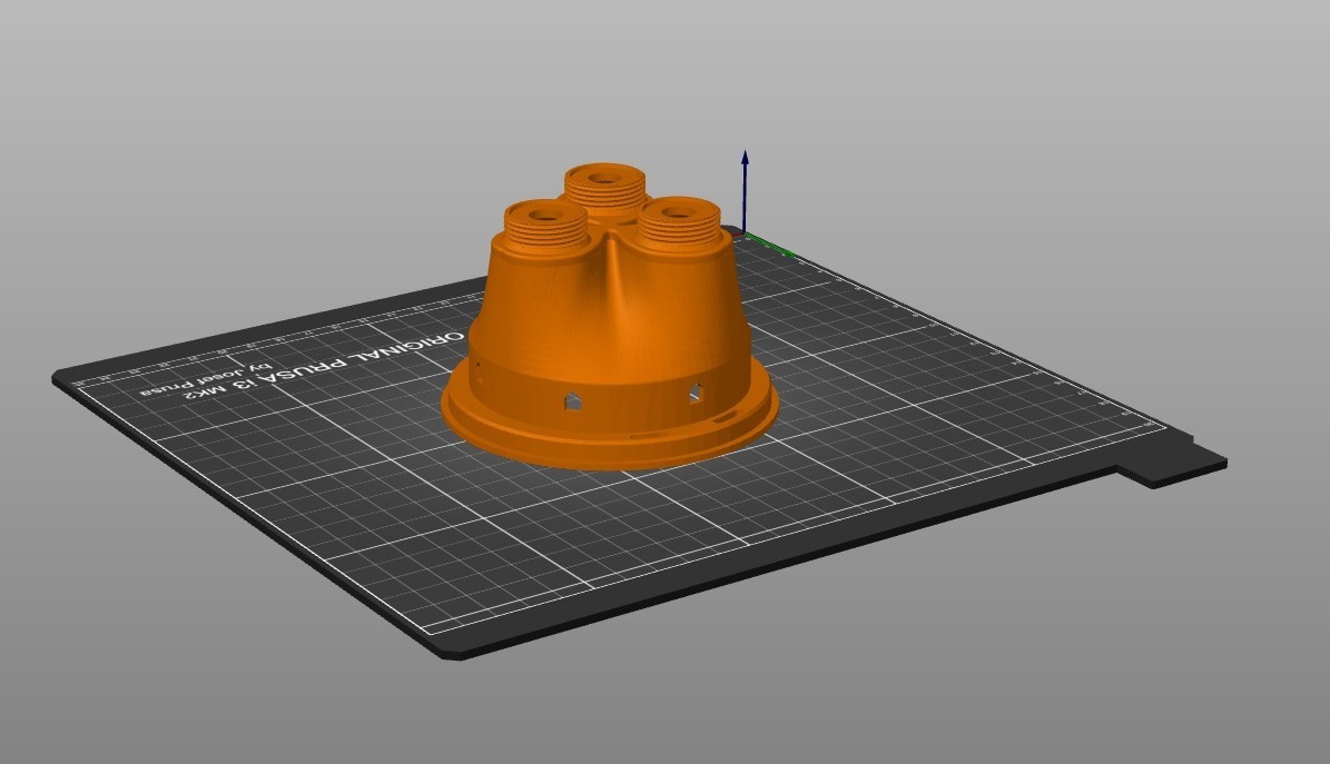
This PVC pipe is essential for this project however the current PVC design can be improved.Current design :
![]()
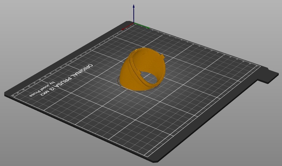
For each plant, this part must be printed.
![]()
It takes more than 1.5 hours of printing per piece, which makes 18 hours of printing for one tower. A lot of energy and plastic wasted.
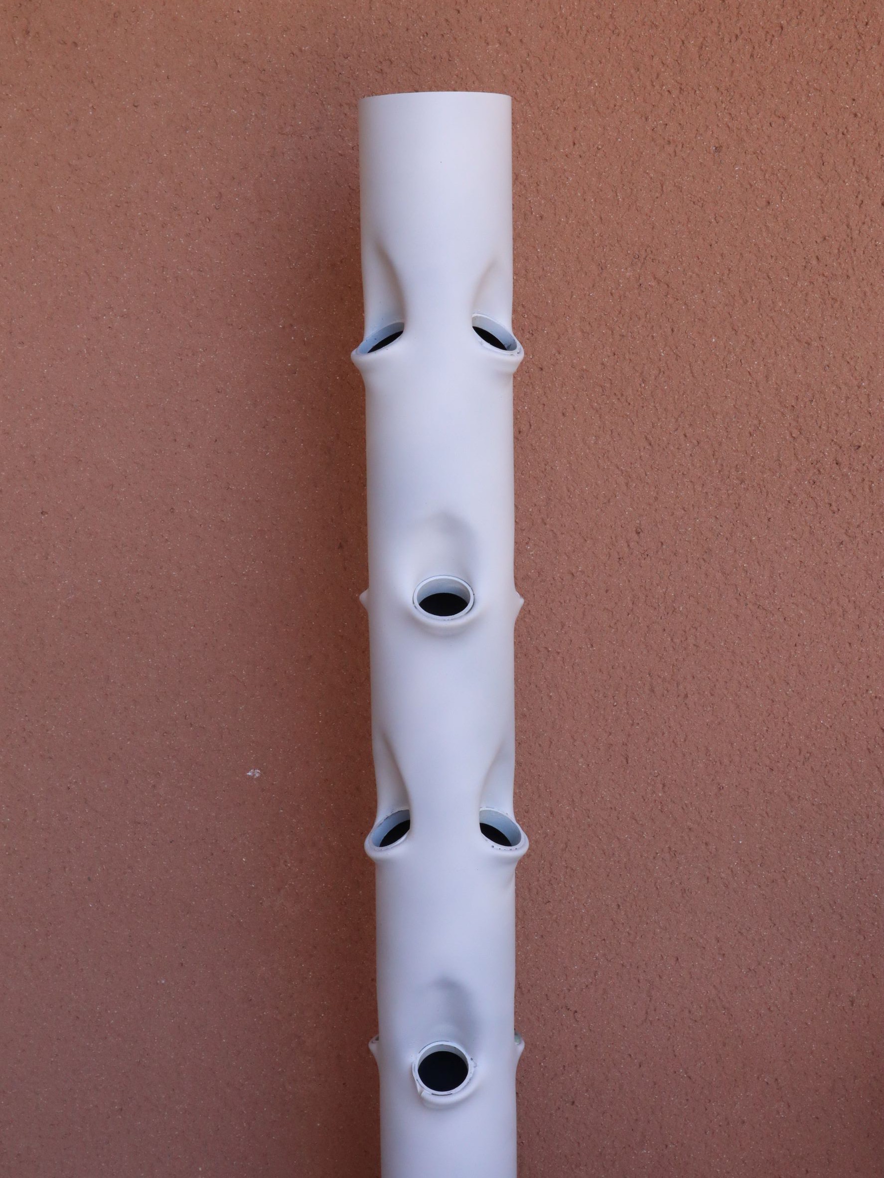
Moreover this part gives a little too much horizontal angulation to the plants.New design
![]()
PVC can be heated to make it take a particular shape. The idea comes from this youtube video.
I thermoformed the large PVC tube with a small 40mm diameter PVC pipe which allows me to cut small 1cm long sections and glue them inside to make a small rim for the baskets.
![]()
When I have some time I'll make a video of how to do it.
I then painted the PVC white to reduce the heat inside the tube on sunny days. -
MOSFETs are finally cold !
07/04/2023 at 05:11 • 0 commentsWhen the disks were activated at a frequency of 108 kHz the MOSFETs slowly increased in temperature. The trick is to put 3 of them and to alternate their activations to allow a cooling.
It was necessary to find a solution, because the generation of heat is a waste of energy and moreover I cannot put the disks in continuous activation.
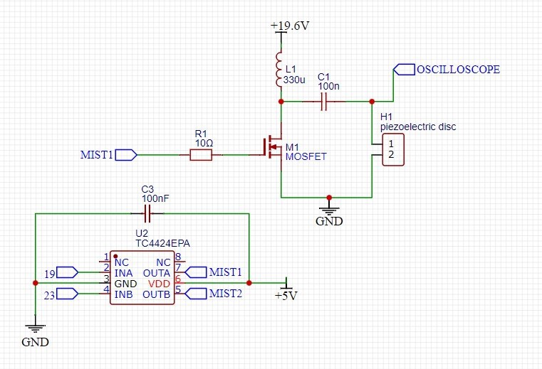
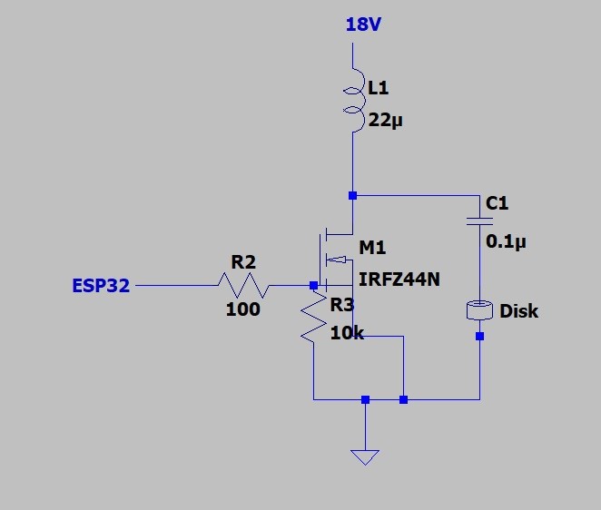
We need to get out the oscilloscope to understand.Here is the circuit used:
![]()
The only component tested in this log is the MOSFET M1.
The oscilloscope is between the capacitor and the disk.
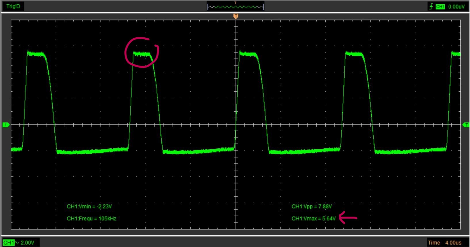
With the IRFZ44N MOSFET:
![]()
We observe that a plateau is created at 56V, which is responsible for the creation of heat as lowering the source voltage from 19.6V to 16V the plateau disappears, the MOSFET is cold but the power of the disk decreases.
In the LTSpice simulation with this choice of coil and capacitor there should be no plateau. But this 56V plateau corresponds to the Drain-to-Source Breakdown Voltage of the IRFZ44N.
It is necessary to change MOSFET and to take a higher Drain-to-Source Breakdown Voltage.I searched in my stocks and had some P5515BDs left (with Drain-to-Source Breakdown Voltage of 150V)
Perfect for testing.
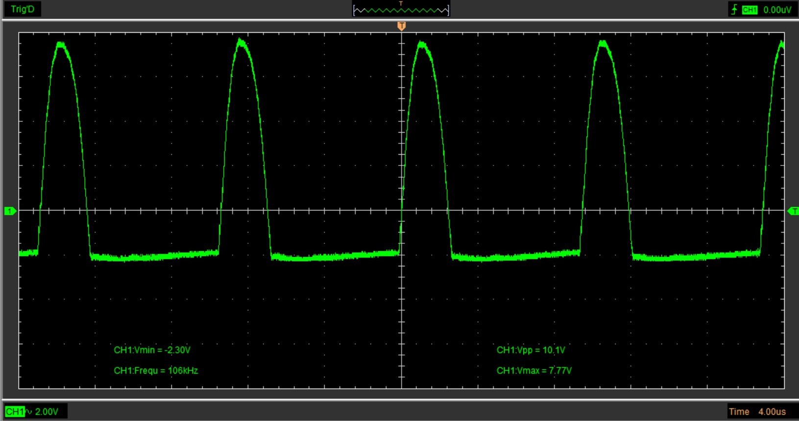
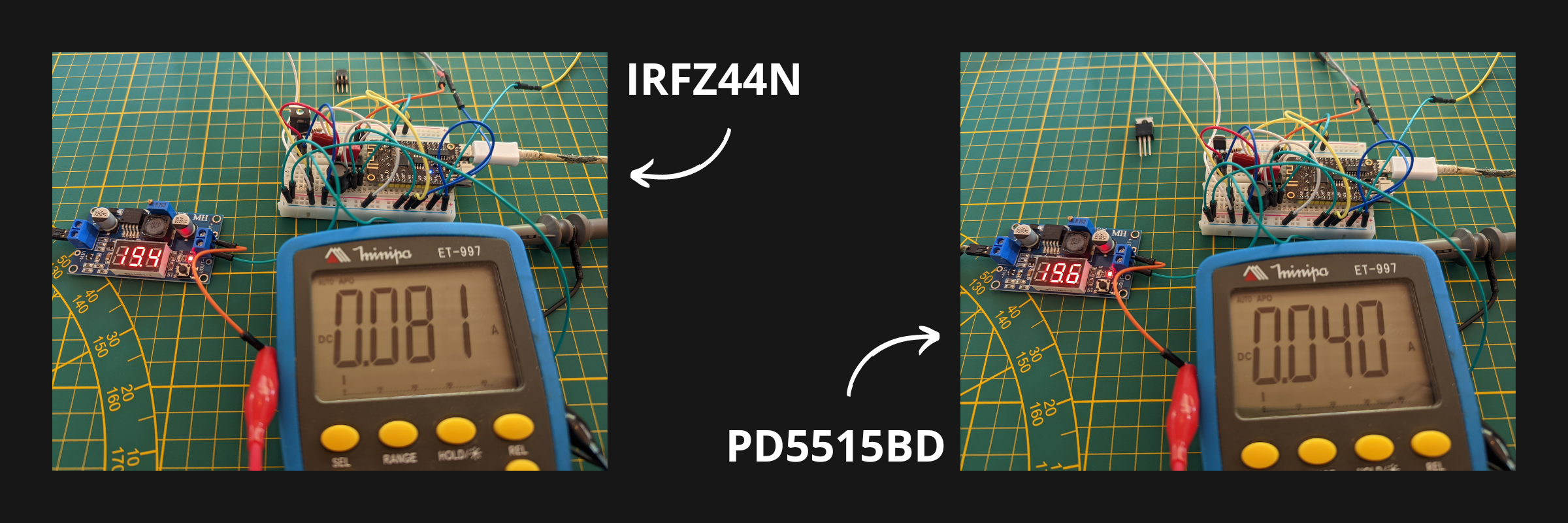
With the PD5515BD MOSFET:
![]()
There is no more plateau and Vmax reaches 77V, the coil and capacitor are working at their full capacity, they are not limited by the MOSFET anymore.
Energy efficiency
![]()
As we can see with a well dimensioned MOSFET the consumption is divided by 2!
Small victory of the day!Summary
The MOSFETs do not heat up at all (for the 108 kHz frequency), and we can use them continuously.
The power of the disks has increased, they create more fog with a power consumption divided by 2!
For the final version of the project I think to use the PD530N15N3 G MOSFET from Infineon.For the moment I will test this version with the P5515BD on a home made PCB.
-
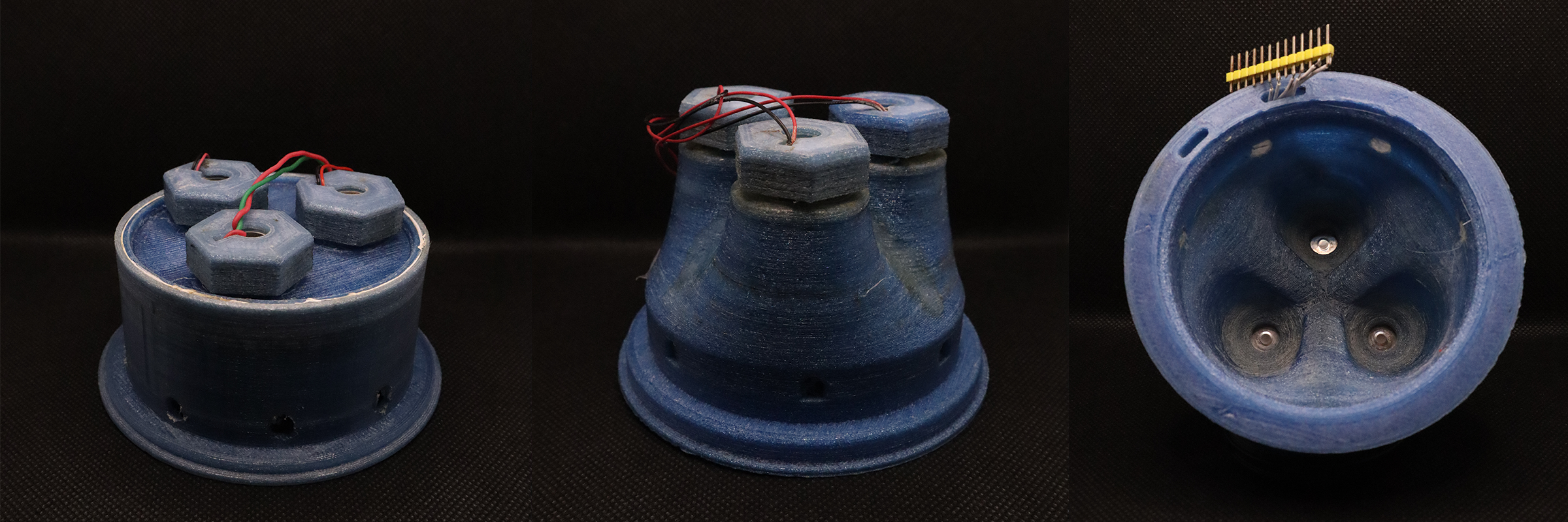
Improvement of the small tank
07/04/2023 at 05:09 • 0 commentsYesterday I put the link to the Thingiverse project to be able to download the STLs but since then there have been improvements on the small tank.
Before it was in 2 parts that had to be screwed together which could lead to a lack of watertightness. For the tests this was not very important as the water falls back into the bottom tank. Due to energy consumption it is better that the water pumped in the small tank stays in it.
The drain holes have been enlarged and the hole for the pump hole moved up to avoid suction when the pump is stopped.
In addition, the one-piece print is a time-saver.
![]()
Version 1 on the left and the new version in the middle and on the right First Version:
![]()
Second version:
![]()
The new STL can be found in the files of this project under the name: small_tank_V2
All the 3D printed parts are made with recycled PET bottle filament (more information in this project of my father)
-
GitHub ESP32 code and STL
07/04/2023 at 05:08 • 0 commentsYou can find the code for esp32 in this Github.
You can download the STLs files on Thingiverse.
The small tank at the top of the tower is composed of several parts that must be assembled as we can see in this video :
The tank is filled every hour by a small 5V pump immersed in the bottom tank.
The small notches allow that the water does not overflow, it falls in the bottom tank, thus protecting the electronics which is normally located just above the small tank.
In the code, you will see that the misters work one after the other allowing a cooling of the MOSFETs.
You can see in the video the little bubbles above the misters when they are activated.
-
The 1.7 MHz disk problem
07/04/2023 at 05:07 • 0 commentsI've been wanting to build an ultraponic system for a few years now.
My very first system was just a bucket of water, the lid was pierced to accommodate 4 plants and a mister floated into the water to create mist. Sorry I no longer have pictures.
I simply bought a ready to use mist maker. You just have to plug a 24V DC power supply and immerse it in enough water to make it work.
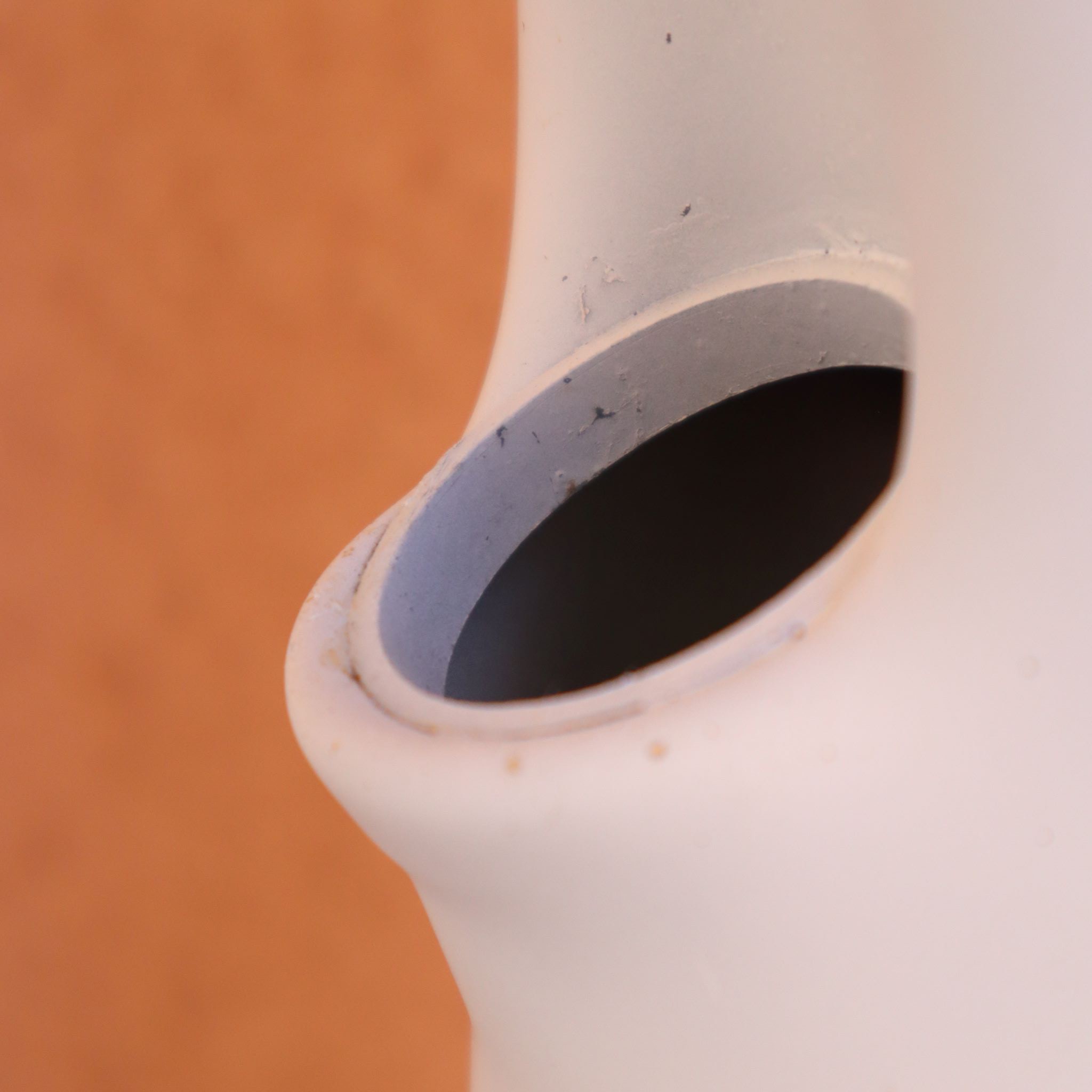
The mist maker contains the electronics needed to vibrate the disk. The electronics is embedded into resin to make it waterproof and uses the water for cooling (clever).![]()
But it heated up the water and was too big for my project! I had to figure out how to remove the electronics from water to avoid temperature rise.
The ready to use mist maker uses a Colpitts oscillator which activates a transistor, you can find the schematics easily on internet.
As I used an ESP32, I prefered to use a MOSFET.The first electronics circuit :
![]()
I turned it on ! And nothing ...
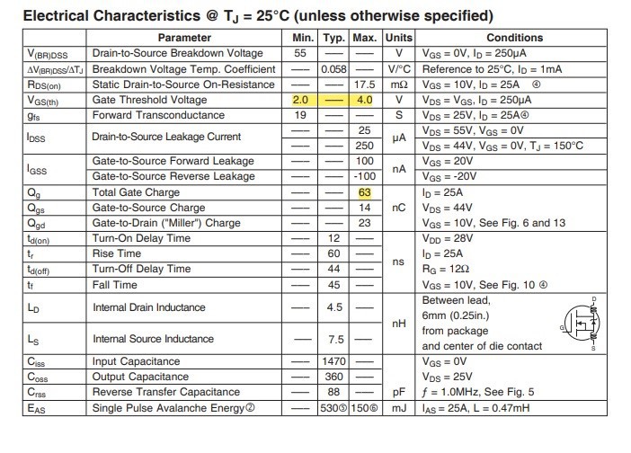
The MOSFET did not switch fast enough. Let's take the IRFZ44N datasheet to understand my mistakes.
![]()
At lower frequencies this circuit works (it's the circuit for the 110 kHz disk just the coil and the frequency change), but at 1.7 MHz we need to turn on the MOSFET as fast as possible.
The ESP32 can deliver 3.3V through its pins but we need a voltage above the Gate ThresHold Voltage of the IRFZ44N which is between 2.0V and 4.0V.
Now to have a good switching speed we need to charge and discharge the gate as fast as possible.- Dt = dQ /i_gate
In my first circuit this gives us :
- Dt = 63 nC / 0.033A = 1909 ns
So we have a possible switching frequency of 0.26 MHz. Far away from the 1.7MHz..
If we now take a voltage of 5V with a gate resistance of 10 Ohm :
- Dt = 63 nC / 0.5 A= 126 ns
The possible switching frequency is now 3.9 MHz
This is perfect but the ESP32 can't handle the 0.5 A current, we need a mosfet driver.
I chose the Microchip's TC4424 driver.Here is the schematics:
![]()
I turned it on! It worked!
However, the MOSFET heats up quite quickly, it needs a fairly large heat sink to allow continuous operations.
And even though I removed electronics from water, it still heats up to 40°C, which is explained by the vibrations of the disk and the small volume of water.
I have learned a lot from this 1.7 MHz disk but I can't use it because water temperature has to be between 18 and 25 °C for hydroponics systems.I am not an electronic expert so it is possible that there is a better way to vibrate this 1.7 MHz disk. Also one could imagine using this kind of disk in colder countries than mine where water may require to be warmed a little.
ESP32 code to generate the PWM at 1.7 MHz is fairly straigthforward:
#define MIST1_PIN 19


// setting PWM properties
const int freq = 1700000; //IMPORTANT
const int ledChannel = 0;
const int resolution = 1; //IMPORTANT
const int dutyCycle = 1; //IMPORTANT


void setup() {

  // configure LED PWM functionalitites
  ledcSetup(ledChannel, freq, resolution);

  // attach the channel to the GPIO to be controlled
  ledcAttachPin(MIST1_PIN, ledChannel);

  ledcWrite(ledChannel, dutyCycle);
}