 Paul McClay
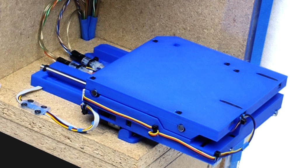
At this time, this log page describes printable parts for the XY stage. Z axis and other accessory stuff to follow Real Soon Now. STLs today; I intend to share the CAD later after a think about how much clean-up it will get.
My 3d printing experience is narrow. PrusaSlicer 2.5.2 defaults for Ender 3 Pro w/0.4 mm nozzle define my normal for whatever I don't mention below.
<update>added PrusaSlicer version 2.5.2 because I just tried 2.6.1. While it looks smarter about bridging over infill under top layers and wall thickening, 2.6 apparently just generally fails at bridges over voids - has since alpha. Bummer.</update>
Briefly:
General
- if PrusaSlicer, then 2.5.2 not 2.6.n -- at least not until bridging gets fixed
- download minamil3dp-XY-STLs-v0.9.1.zip from Files section
- filenames: "minamil3dp-{part}-v0.9.[01].stl"
- Classic perimeter generator
- 0.2 mm layer height
- 0.45 mm shell thickness
- default changed from 0.45 to 0.44 mm at some point; I deferred thinking and changed it back to 0.45
- one perimeter
- fill gaps off
- detect thin walls off
- 10% gyroid infill
- check slicer output for sane bridging angles where crossing over voids
- PrusaSlicer sometimes fails sanity
- bridge from solid to solid -- no turns in free space
- bridge across long narrow voids -- not lengthwise
- fix fails e.g. by setting "bridging angle" in a heightrange modifier
- assuming I've successfully modeled bridgeable details...
- other hardware
- These STLs reflect conservative changes, presumably improvements, since the last versions that I've actually in fact printed for myself as of writing this.
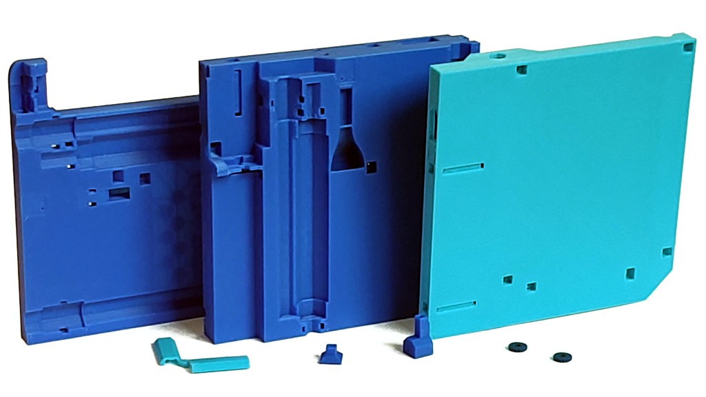
Big parts
- XYbottom - "General" parameters
- XYmiddle - "General parameters
- XYtop - "General parameters, and:
- slice/print upside down
- optional to make stiffer:
- break into parts (not objects)
- inner part set perimeters=11 (whatever gets the slicer's attention) to generate internal structure
- I haven't assessed the practical benefit beyond making the part qualitatively less bendy
Small parts
- XYwireguide
- two perimeters
- XYtietoolshort, XYtietooldeep
- two tools; print one of each
- slice/print big end down
- fill gaps on
- 100% rectilinear infill
- XYbladj
- print two parts
- slice/print flat side flat
- Arachne perimeter generator
- 9 perimeters (big number = all perimeters)
- tap for M3 thread
Less Briefly:
Single perimeter
10% fill
Instead of printing lots of plastic to make parts strong, I started out printing as light as possible to expose weakness in hope of making parts stronger by design first before resorting to pouring in more plastic. So far, I'm still printing light. I think that's a feature. Mainly because printing less prints faster.
I'm using a 0.4 mm nozzle, 0.45 mm extrusion width, 0.2 mm layer thickness, 4 solid top & bottom layers, gyroid infill, and PrusaSlicer. I haven't messed with any of that so I don't know that they are "best" choices, only that they're working well enough to let other stuff draw more attention.
I'm using 10% infill because 5% was too sparse to support bridge areas under internal features -- and/or the slicer wasn't extending internal bridging areas far enough to span large gaps in 5% infill. I wish the slicer was smarter about bridging to something in the layer below instead of just spanning an arbitrary offset around the feature to be supported above. Or building an infill edge around the area it wants to bridge. PS is open source, but that's a rabbit hole I'd rather fall into. There are other slicers[a] and I haven't tried any adaptive infill.
PS adds material to thicken non-vertical shells. I get that, but in the interest of printing lighter to see where parts are weak (he says but really means printing faster) I would like to but have not discovered how to dial that back some. Not alone (ooh... "turn it off using Modifiers" in 2nd link).
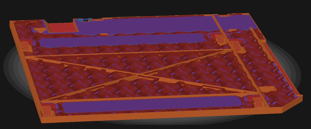
In the image below:
- red marks a ~vertical cavity with a simple perimeter
- green marks a moderately sloped cavity with some added solid infill, which adds material (and time)
- yellow marks full 4-layer top surface under each rising step, which adds a lot of material (and time) -- I get that you have to do something under the non-overlapping perimeters but maybe not all of this
- magenta marks a patch of 4-layer top surface under the flat part -- not complaining about that
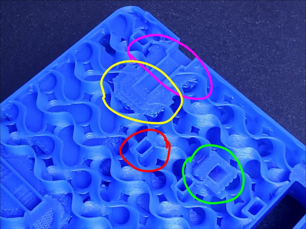
All that infill around slopey walls adds up to a significant fraction of the total material and time in the part. I expect that most of it wouldn't be missed if it went away. Refs linked above suggest this is specifically a PrusaSlicer thing. How many parts would I have to print to recoup time spent shopping slicers to avoid this?
[a] What about Kiri:Moto? I use K:M for CAM and very much appreciate the author's gift of effort to produce that. When I got my 3d printer I printed cubes with default slicer profiles in Kiri:Moto FDM and PrusaSlicer and the latter was the better. And I wanted to print stuff more than I wanted to learn slicer tuning. As a K:M CAM fanboi, I feel a little dissonant about ghosting K:M FDM for no good reason. I'll likely revisit that at some point.
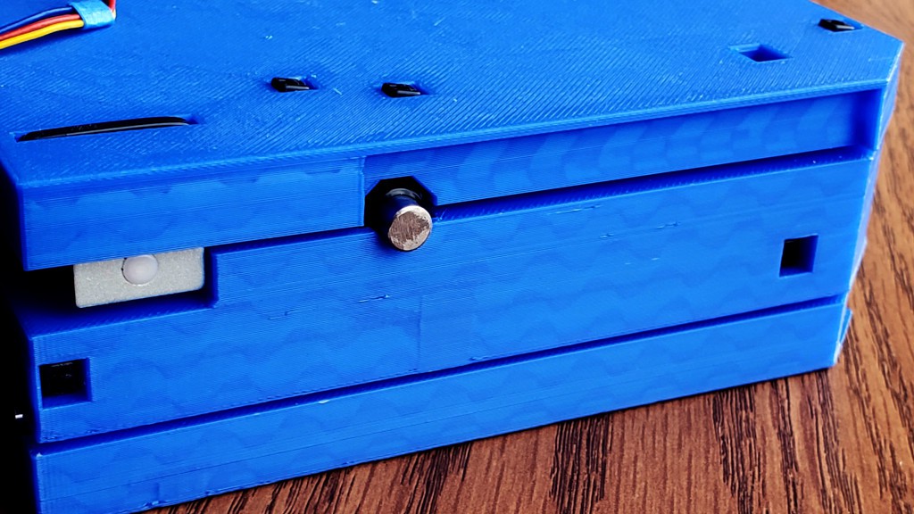
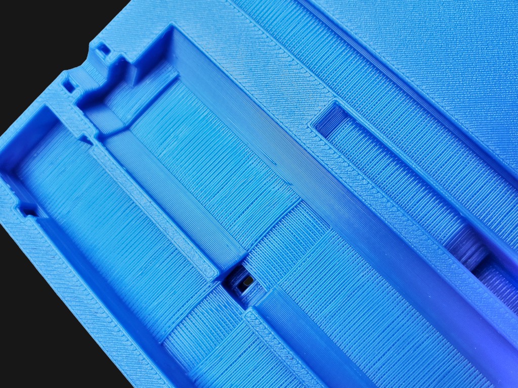
Thin walls + specific reinforcement
The bottom doesn't have to be super stiff because it gets screwed down to something else that is, presumably, more stiff. The thicker middle part is a fairly stiff box structure by itself. The top part not so much. A robust spoil board well attached would stiffen that, but I haven't tried that yet. The "arch" part that projects down into the "middle" space (near corner in this pic) does a lot to help brace a hinge-like stripe of thinness that runs across the top there -- while keeping up the theme of strength from shape instead of density. If I'd thought of that first, I maybe wouldn't have bothered to try a few iterations of adding an internal shape to persuade the slicer to generate specific internal structural reinforcement instead of generally more perimeters or denser infill. But it's there so if you convince the slicer that it's a distinct part with a perimeter, which also implies another perimeter around it in the main part, you'll get some internal reinforcement stringers.
To the slicer, that's two adjacent objects and their perimeters don't overlap. The reinforcing shape is two overlaps thinner than a two-perimeter wall. With "thin wall detection" off, the slicer lays down two perimeters in there anyhow so the volume/density/adhesion of plastic in that space should be the same as in a four-perimeter wall. In theory.
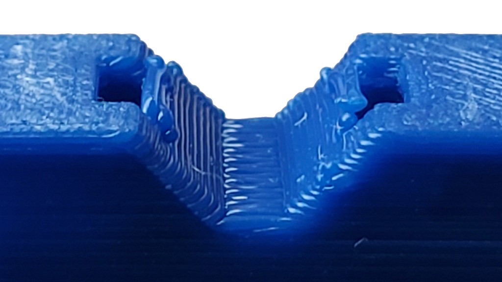
Bridging
Lots of bridging. Over internal voids, mostly for zip ties and cable routing, and over all of the upside down features on the bottom of the middle part.
There are lots "upside down" features. The whole bottom surface of the middle piece is upside down and lots of internal features have upper surfaces. I can't use support in internal features or under surfaces that should be clean and "precise" (relatively for vanilla FDM). So, generally, I've tried to design for printing with no supports. That's been something of a learning curve. Fortunately, the parts that most need to be "precise" are V blocks to locate round things and upside down Vs are easy. In theory. Actually getting clean results has entailed lots of learning lots of ways to not succeed. And, initially, quite a lot of time sitting and staring at the printing printer to see what it was actually doing inside parts.
Slicing bridges
PrusaSlicer, at least, sometimes gets a bridge rwong. I don't know why. It seems quite arbitrary when it happens. A bad bridge might fix itself after seemingly unrelated changes. ?. So I've grown a habit of stepping up the layers in preview to look at every patch of bridge fill over empty space. Fortunately, the preview shows bridges in a contrasting color, which helps with flipping through a bunch of layers until a contrast patch catches the eye. About half-ish of those are bridge areas under voids as the first layer of a patch of "top layer" solid fill (or the actual top) -- a quick flip back confirms whether a bridge area spans open or filled space i.e. above or below a void.
Modeling for bridging...
...and clean corners whether upside down or right side up. In other words, clean details.
I started with some minimal parts just to see if the V-block and zip-tie idea would work at all, and work when printed upside down. It seemed possible in principle because Vs -- 45º slopes and short bridges -- should be easy to print upside down. In principle...
Solving that is how I got into using the Classic perimeter engine instead of Arachne, turning off gap filling, and modeling details around shell thickness, layer height, and overlap math in order to make geometry that would slice predictably where details get close to the dimensions of an extruded line of plastic. Also growing a better feel for geometry that doesn't work upside down and modeling details that are possible to bridge cleanly.
I've probably over-specified a lot of geometry just because I haven't tried to work out which details actually matter.
Alternatively, maybe I (you?) could learn more about what Arachne does and how to model Arachne-safe details, which would probably be more dimensionally flexible.
Discussions
Become a Hackaday.io Member
Create an account to leave a comment. Already have an account? Log In.
Gyroid infill is probably wasting material. Grid infill can probably save material and weight, and might even let you get away with sparser infill.
Very little load is borne by infill anyway, tests have shown that number of perimeters and extrusion width matter a lot more.
Looking forward to seeing where this project goes!
Are you sure? yes | no
Hi Sandro,
My naive "research" turns up mixed information about grid vs. gyroid or other infills. It looks like most of it is people repeating what they've heard, and the few people who actually test stuff don't all arrive at the same simple answer. Do you have any favorite references comparing grid & gyroid? I think it would be great if you want to print and test some of these parts with different infills, different slicers, etc. I agree it does seem possible to use less fill -- I tried 5% briefly but slicer wasn't very smart about spanning large gaps when making patches of "top" solid fill.
I too am looking forward to seeing where this goes :)
Are you sure? yes | no
For gyroid vs. grid, I'm not talking about strength to be clear, just talking about their suitability for bridging, which seems to be your main concern. The geometry makes sense to me: gyriod at any given layer has a small X profile and a large Y profile (or vice versa), where grid or triangle has a more regular pattern with corners that bring the infill much closer together, which is good for bridging. You're right that you'd have to generate them and see whether it actually helps.
Come to think of it, lightning infill is probably the best bet if bridging is the only concern. It places supports exactly where you need them inside the part and nowhere else (typically grown from the walls), so that might get you to near 0% infill.
Gradual infill in Cura also puts more infill density near walls where you might have bridges and less in the internal structure, but I don't think that's available in Prusa slicer.
For strength, CNC Kitchen is run by an aerospace engineering that has done systematic testing on what parameters improve part strength, so he has a bunch of good data:
https://www.youtube.com/watch?v=AmEaNAwFSfI
https://www.youtube.com/watch?v=upELI0HmzHc
https://www.cnckitchen.com/blog/the-influence-of-layer-height-on-the-strength-of-fdm-3d-prints
https://www.cnckitchen.com/blog/the-effect-of-extrusion-width-on-strength-and-quality-of-3d-prints
https://www.cnckitchen.com/blog/gradient-infill-for-3d-prints
https://www.cnckitchen.com/blog/how-the-color-of-pla-filament-influences-3d-printed-part-strength
Hope that helps!
Since reducing the number of parts is a goal, have you considered just printing bushings? With a simple post-processing step I found you can get a smooth, tight fit:
https://www.thingiverse.com/thing:5324484
This is also a good one designed for easy mounting:
https://www.thingiverse.com/thing:1196801
Are you sure? yes | no
Oh - I missed your meaning about bridging. And I hadn't considered it at all. Thanks for mentioning that!
Yeah Stefan/CNC Kitchen does a great job of trying to actually measure a specific thing and present results.
(naked self-promotion: I met Stefan at MRRF last year and we talked at some length. From which came one of his post-MRRF vids: https://www.youtube.com/watch?v=eN3LsQfmXSo . He's really personable in person.)
Printed bushings - that's also a helpful comment! Yes, I had considered them - while working on the laser-cut machine. I didn't try at that time because I had a self-imposed limit of "one fancy machine" and that was a laser cutter for that project so no printed parts. Now that I'm printing parts ... I had completely forgotten about why I wasn't printing bushings! That would be great if it works. I will have to try! (Or anyone else who gets to it before I do -- I'm trying to push out documentation)
Thanks again for two really helpful prompts! That's part of how it's been so helpful to "go public" with this stuff -- including exposure of forgotten decisions that had petrified into unconscious assumptions. Like how the Z axis reboot came from going to MRRF last year: https://hackaday.io/project/174370-minamil-2dc-a-minimal-cnc-mill/log/207938-mrrfx-and-why-rethink-z
Are you sure? yes | no