 Chu Tien Thinh (obitvn)
The story behind this project
In the past decade, we have utilized our superpowers to address various issues all around the world, whether it be creating tools to assist people with disabilities, traversing the depths of the ocean with exploration robots, spanning across rivers and swamps with environmental sensor networks, or harvesting energy from every corner of the Earth, sometimes connecting with satellites in distant skies. But now is the time for us to turn around and craft tools for ourselves. And good tools are the foundation for creating great projects.
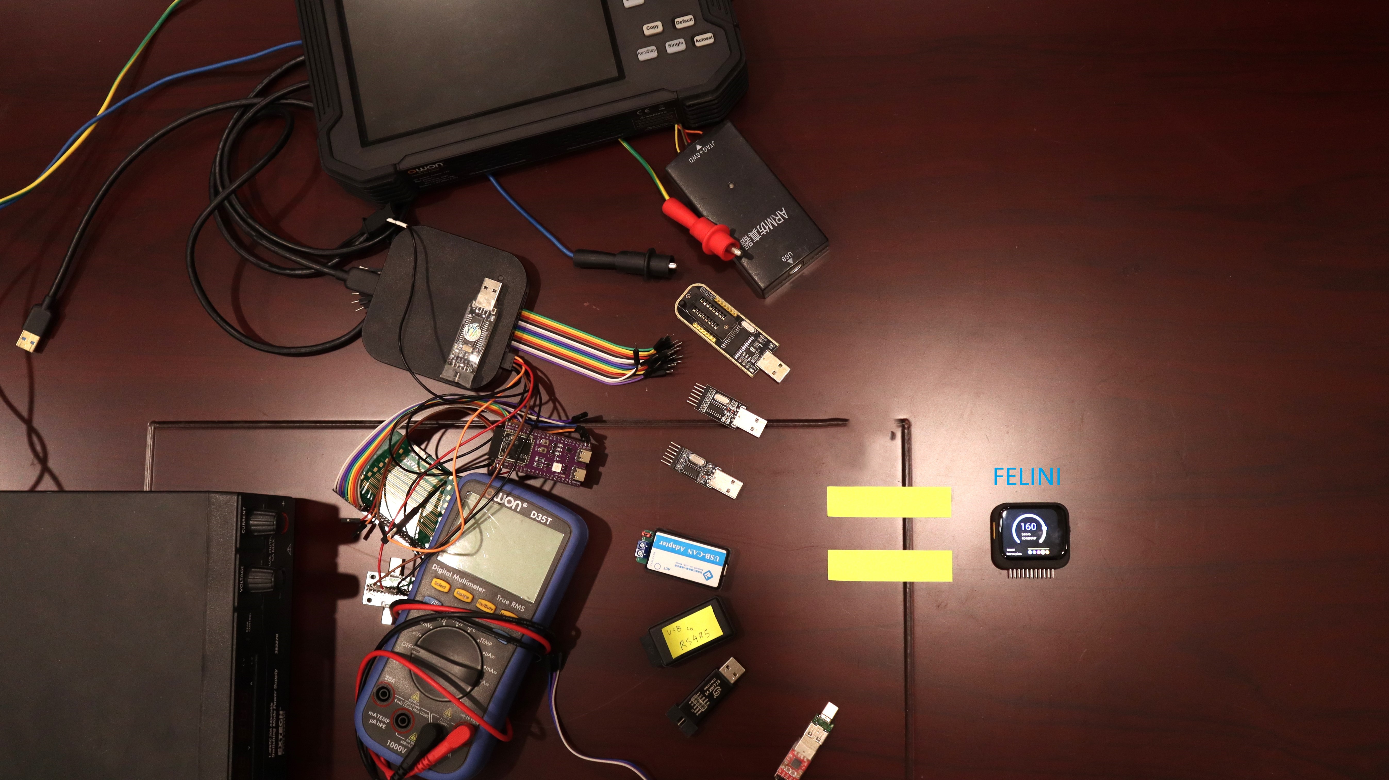
During my student days, my backpack always contained a bunch of tools: a multimeter, a programmer, a USB to UART converter, a power adapter, and a variety of modules, accompanied by a prototype board for continuous programming and research, whether I was in a dormitory, on the campus, or somewhere in a lab. I often envied my IT friends who had nothing but a sleek and simple laptop. Even after graduation, the situation didn't change much; I still carried a small toolbox with items like a logic analyzer, a JLink programmer, adapters, etc. I believe that many people all over the world face similar challenges as I did, and it's time for me to solve this problem.
HACKADAY project goals
After several months of iterations, the project's vision has materialized into what you see in the project's images. My goal is to create a compact device that can fit into a pocket and operate independently without the need for a laptop. In real-world scenarios, such as working with robot circuits, car systems, or indoor sensor networks, it's not always feasible to carry a laptop around. The device's small size and standalone functionality will make it convenient and everyone's favorite pocket companion. For instance, I can read and explore the Canbus network of a hotel even while traveling!
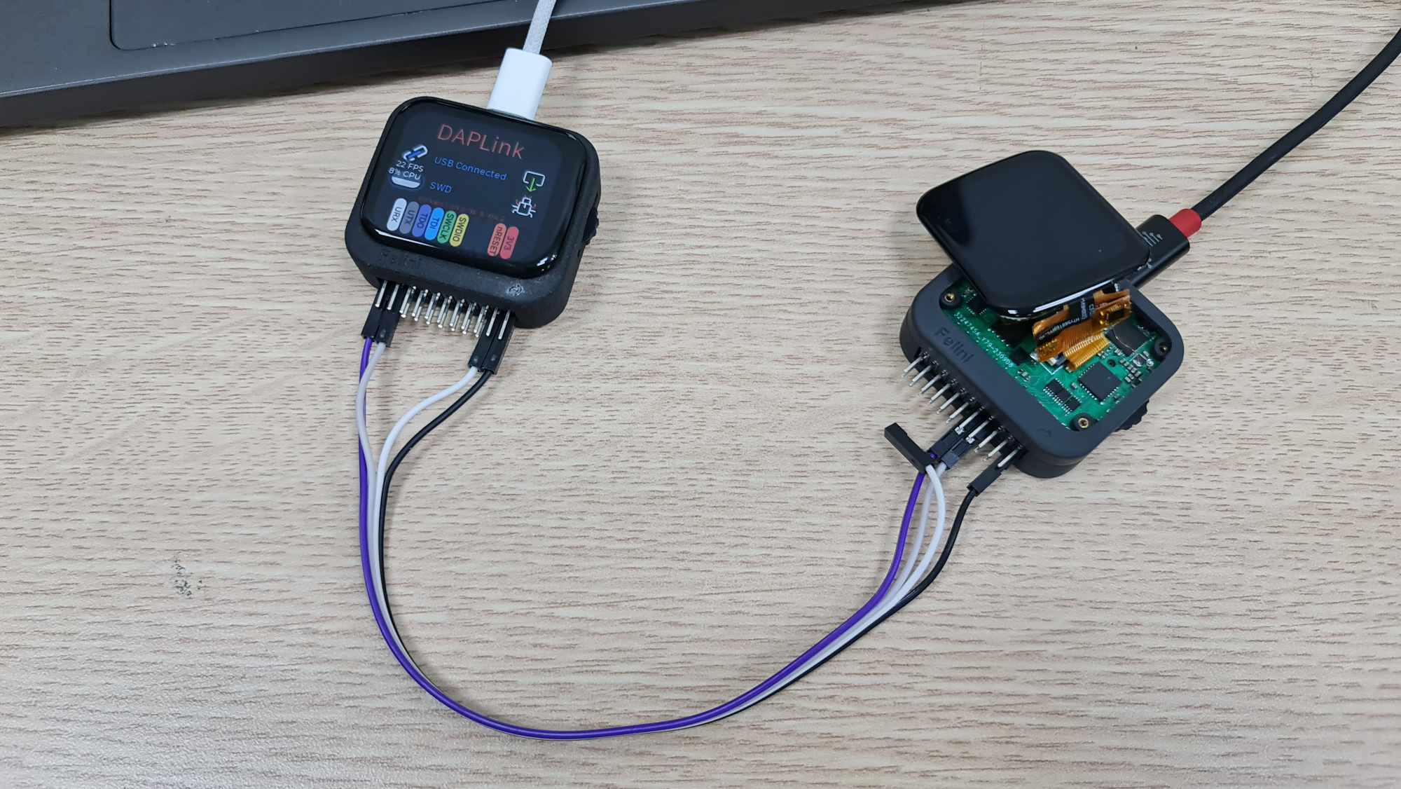
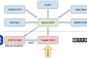
When returning to the laptop, it should seamlessly integrate with the laptop to fully leverage its inherent capabilities. In the past, we've had "multi-functional" devices like Bus Pirate, JTAGulator, FT2232, etc. However, these devices always required accompanying schematics and pinout diagrams, which proved to be quite inconvenient. I don't want to spend additional time browsing the web and searching for this information before plugging the dupont cables into the device. That's why with Felini, the pin map for connecting the wires will appear directly on the screen, making the process much smoother and hassle-free.
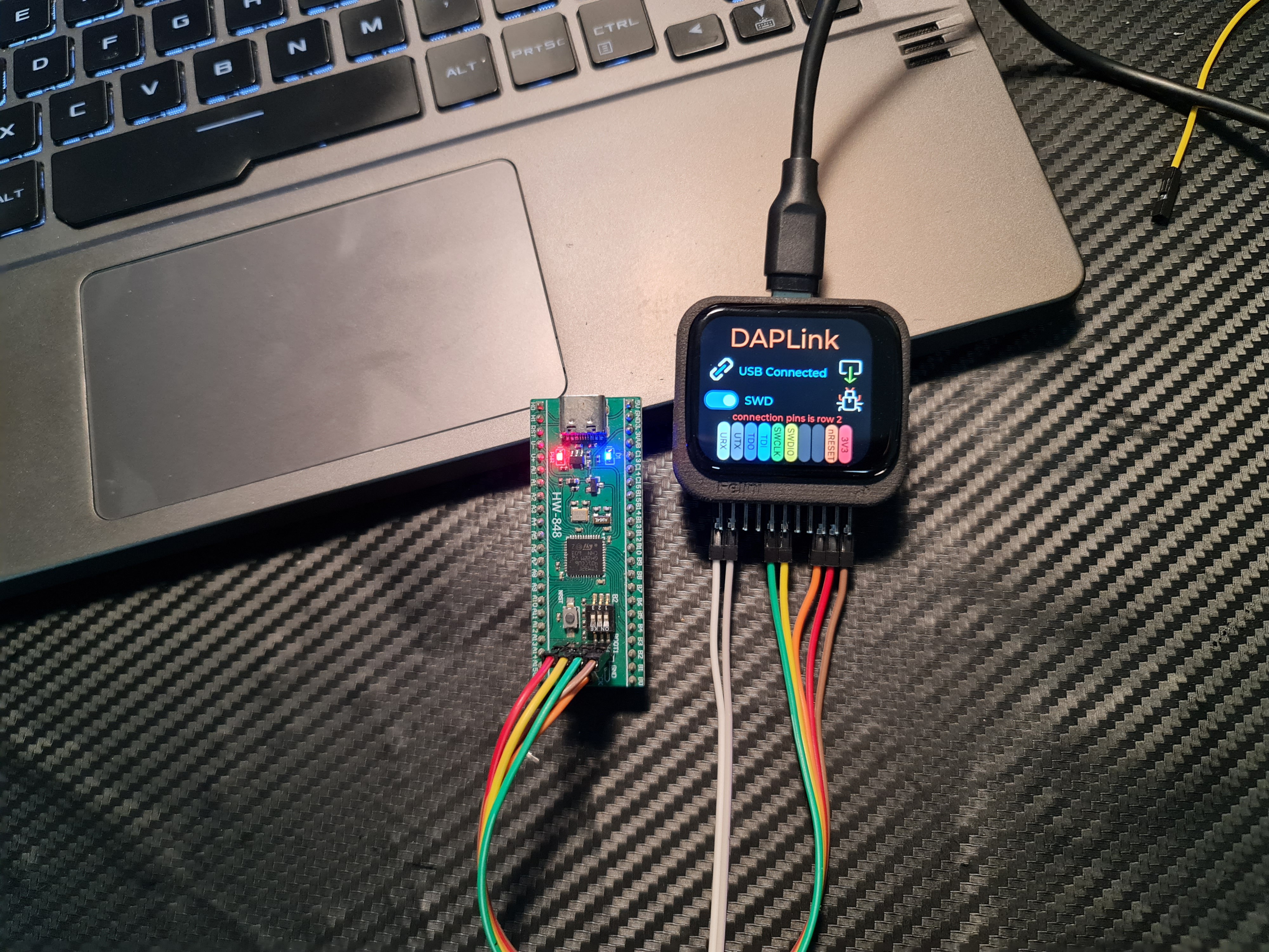
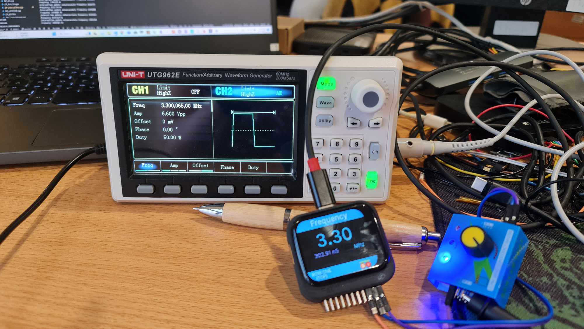
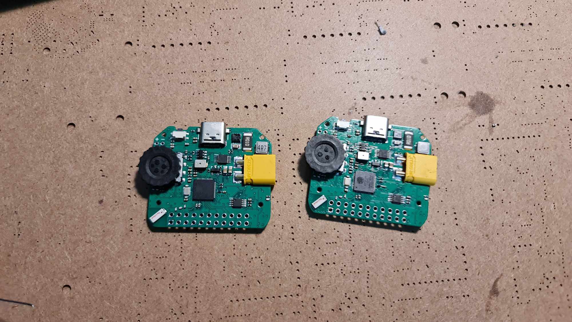
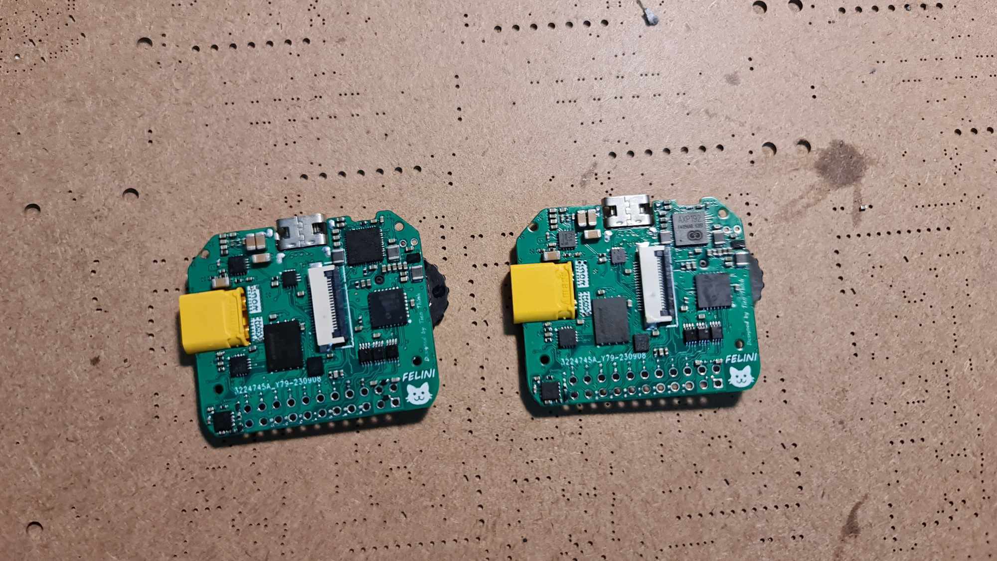
Compared to the initial ideas, Felini has been simplified to be more budget-friendly. The Felini project aims not only at engineers but also at being a user-friendly tool for students. Some common features like DAPLink, Logic analyzer, signal generator, USB to UART/I2C, which do not require external hardware, in the future, when the USB control command stack is completed, can be fully deployed on any affordable esp32 kit available on the market. For the full version of Felini, everything is open-source, from PCB fabrication, SMT component assembly, to enclosure fabrication, all can be done at JLCPCB. Therefore, anyone passionate about electronics can create their own version.
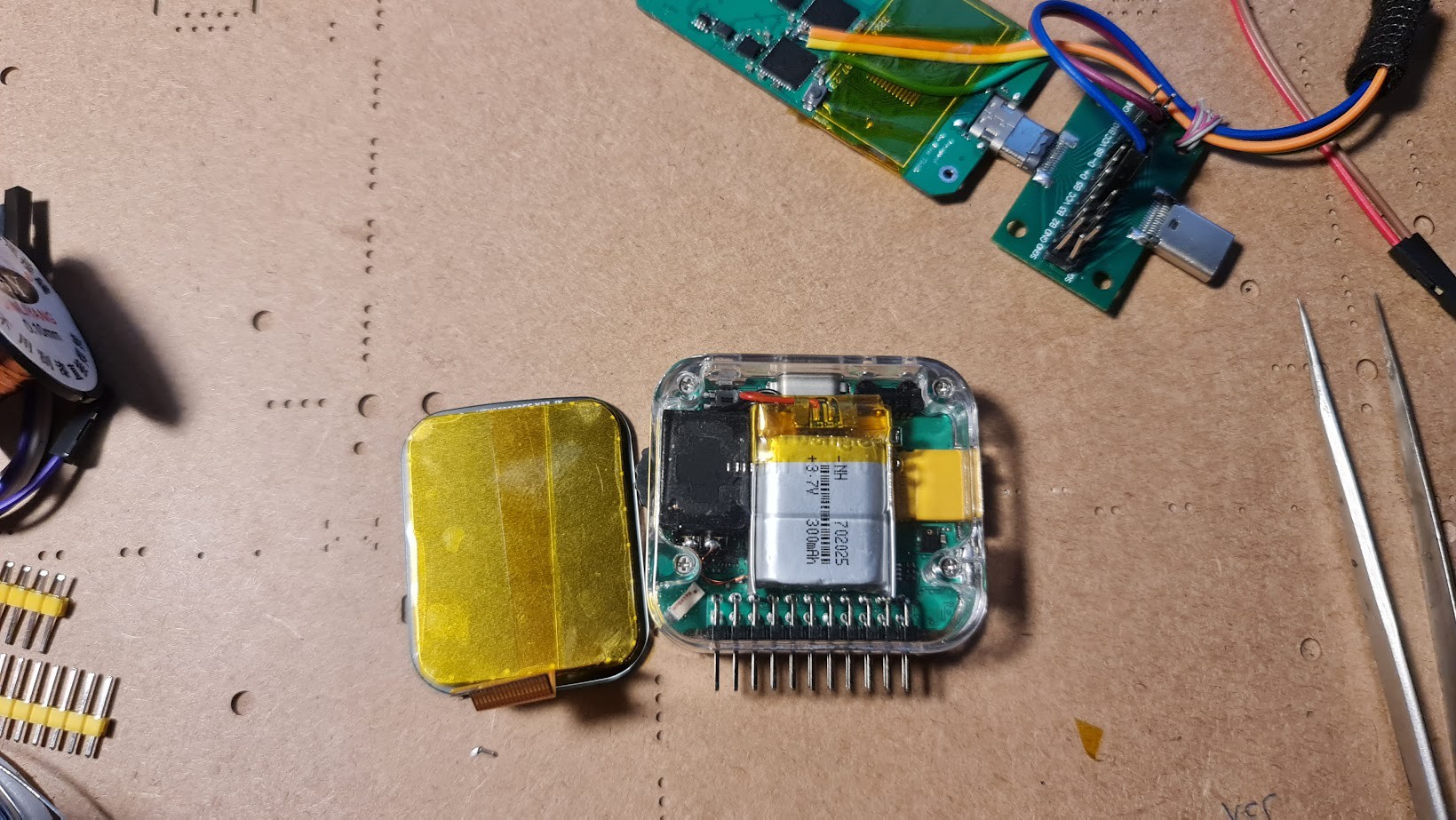
This project is also 100% open source, from a different perspective, as it can directly load firmware through the USB port without requiring any additional hardware, FELINI can be used as a development kit, compatible with both esp-idf and Arduino, allowing students to learn and innovate on an open-source platform. With some minor customizations, such as removing the 2.54mm connector, FELINI can become a wearable MHI or a smartwatch with accelerometers and a display. It can also serve as a health monitoring device for the elderly or a handheld terminal device. It all depends on your abilities. With a cost of only around $50, FELINI is likely a suitable device for many people.
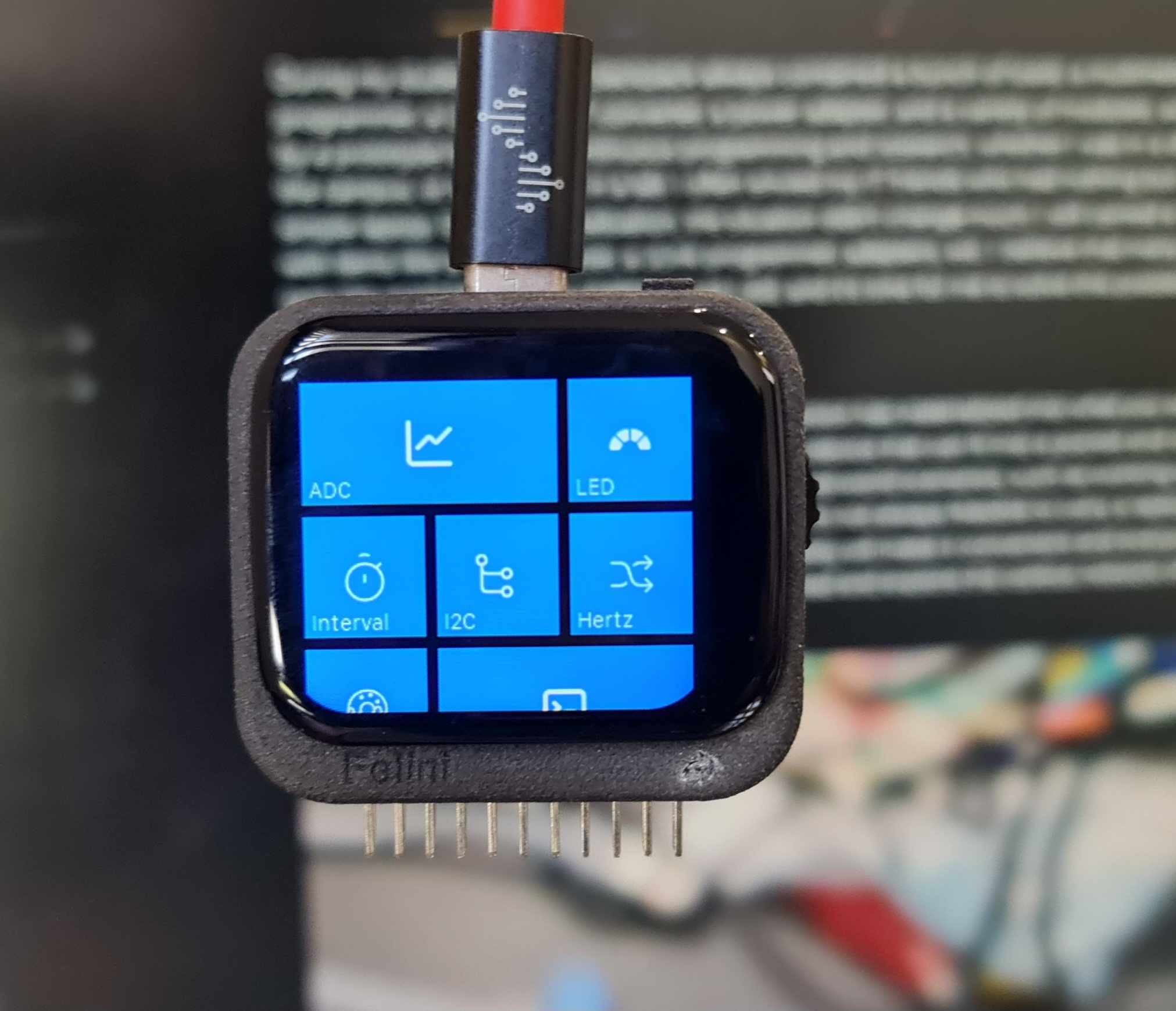
Specs & features
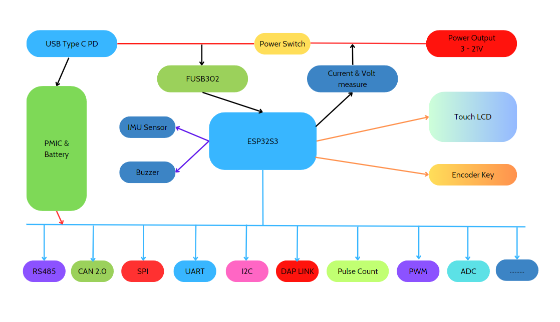
So what can Felini do? Felini was created after three trial versions, striking a balance...
看更多 »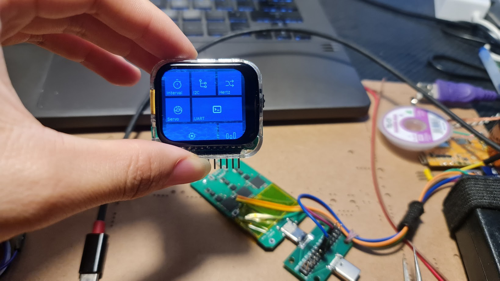


 Mathieu Stephan
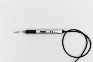
 Nicolas Schurando
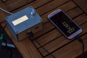
 Lukas Fässler
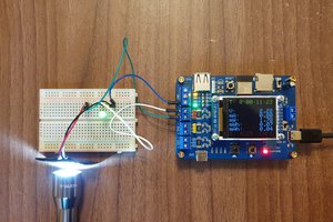
 Ovidiu
Very good project, I have tried to reproduce a version, but I face many problems. First of all, it cannot touch the screen. According to the output of the serial monitor, there should be a problem with i2c. I really have no clue. Please can you Can you give me some help?
I (0) cpu_start: App cpu up.
I (523) cpu_start: Pro cpu start user code
I (523) cpu_start: cpu freq: 240000000 Hz
I (523) cpu_start: Application information:
I (526) cpu_start: Compile time: Jan 11 2024 00:07:11
I (532) cpu_start: ELF file SHA256: 7fc1ab1d91da012c...
I (538) cpu_start: ESP-IDF: v5.1.1-dirty
I (544) cpu_start: Min chip rev: v0.0
I (548) cpu_start: Max chip rev: v0.99
I (553) cpu_start: Chip rev: v0.2
I (558) heap_init: Initializing. RAM available for dynamic allocation:
I (565) heap_init: At 3FCA4C10 len 0002B3F0 (172 KiB): DRAM
I (572) heap_init: At 3FCD2000 len 0000E000 (56 KiB): DRAM
I (578) heap_init: At 3FCE2000 len 00007710 (29 KiB): DRAM
I (584) heap_init: At 3FCE9710 len 00005724 (21 KiB): STACK/DRAM
I (591) heap_init: At 3FCF0000 len 00008000 (32 KiB): DRAM
I (597) heap_init: At 600FE010 len 00001FD8 (7 KiB): RTCRAM
I (603) esp_psram: Adding pool of 8192K of PSRAM memory to heap allocator
I (611) spi_flash: detected chip: winbond
I (615) spi_flash: flash io: dio
I (621) sleep: Configure to isolate all GPIO pins in sleep state
I (626) sleep: Enable automatic switching of GPIO sleep configuration
I (633) app_start: Starting scheduler on CPU0
I (638) app_start: Starting scheduler on CPU1
I (638) main_task: Started on CPU0
I (648) main_task: Calling app_main()
E (652) i2c_manager: Invalid port or not configured for I2C Manager: 0
E (659) i2c_manager: Invalid port or not configured for I2C Manager: 0
W (666) RK816: rk816 id 0x30d version 0x2
E (671) i2c_manager: Invalid port or not configured for I2C Manager: 0
E (678) i2c_manager: Invalid port or not configured for I2C Manager: 0
E (686) i2c_manager: Invalid port or not configured for I2C Manager: 0
E (693) i2c_manager: Invalid port or not configured for I2C Manager: 0
E (700) i2c_manager: Invalid port or not configured for I2C Manager: 0
E (707) i2c_manager: Invalid port or not configured for I2C Manager: 0
E (714) i2c_manager: Invalid port or not configured for I2C Manager: 0
E (722) i2c_manager: Invalid port or not configured for I2C Manager: 0
E (729) i2c_manager: Invalid port or not configured for I2C Manager: 0
E (736) i2c_manager: Invalid port or not configured for I2C Manager: 0
E (743) i2c_manager: Invalid port or not configured for I2C Manager: 0
E (750) i2c_manager: Invalid port or not configured for I2C Manager: 0
E (758) i2c_manager: Invalid port or not configured for I2C Manager: 0
E (765) i2c_manager: Invalid port or not configured for I2C Manager: 0
power on source 0
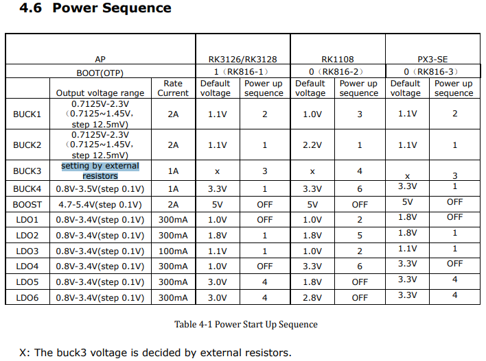
I (774) RK816: dcdc1 712500, dcdc2 1500000, dcdc3 800000,
dcdc4 800000, ldo1 800000, ldo2 800000,
ldo3 800000, ldo4 800000, ldo5 800000, ldo6 12
E (788) i2c_manager: Invalid port or not configured for I2C Manager: 0
E (795) i2c_manager: Invalid port or not configured for I2C Manager: 0
E (803) i2c_manager: Invalid port or not configured for I2C Manager: 0
E (810) i2c_manager: Invalid port or not configured for I2C Manager: 0
E (817) i2c_manager: Invalid port or not configured for I2C Manager: 0
E (824) i2c_manager: Invalid port or not configured for I2C Manager: 0
E (831) i2c_manager: Invalid port or not configured for I2C Manager: 0
E (839) i2c_manager: Invalid port or not configured for I2C Manager: 0
E (846) ledc: ledc_set_duty(710): LEDC is not initialized
E (852) ledc: ledc_update_duty(636): LEDC is not initialized
I (1092) gpio: GPIO[3]| InputEn: 1| OutputEn: 0| OpenDrain: 0| Pullup: 1| Pulldown: 0| Intr:0
I (1093) gpio: GPIO[39]| InputEn: 1| OutputEn: 0| OpenDrain: 0| Pullup: 1| Pulldown: 0| Intr:0
I (1100) gpio: GPIO[38]| InputEn: 1| OutputEn: 0| OpenDrain: 0| Pullup: 1| Pulldown: 0| Intr:0
I (1110) gpio: GPIO[38]| InputEn: 1| OutputEn: 0| OpenDrain: 0| Pullup: 1| Pulldown: 0| Intr:0
I (1119) gpio: GPIO[39]| InputEn: 1| OutputEn: 0| OpenDrain: 0| Pullup: 1| Pulldown: 0| Intr:0
I (1328) CST816: Initializing cst816 0x15
E (1328) i2c_manager: Invalid port or not configured for I2C Manager: 0
E (1329) CST816: Error reading version from device: ERROR
E (1335) i2c_manager: Invalid port or not configured for I2C Manager: 0
E (1342) CST816: Error reading versionInfo from device: ERROR
I (1348) CST816: CST816 version 130, versionInfo: 22.145.1
E (1427) i2c_manager: Invalid port or not configured for I2C Manager: 0
E (1427) i2c_manager: Invalid port or not configured for I2C Manager: 0