 Dr.Stone
Introduction
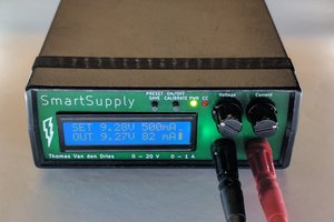
Stuck with only one multimeter/voltmeter ? But, sometimes you need to check 2 or 3 voltages as the same time. Then this is something you might consider making, a real DC voltmeter !
Designed with commonly available components and easy to understand code, can measure both positive and negative voltages simultaneously on 3 nodes in a single circuit or 3 separate circuits.
Demonstration
Hardware
Following hardware are used to build this device:-
- Arduino Uno: Uploading code on the ATmega328P microcontroller
- ATmega328P: 8-bit micro with Arduino Bootloader and built-in 10 bit ADC
- 128x32 1306 OLED Display with I2C interface: Display Voltages
- LM324 OpAmp: Analog signal conditioning for ADC
- 4cm x 6 cm FR4 protoboard: Circuit board for the build
- 10k multiturn pot: Adjusting zero (half AREF) voltage
- TP4056 module: LiPo battery charging
- LiPo battery: 300mAh rechargable battery to power the device

Hardware
Working Principle: AFE Explained
Normally, ATmega328P (Arduino Uno) can measure voltages between Gnd and AVCC range (i.e. 0 to 5V) without any voltage divider resistors network. If internal AREF is enable, it can measure voltages between Gnd and AREF range (i.e. 0 to 1.1 V). With some voltage divider, it is possible to measure higher voltages than 5V. These are all positive voltages with respect to Gnd.
But it can not measure any voltages below Gnd, meaning it can't measure negative voltages. The problem is that, ATmega328P has a single ended ADC, which by default makes measurement with respect to Gnd.
The solution is, don't make measurement with respect to Gnd anymore.
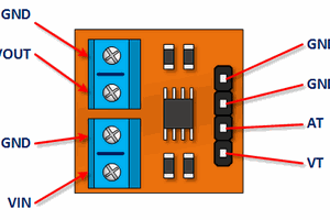
Real voltmeters have COM (Black) and V(Red) terminals, you connect COM to one node, V to another node on a circuit. The voltage reads on V node with respect to COM node.
You need to build an (AFE) Analog Front End, some sort of signal conditioning circuit to generate a COM like behavior. This COM node should have a voltage somewhere in between AVCC and Gnd. Ideally, half AVCC volts but for this design it's half AREF.
When external voltage measurements are taken with respect to COM, you can easily measure both positive and negative voltages !
Please check the following circuit carefully :

Differential measurement with 2 single ended ADC channels
So, what's happening here ? Internal reference AREF is enabled on ATmega328P (from firmware/code in void setup). AREF pin has 1.1 V. Now, ADC measurement has an effective range of 0 to 1.1 volts.
Next, using a LM324 Opamp this 1.1 AREF voltage is buffered, meaning we still have 1.1 voltage from the first Opamp's output. A 10k multiturn trim pot is set exactly to 5k to produce 550mV (half AREF) volts. This 550 mV signal is buffered with the second Opamp. 550 mV signal is also connected to ADC Ch - 0. It should read 512 (half of 10 bit).
There is a voltage divider network consist of 5 Mega Ohms (two 10M in parallel) and 100 Kilo Ohms resistor, which is connected to the output of second Opamp.
I am defining, lower resistor end (100k) as COM and higher resistor (5M) end as V on this voltage divider network. The mid point of this divider is connected to ADC Ch - 1. When no external voltage is applied to this divider, ADC Ch - 1 should read 512 (because of 550 mV)
When an external voltage is applied, the voltage divider mid point voltage will shift above or below 550 mV. If external voltage on V is higher (positive voltage) with respect to COM, it will shift above 550 mV, If external voltage on V is lower (negative voltage) with respect to COM, it will shift below 550 mV. The ADC Ch - 1 reading will change accordingly. Using this change in ADC reading we can calculate external voltages.
Why use AREF instead of AVCC ?
This design is LiPo battery powered, a full charge LiPo will start from 4.2 Volts and gradually the voltage will drop. So, AVCC...
Read more »
 ivoras
 electronicsworkshops
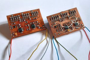
 Thomas Van den Dries