 Xieshi Zhang
-
11Physical Assembly - Lead Screw
- Place a coupler on the stepper motor but don't tighten the screws down yet.
- Slide in the load cell from the hole in the stationary grip all the way to the bearing blocks.
- Position the shaft collars on the bearing and have the raised edge face the bearing. There should be two shaft collars, one on each side of the bearing block.
- Slide the lead screw into the shaft collars and out the other side into the coupler.
- Tighten down the coupler as hard as you can. Use a long allen wrench for this to apply the maximum amount of force you can exert (without stripping the screw).
![]()
-
12Component Selection - Load Cell Amplifier/ADC
The load cell amplifier is used to amplify and read the data from the strain gauge inside the load cell.
Typically, cheap load cell amplifiers use the HX711 IC made by Avia Semiconductor. It consists of an internal programmable gain amplifier and a 24 bit analog-to-digital converter. Its sample rate is selectable from 10 samples-per-second to 80 samples-per-second, which is important to us.
The main options that one can find for cheap (excluding Sparkfun ones) are typically a red type (shown in first picture), a green XFW-HX711 (not shown), and a green MH-HX711 (shown in second picture).
Red:
![]()
Green:
![]()
The part number on those can be confusing, but basically the red type is preferred as long as you use the correct version of the PCB (mentioned later). The reason why is because it has a default 80SPS sample rate and a properly designed circuit, ground plane, and EMI shielding.
- The XFW-HX711 is preferred if you are using the other version of the PCB because it has a selectable sample rate and an acceptable circuit board design.
- The green type shown in the picture is best to be avoided because it is poorly designed and has a non-adjustable sample rate. I will be using this type simply because I have spares of this, but you shouldn't use it. It seems that amazon usually sells this type; however, I would recommend avoiding this type if you can.
-
13Component Selection - Stepper Motor Driver
The stepper motor driver used in this machine is an A4988 on a StepStick format board. StepSticks are usually used with 3D printers and CNC routers, and therefore they are often easily replaceable.
Any A4988 compatible StepStick drivers will work. This includes DRV8825 and some Trinamic drivers in standalone mode.
![]()
-
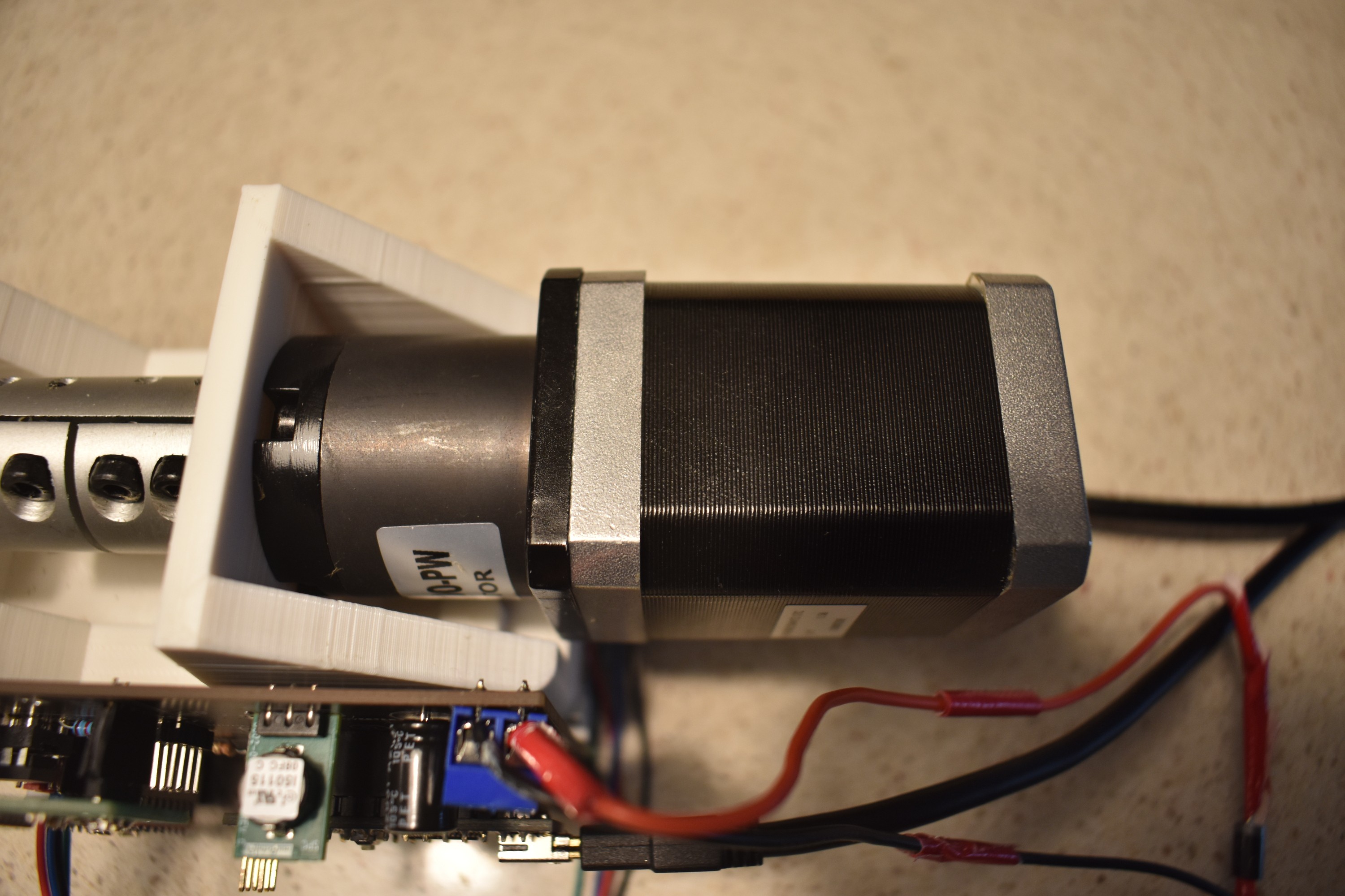
14Component Selection - Stepper Motor
There's a wide range of stepper motors that you may choose from. The model that I used is a 42HS6015A4 100:1 planetary geared stepper motor.
Any NEMA 17 planetary geared stepper motor should work as long as the gear ratio is above 20:1.
If the stepper motor shaft has a key, make sure to select a keyed coupler to match that shaft.
![]()
-
15Component Selection - Arduino & ATTiny
The Arduino is used to interface the computer with serial communication and to also control the OLED display.
An Arduino Nano is preferred, although a Nano Every might work too.
![]()
The ATTiny85 is used to control the stepper motors so that the pulses will be independent of the main Arduino's processes.
It's preferred to use an 8 pin DIP socket with the ATTiny85-20PU so that if something goes wrong, you can replace the chip without desoldering anything.
![]()
-
16Component Selection - Voltage Regulator
This is where you face a choice.
You may choose between an LM7805 or an LM7805 equivalent buck converter. The LM7805 is generally cheaper and produces less noise; however, it also generates around 0.9W of heat in this application, so you may need a heatsink. On the other hand, a buck converter can cost three times as much as the LM7805 but is able to be very efficient and dissipate very little heat.
On the first iteration, I chose a buck converter from Aliexpress. On the second iteration, I chose a buck converter from Murata.
![]()
-
17Component Selection - Others
The OLED display needs to be a 128x64 SSD1306 I2C display. Make sure the polarities are correct.
![]()
- Pin headers: use any generic male and female 2.54mm pitch pin headers.
- Terminal block: use KF301 or other connectors with the same pitch.
- Stepper motor/endstop connectors: use XH-2.54 connectors.
This is a tutorial on how to cut the female headers.
![]()
You may use a B3F-4000 switch. There are other switches that have the same pinout, but this works well for me.
![]()
The passives are much more flexible in terms of selection.
Generally, the capacitors are simply not needed if you're using a quality power supply and a good load cell amplifier. However, they're still recommended.
- Capacitors: use a 100uf >35v electrolytic capacitor for the stepper motor power. In this case I have 100uf 50v lying around, so I'll be using those. You may also want 1210 ceramic capacitors for decoupling (I know that 1210 isn't the best package size, but it's easy to solder).
- Resistors: use 1k-10k resistors. It doesn't matter if they're 1/4W or 1/8W or if they're carbon or wire-wound. As long as they fit the PCB and are in the recommended range, they work just fine. You may also want a 330 ohm resistor for the optional LED.
![]()
-
18Electronics Assembly
The assembly process is pretty straightfoward. Simply solder the required components onto the board and plug in the parts. Make sure to double and triple check the polarity and component orientation or else magic smoke will escape (it happened for me, but don't worry, the problem is fixed).
On the newer version of the PCB, you will see a place for adding a diode. You can either bridge the jumper on that part using a solder bridge or add the diode. If you choose to not populate the diode and instead use a solder bridge, you must desolder the USB diode on the Nano to avoid overcurrent on the USB. Keep in mind that USB power itself cannot power the whole board due to excessive capacitance.
I also recommend adding a schottky diode in series with the power source to ensure that no reverse polarity can happen.
![]()
![]()
-
19Electronics Assembly - Arduino Code
The code can be found on GitHub.
-
20Electronics Assembly - Set Parameters
These are the parameters that need to be set before you upload the code.
PLX-DAQ Excel Data Acquisition
This parameter can be enabled if you will use PLX-DAQ to acquire and analyze the data. The integration of PLX-DAQ is requested from a comment from the original tensile testing machine's instructable.
You need to set up PLX-DAQ in Excel to be able to record the data. I have NOT tested this, so I don't actually know if this setup will work or not. But for those who are interested in using PLX-DAQ, this is an option that probably works.
Calibration Factor
Each load cell has a different calibration factor. You will need to calibrate your own load cell using a known weight through Bogde's instructions.
Steps Per Revolution
1.8 degree stepper motors have 200 steps per revolution, while 0.9 degree stepper motors have 400 steps per revolution. Set this parameter to the value corresponding to your stepper motor.
Microstepping
The microstepping value depends on the microstepping jumpers you set for the stepper motor driver. Set the value corresponding to the microstepping value.
Lead Screw Pitch
I'm using a 2mm pitch and 8mm lead lead screw. Therefore, the pitch I set here is 8mm because the nut moves 8mm per revolution. You may have a lead screw with a different pitch.
Speed Multipliers
Set this to the speed that you wish to test the specimens at.
Modulus Threshold
This is the time threshold in milliseconds you wish to have the modulus test mode turn into fast mode.
Read Attempts
This purely depends on the sample rate of your load cell amplifier. If you're using the red HX711 or one that is set to 80SPS, use 8 for the read attempt number. Otherwise, leave it at 1.
![]()
Low Cost Universal Tensile Testing Machine
An extremely low cost universal tensile testing machine made from 3D printed and commercial materials


Discussions
Become a Hackaday.io Member
Create an account to leave a comment. Already have an account? Log In.