 Xieshi Zhang
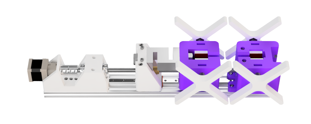
What is a universal tensile testing machine?
Tensile testing machines are variants of universal testing machines made specifically to test tensile strength of materials. It applies a tensile force to a specimen (stretches it) until it breaks, and measures the forces applied while doing so. Although this specific machine is built with mainly tensile testing in mind, this version is able to perform compression tests as well.
Benefits over commercial universal testing machines:
- Significantly cheaper (costs around $300 versus $12,900-$150,000)
- Customizable (Arduino programed)
- 3D printable and accessible
- Open source
Commercial tensile testers are extremely expensive. While they produce accurate and highly repeatable results given the right conditions, many material testing situations, especially for rapid prototyping, do not require the precision and accuracy that those machines give. They cost from 12,900 to 150,000 depending on the model! There is a need for low cost material testing systems for low strength materials, and that's where my UTTM comes in. For only $300, you get a machine capable of testing strengths up to a kilonewton with repeatable results (see research projects in logs section).
How does it work?
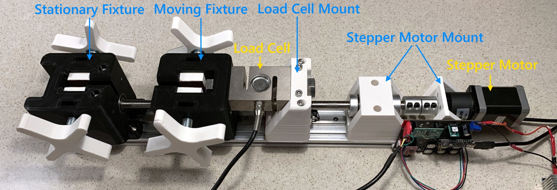
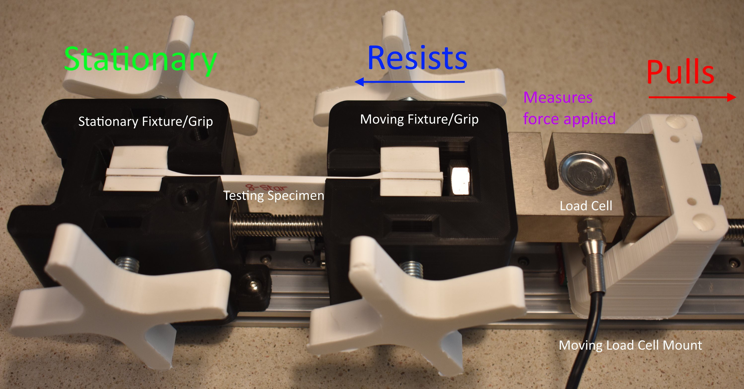
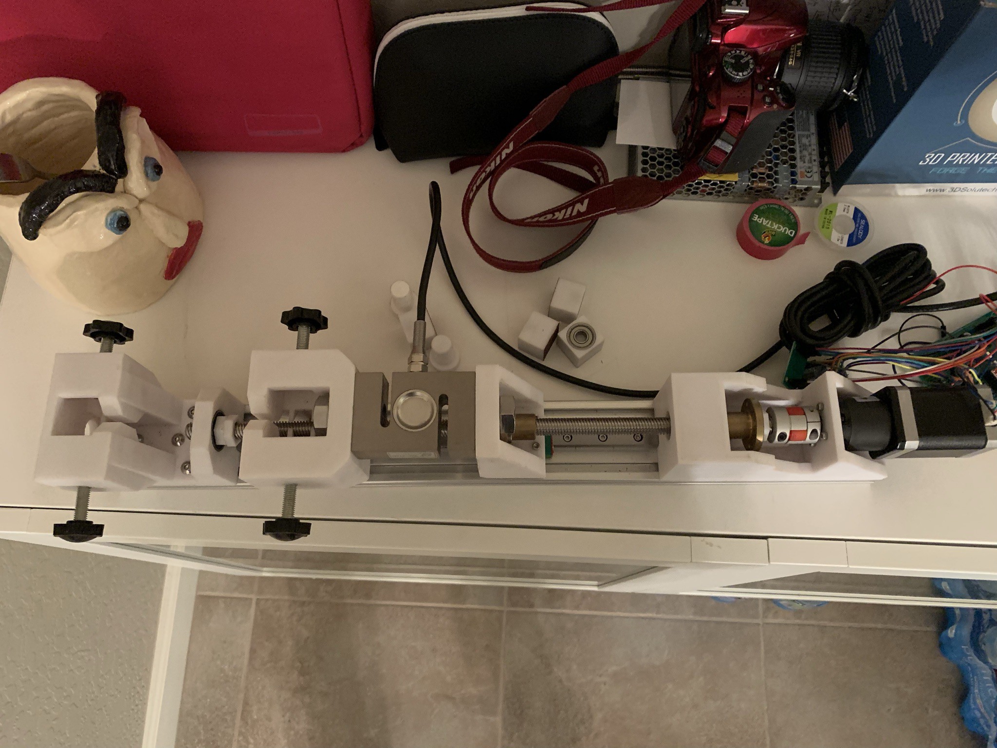
This tensile testing machine has mainly five parts: the stationary fixture, moving fixture, load cell (and its mount), and the motor (a geared NEMA 17 stepper motor). The moving fixture is attached to a load cell and controlled by the motor via a lead screw. After the specimen is loaded and a tensile test had begun, the motor rotates the lead screw. The lead screw translates rotations into linear motion, causing the load cell to be pulled back, but the specimen resists the pulling force by exerting an equal and opposite reaction, which is then measured by the load cell. This process continues until the specimen fractures. The same process is used for compression tests, except the specimens will be loaded in the opposite direction.
Here is a video of it in action:
Background:
I am currently a senior in high school. I began this project in 8th grade.
This project began in 2019, and its two iterations were published on Instructables in 2020 and 2021. The original iterations were featured on Hackaday and Hackster. Version 1.0 featured breadboard electronics and a crudely designed frame in Tinkercad. This was used in my research project published on Journal of Emerging Investigators. After a year of redesign work, a brand new version was born under the version 2.0 and published on Instructables. This version was built by some mechanical engineering students, including a Duke University student, who used it for their Capstone Project.
Image from Duke University MEMS MS Capstone
The version posted here is a sort of 2.1 iteration. I am working on reworking the electronics as version 2.0 had many issues with the stepper motors. Unfortunately, as a stressed out high school student, school work has kept me extremely busy, so the project fell out of maintenance for a year.
For those of you who have looked at my Instructables, you will notice that most of the steps here are the same since I have no reason to change the assembly instructions.
Do I need advanced electronics knowledge to build this?
You will need basic intermediate knowledge to solder the components onto the PCB. Most of the components are through-hole, and those that are SMD are not strictly required. By following the build instructions, you should be able to replicate the machine without much experience in electronics, but if you plan on customizing some features, then you need to be familiar with the required skills.
Acknowledgement
I want to thank the following people/organizations who helped in making this project possible:
- Student Makers (for funding)
- CNC Kitchen (for inspiration & extensometer code)
- Daniel Lin (for helping in the first version of the machine and co-writing our research paper)
- My...
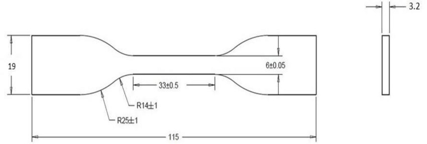

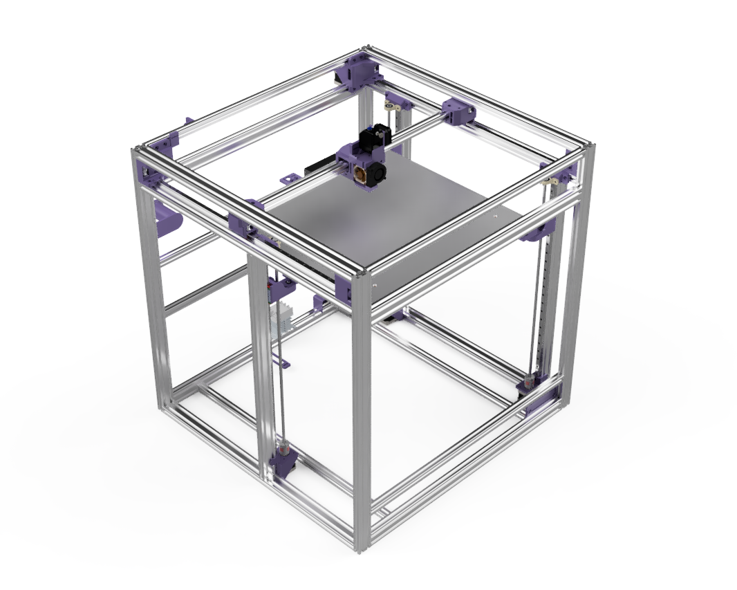
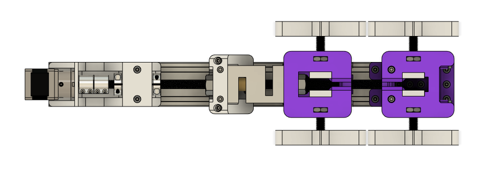
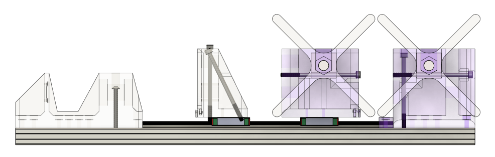
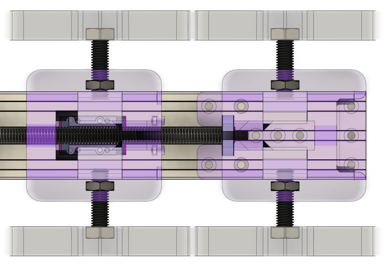
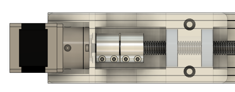


 Image credit goes to Parallax Inc., the company that developed this amazing tool.
 The idea was born when I was an 8th grade student at Arizona College Prep Oakland Campus looking for inspiration for Science Fair. A YouTuber I watched, CNC Kitchen, tested the tensile strengths of 3D printed specimen on his videos, and I decided to replicate his experiments for my own Science Fair project.
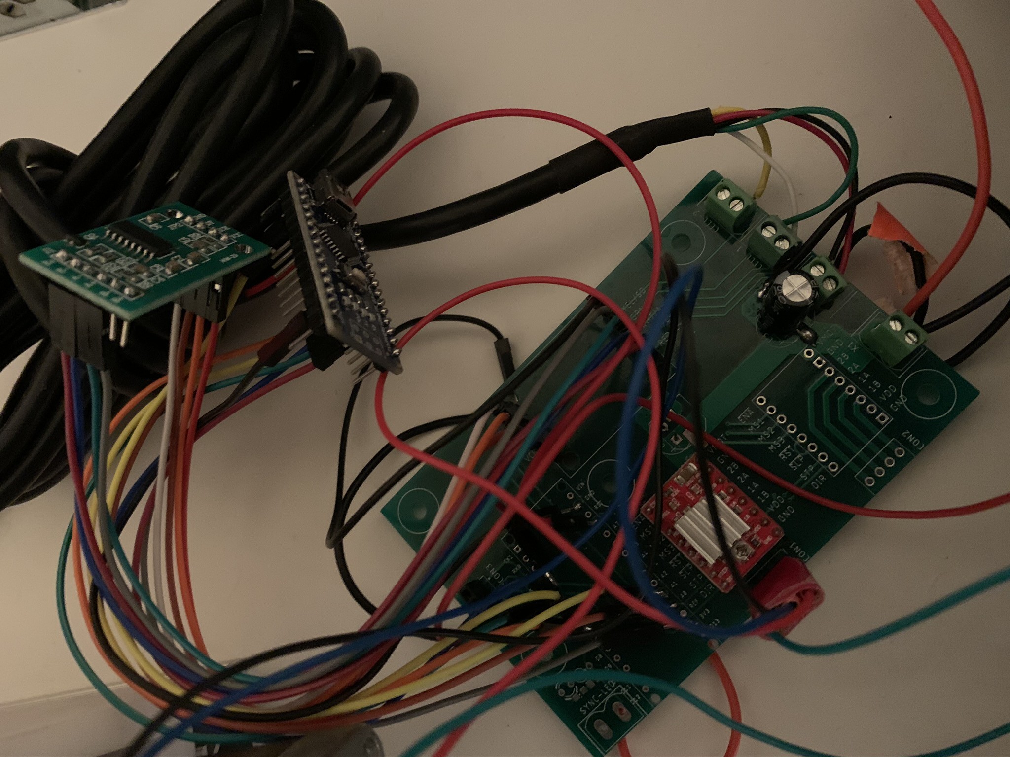


 PETG Specimen strain testing:

 Graphs:


 DevLab.nrw
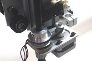
 Juha Kuusama
Interesting project! Wire crimp terminals are actually tested by the pull-out force, so this could probably be used for that as well. Although, this probably provides much more precision and data than crimp terminal testing really needs.