Xieshi Zhang
-
Video of a Tensile Test
08/06/2023 at 07:35 • 0 commentsMarker dots were put on to later be processed for extensometer data. I will provide the steps to do so in a later update.
-
Recommended Testing Specimen
08/06/2023 at 00:47 • 0 commentsThis machine is designed for use with dogbone type plastic tensile testing specimen that break under 1kN of force. I recommend the ASTM D638 Type IV Specimen.
![]()
-
A History of This Project: The Second Version
08/05/2023 at 05:08 • 0 commentsVersion Two
![]()
With all the flaws in mind, I redesigned the machine in Fusion 360. This was while I was designing a large scale 3D printer known as the Blackstone Cube (I still haven't published it yet).
![]()
The design went surprisingly smooth. With knowledge from the first version, I was able to finish it and build it within a few months. Of course, no electronics-related project would not be complete without its rite of passage - the magic smoke.
![]()
That was not the only component I blew up. I took out an electrolytic capacitor, stepper motor driver, and my mom's computer's USB port, all due to a reverse polarity mistake. It was at this moment I realized the true power of tantalum and electrolytic capacitors.
I developed some temporary trauma due to that.
Now let's get to the serious business and talk about what changed compared to the previous version.
![]()
List of Improvements:
Hardware:
- Ability to perform compression tests
- Much less fixture deflection due to reinforcements
- Much stronger grips
- Shaft collars instead of flanged nuts to save space
- Higher torque transfer
- Designed in Fusion 360
- More clearance in mounting holes
Electronics:
- Custom PCB for a more permanent electronics solution
- Buttons and OLED display for testing without computer
- Emergency Stop/Reset All button
- Many more testing modes, including speed selection and modulus testing.
- Support for PLX-DAQ data acquisition
- Dedicated ATTiny85 for separate stepper motor controls
- Easy to configure Arduino code
From my testing, this new version is able to handle at least 1kN of load.
Let's look at them in more detail:
One of the previous issues was hull deflection/flex under load. This shouldn't affect the maximum readings to a significant extent until the flex starts to introduce forces not parallel to center line of the specimen. To solve this, I've added bolt reinforcements to the machine and improved the structure.
![]()
I'm no physicist, nor have I taken MechE classes, so to be frank, I don't know if the bolt placements are the most optimal. I do know that they should provide at least some reinforcement.
The grip blocks now have nut inserts to aid against stripping and greatly increases clamping force by the fixtures.
![]()
Better pillow blocks using shaft collars allowing longer couplers and higher load.
![]()
These are just a few of the mechanical improvements.
The electrical improvements center around the PCB.
![]()
![]()
The old electronics suffered from the motor stopping every time the Arduino reports the load, so as a result I rewrote the code and added in an ATTiny to offload the task of controlling the motors. Although I have to admit that it was tricky to get the ATTiny to work with i2c commands and took me and others quite a few tries.
The new version features an Emergency Stop button (I just recommend unplugging the power if there is an emergency. Emergency Stop freezes the Arduino to prevent it from sending further signals, but the stepper motor is still powered. I'm working on addressing this in the newer versions).
There is also experimental support for PLX-DAQ, a data collecting tool in Excel.
![PLX-DAQ Updated For Excel/Windows 10 And Propeller 2 Early Adopter Progress - Parallax]() Image credit goes to Parallax Inc., the company that developed this amazing tool.
Image credit goes to Parallax Inc., the company that developed this amazing tool.Once again, I published the machine on Instructables, winning a place as Runner Up on the Instructables 1000th contest, a rather disappointing result considering my efforts.
-
A History of this Project: The Beginning
08/05/2023 at 03:04 • 0 commentsI don't mean to share a story that you're going to be bored reading, nor am I trying to picture myself as an "inspiring youth inventor". I am an ordinary maker just like anyone else. I hope that this can help other young makers realize their potentials, if anyone reading this is young.
The Beginning
This is the first version of the machine:
![]() The idea was born when I was an 8th grade student at Arizona College Prep Oakland Campus looking for inspiration for Science Fair. A YouTuber I watched, CNC Kitchen, tested the tensile strengths of 3D printed specimen on his videos, and I decided to replicate his experiments for my own Science Fair project.
The idea was born when I was an 8th grade student at Arizona College Prep Oakland Campus looking for inspiration for Science Fair. A YouTuber I watched, CNC Kitchen, tested the tensile strengths of 3D printed specimen on his videos, and I decided to replicate his experiments for my own Science Fair project.With some previous knowledge building hobby projects, including a 3D printer designed entirely in Tinkercad (yes, Tinkercad...I know...). I decided to design a tensile testing machine along with my friend, again in Tinkercad. It took us a few months to do so.
Check out the design on Tinkercad.
Unlike this version presented today, I decided to use CNC Kitchen's tensile testing machine PCB, which ended up being a horrible idea, resulting in this:
![]()
The person who designed this PCB did not realize that through-hole pads need pins to GO THROUGH the holes.
That's not all. I don't have a picture for it, but I ended up blowing everything up because I plugged the stepper motor driver in the wrong way.
Here is another lovely picture, featuring my also eighth grade art project.
![]()
This version of the machine had many problems, including but not limited to: large flexing/deflection, coupler slipping, specimen slipping, and fixture screw threads stripping. Some of them were "solved" by temporary patches such as this "dogbone" specimen.
![]()
It ironically resembles dog bone more than most standard dogbone shaped specimen.
Either way, the machine worked.
![]()
The process didn't go without a hitch, but I managed to finish it. My friend and I used the design for our Science Fair projects, where I tested the effect of layer height on tensile strength, while my friend tested the effect of infill type on tensile strength (we completed it on the day Science Fair was due). My friend went to Broadcom MASTERS, but we decided to co-publish a paper on our findings.
I later submitted to the Tinkercad Student Design Challenge on Instructables and won First Prize. I promised to make a second version and publish it on Instructables.
The design and assembly processes for my first tensile testing machine are featured on my Instructable. The project was featured on Hackaday.com and Hackster.
Here is a video of it in action:
To all the young makers out there: you can do it! It's never too early to express your creativity to the world!
-
Research Project: A Comparison of the Mechanical Properties of PLA, ABS, and PETG Specimens Produced by Fused Filament Fabrication (3D printing) after Water Submersion
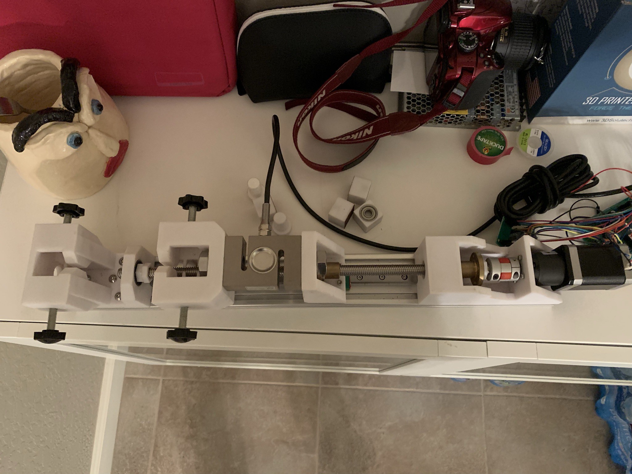
08/03/2023 at 06:43 • 0 commentsThis research project was submitted to the Arizona Science and Engineering Fair in 2022. It uses the tensile testing machine. It is shown here:
This study focuses on comparatively analyzing the effect of time submersed in water on various 3D printing materials (PLA, ABS, and PETG) on their mass change and ultimate tensile strength.
Methodology:
Overall Procedures:
- Use the 3D printer to print 12 ASTM D638 Type IV Specimens with each of the PLA, ABS, and PETG filament.
- Label each type of specimen with their material type and number, such that the first PLA sample would be labeled as PLA-1. Place black marks on two ends of the breaking region of the printed specimens on the narrow side of the specimen.
- Weigh each of the specimens and record the data.
- Load each of the specimens and operate the universal tensile testing machine in fast tensile testing mode. Record the data.
- Pour 3 liters of water into each container and place the lid over the boxes. Adjust the water temperature to 23 degrees Celsius.
- Place three specimens of each material type into the containers oriented with the text facing up.
- After 12, 24, and 36 hours, take the specimens out and dry them with a lint-free paper towel.
- Repeat steps 3 and 4 for each of the 12, 24, and 36 hour levels.
3D printer (Ender 3) with ABS specimens:
PETG Specimen strain testing:
Specimen Type: ASTM D638 Type IV
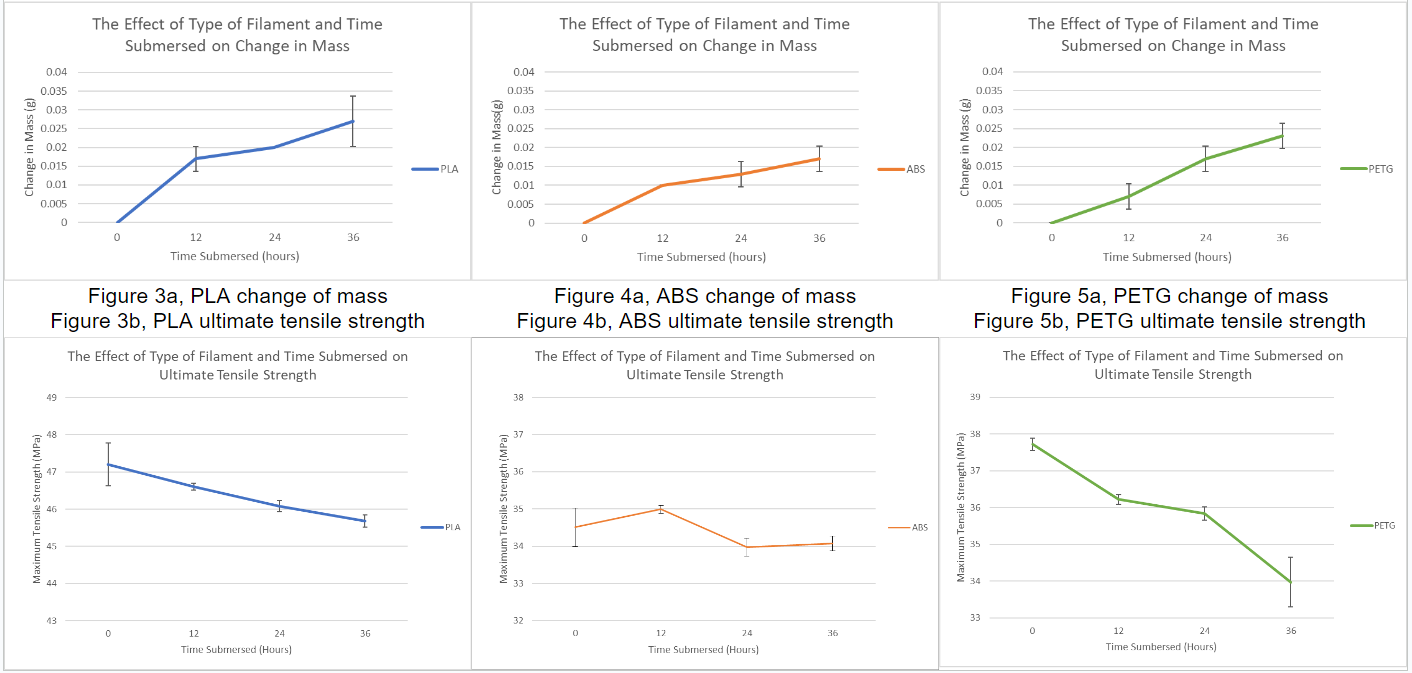
Results:
Tables:
Graphs:
Discussion:
This experiment comparatively evaluates the relation between ultimate tensile strength and mass change as a result of different types of plastic submersed in different amounts of time in water.
The hypothesis was partially supported, and the outcomes of this experiment demonstrates that based on the results
- PETG may have experienced more degradation compared to PLA, but it may be less hygroscopic.
- PLA may have experienced less degradation compared to PETG, but it may be more hygroscopic despite the lower degradation.
- ABS, as predicted, had most likely experienced the least degradation and is the least hygroscopic.
Low Cost Universal Tensile Testing Machine
An extremely low cost universal tensile testing machine made from 3D printed and commercial materials
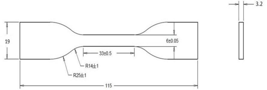

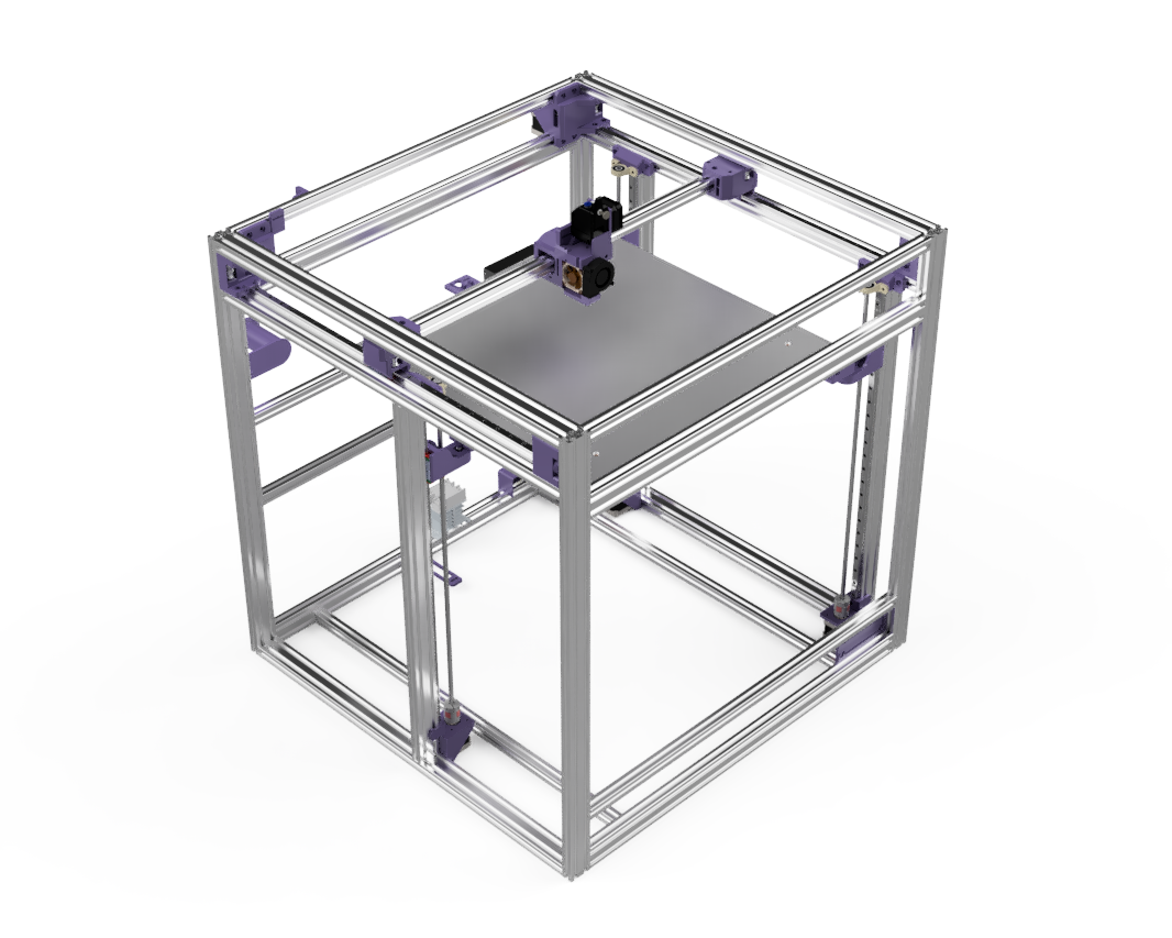
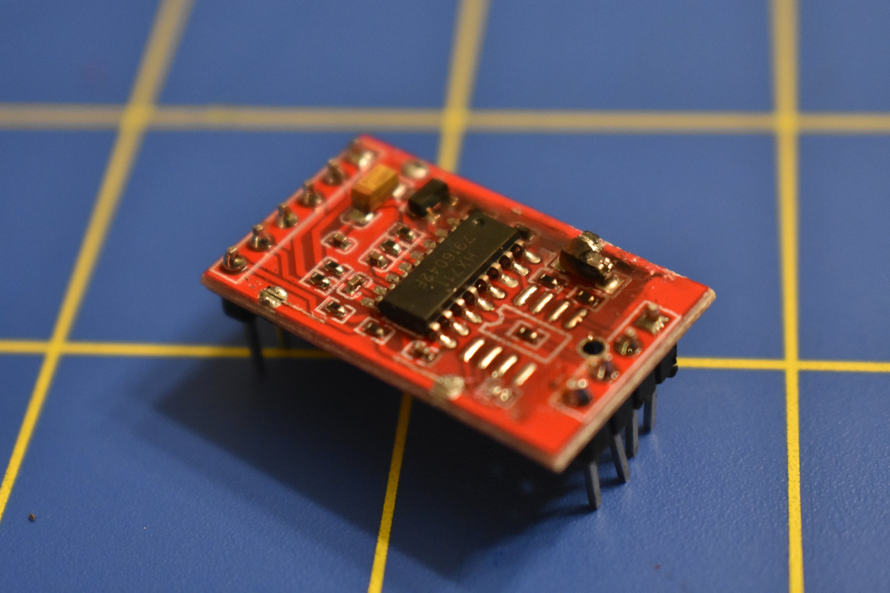
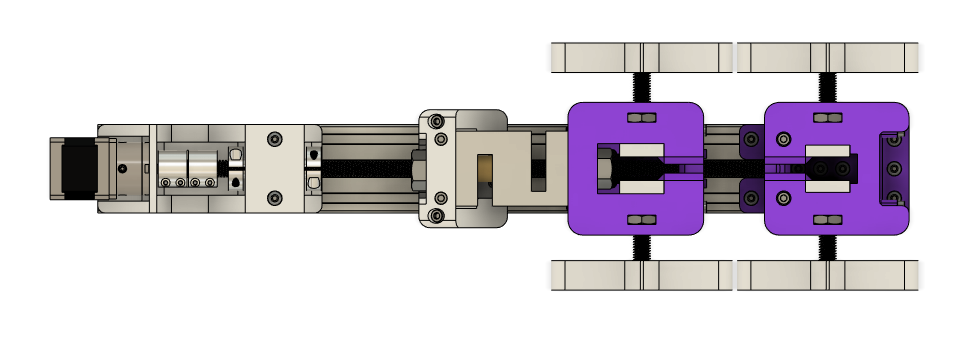
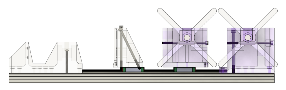
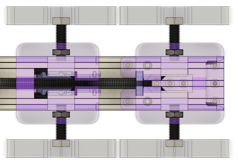
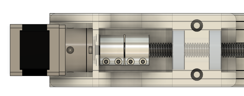


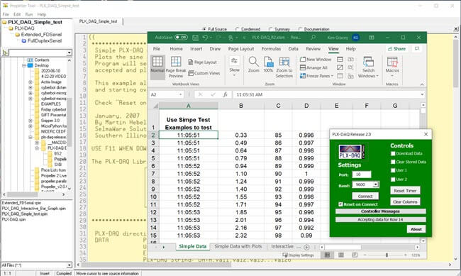 Image credit goes to Parallax Inc., the company that developed this amazing tool.
 The idea was born when I was an 8th grade student at Arizona College Prep Oakland Campus looking for inspiration for Science Fair. A YouTuber I watched, CNC Kitchen, tested the tensile strengths of 3D printed specimen on his videos, and I decided to replicate his experiments for my own Science Fair project.
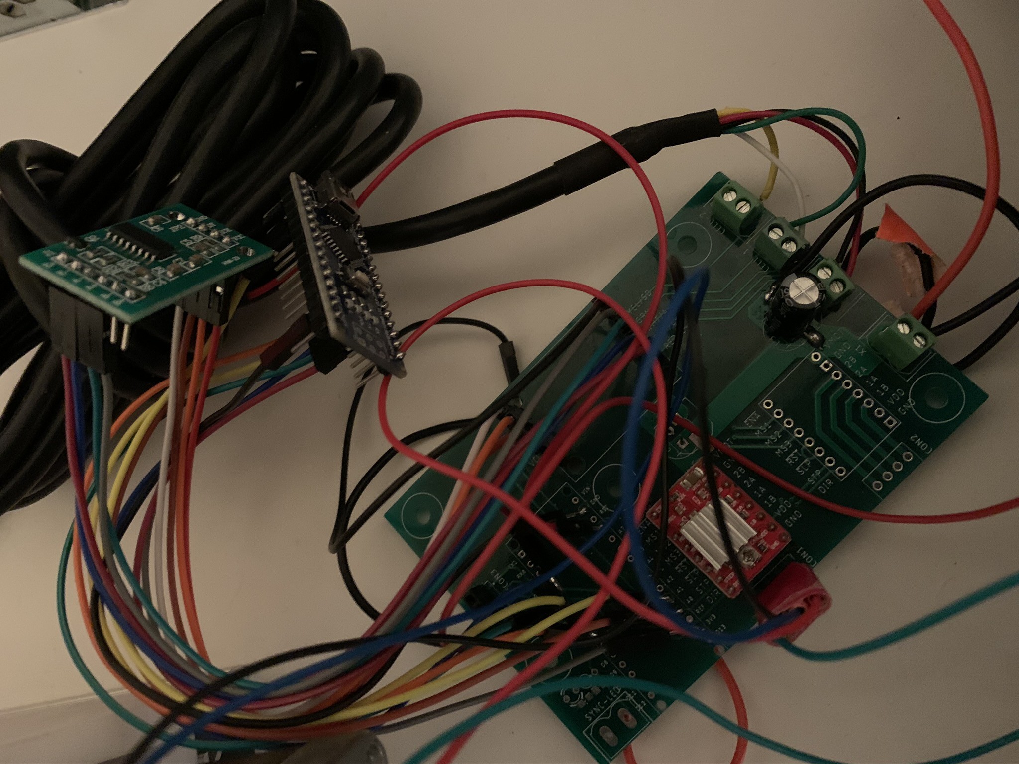


 PETG Specimen strain testing:

 Graphs: