 Curtis Soldano
This project didn't start with a super specific goal in mind and the fact I've come to a final vision is really a culmination of a number of factors. Those factors include the size of the case I decided to buy, maybe because I am cheap I chose one on the smaller side, lol. I knew I intended to use a Pi and I wanted minimum 7" screen for visibility. I really wanted to go a little bigger but each decision has cascading repercussions so I stayed with 7 but mostly because that's what I already had. Seeing the Hackaday projects like Cyberdeck1,, "cyberdeck mobile command center" with its swing out mounts and the project by Daniel Roseman are very similar to what I am mashing together...that and Youtube builds from people like Jay Doescher, Evan Meaney, KalebTheMaker.
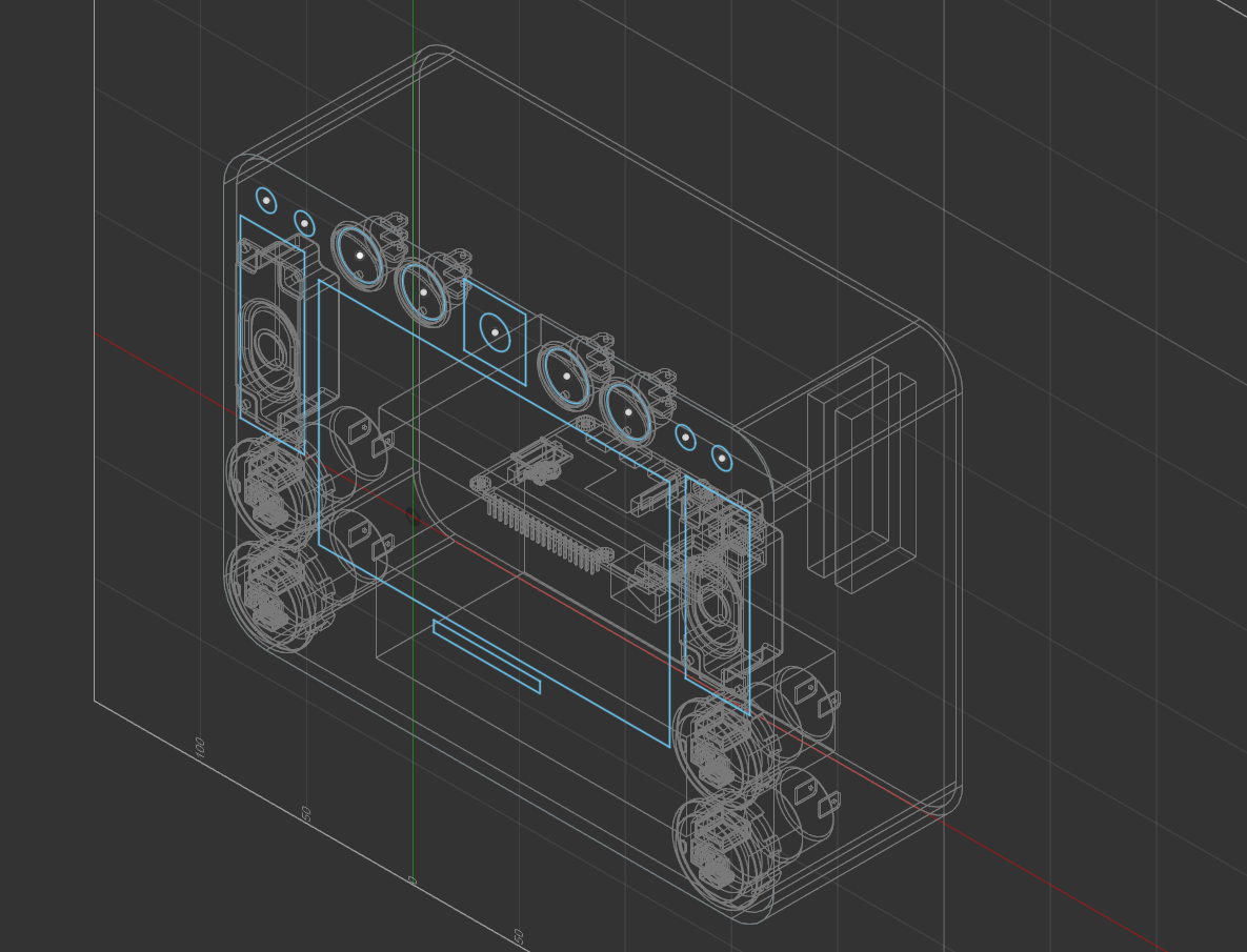
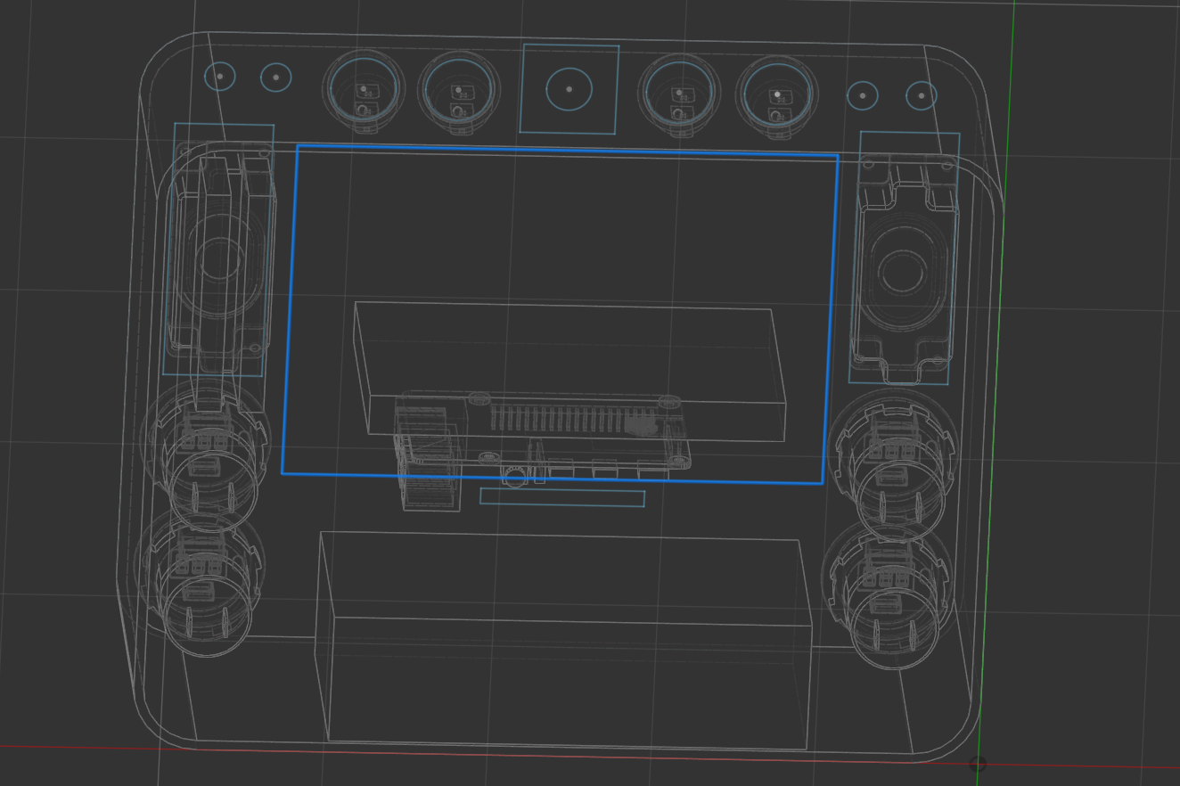
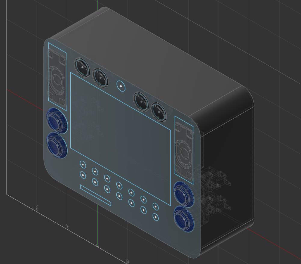
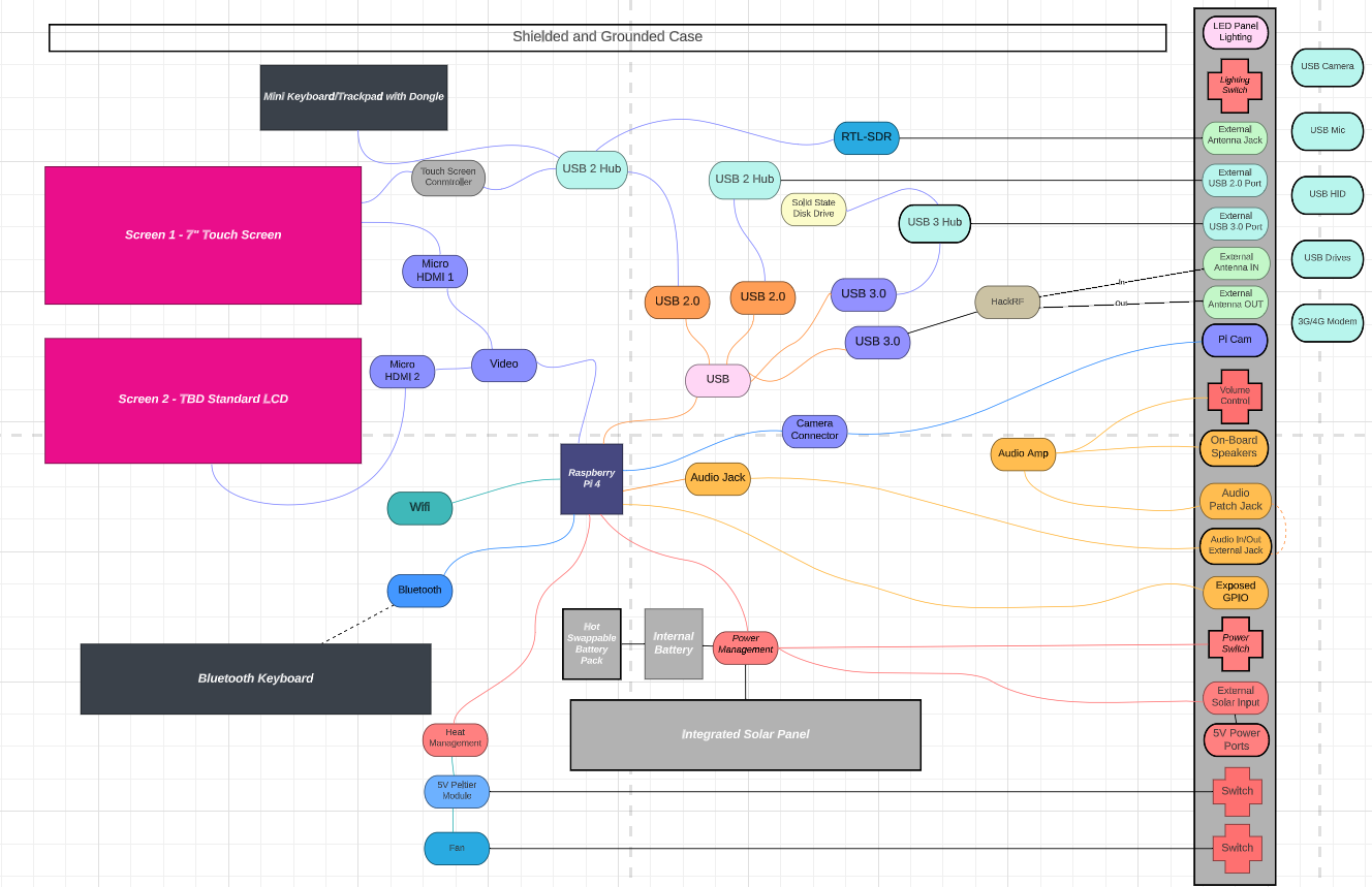
The basic functionality emulates a laptop with speakers, web cam, monitor, keyboard, mouse which to most is a familiar configuration. Add to that a HackRF One that can be used to both transmit (ultra low power) and receive frequencies from 10Mhz to 4 Ghz, an RTL-SDR to also receive radio transmissions but also to get ADS-B aircraft info and weather forecasts, also GPS for location, redundant UPS power, integrated solar panel, option to have multiple audio devices, ability to connect bluetooth devices, exposed GPIO and storage space for a Flipper Zero and lots of other stuffs.
On paper, the target spec/feature set looks like the following:
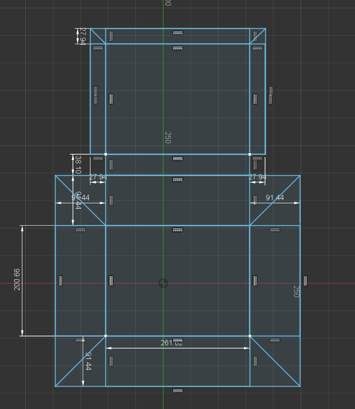
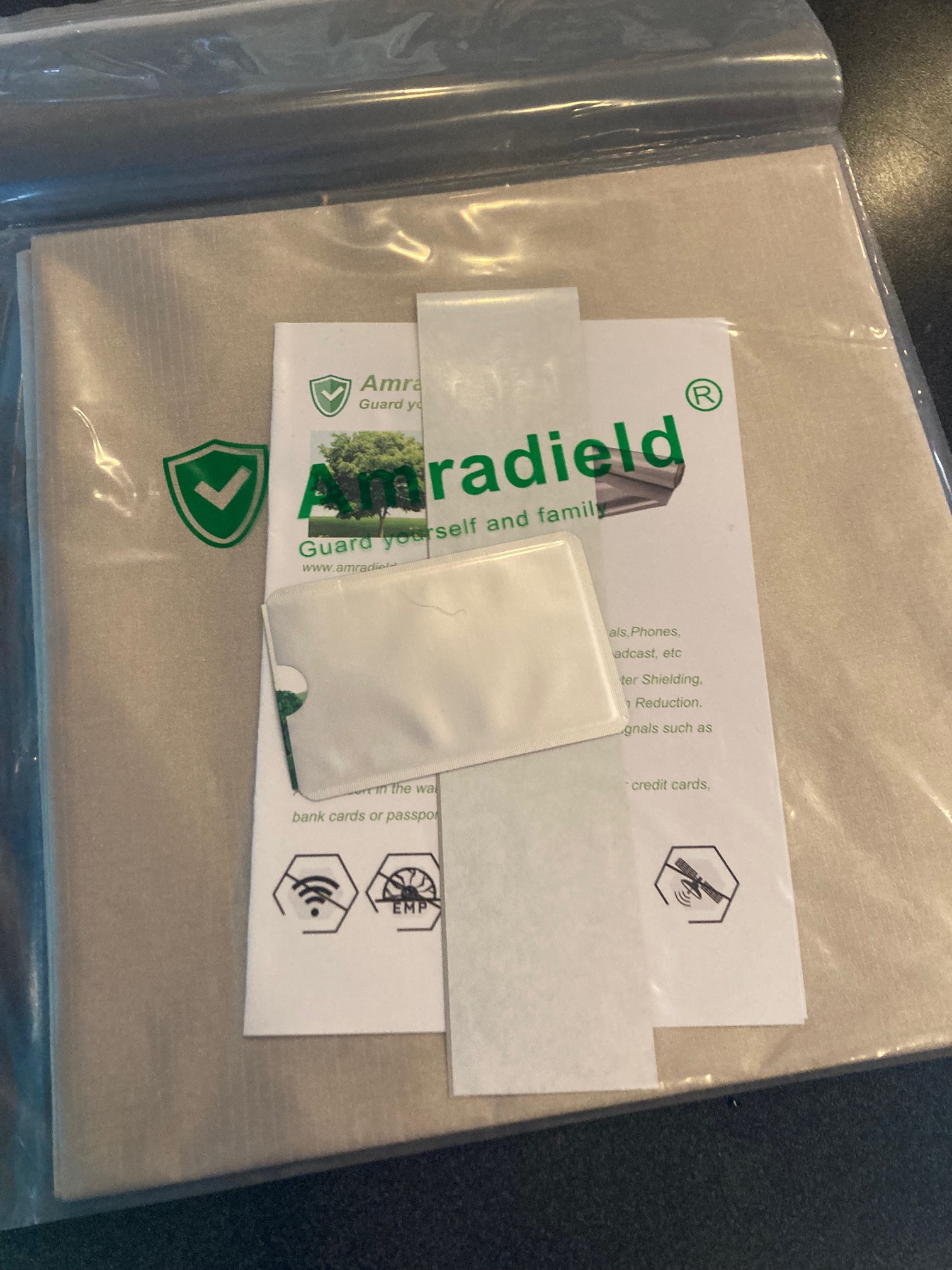
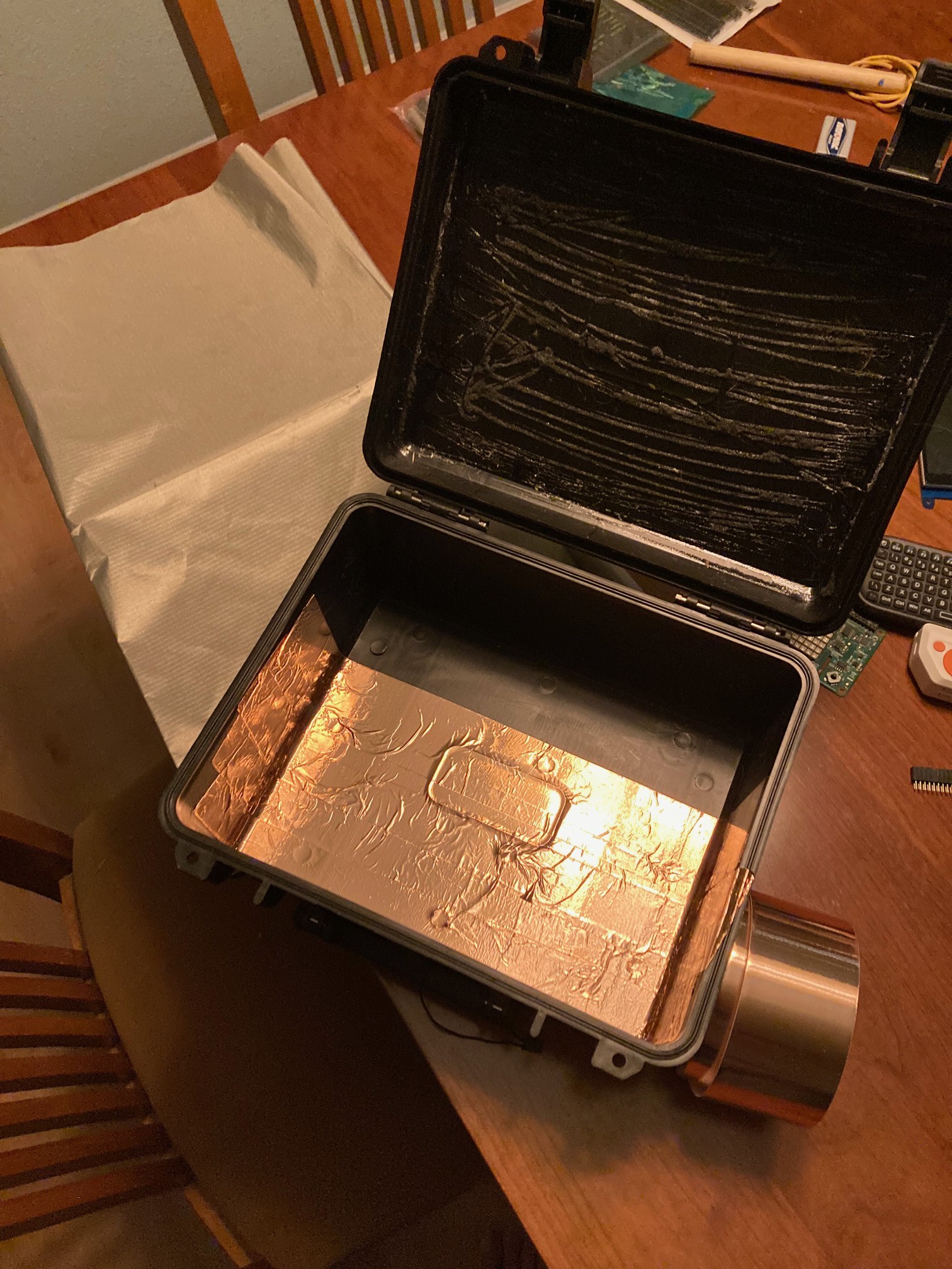
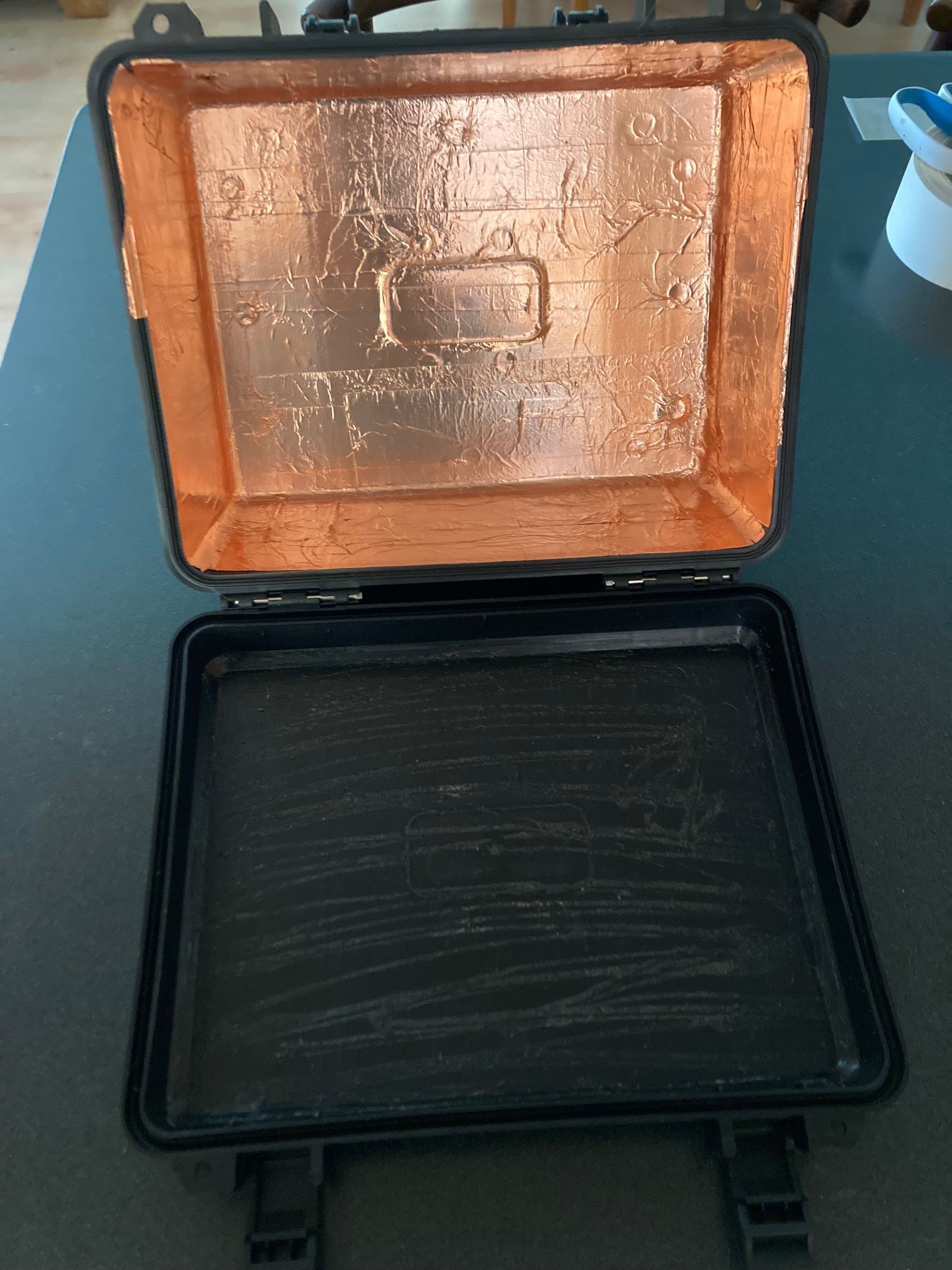
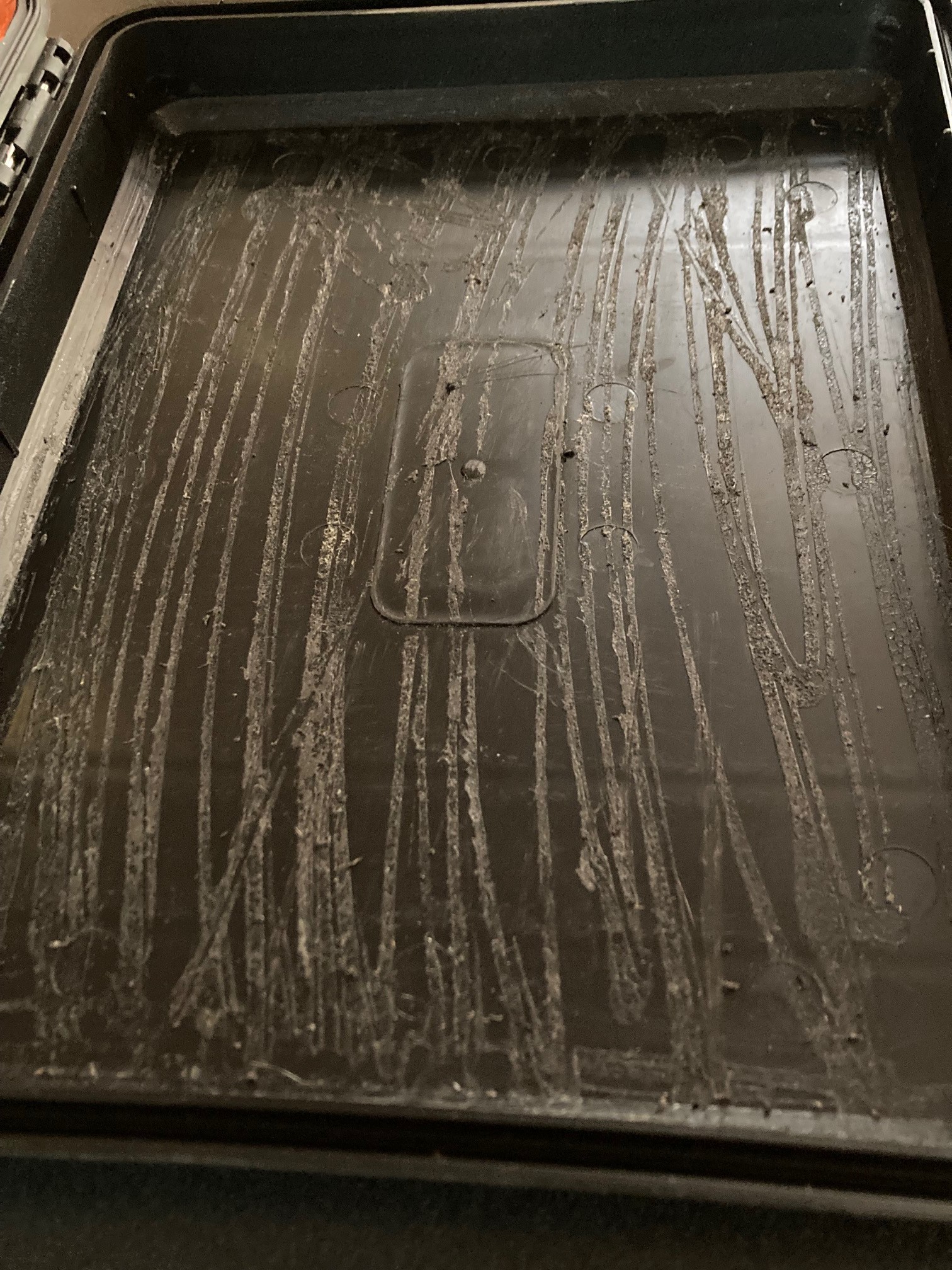
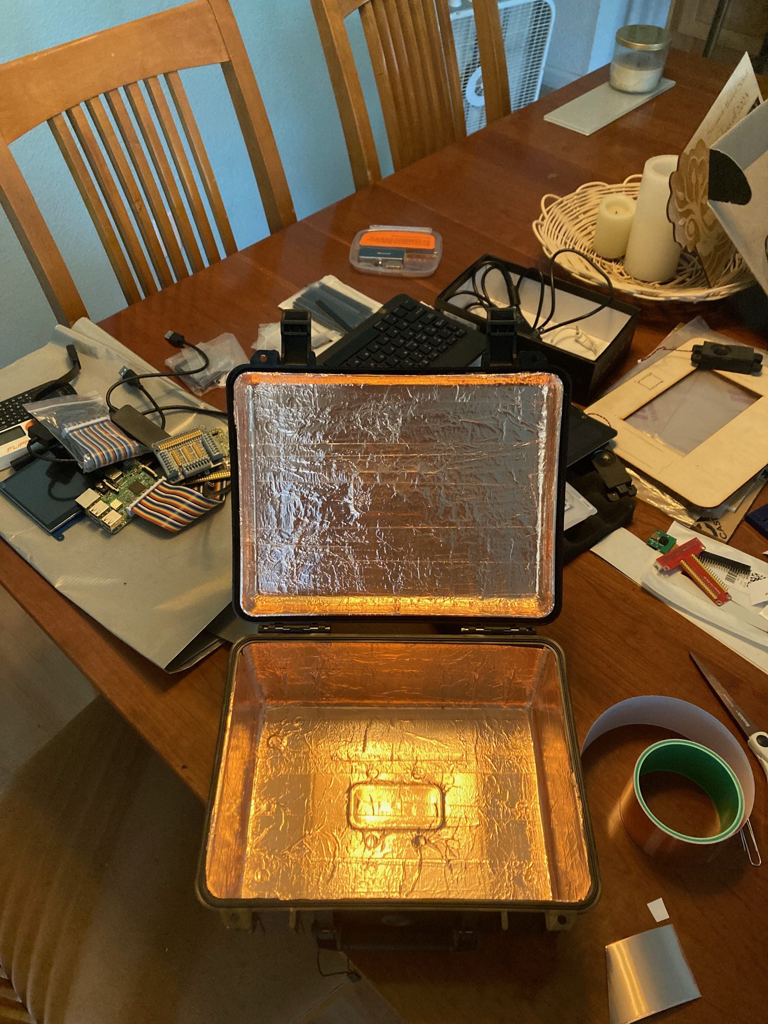
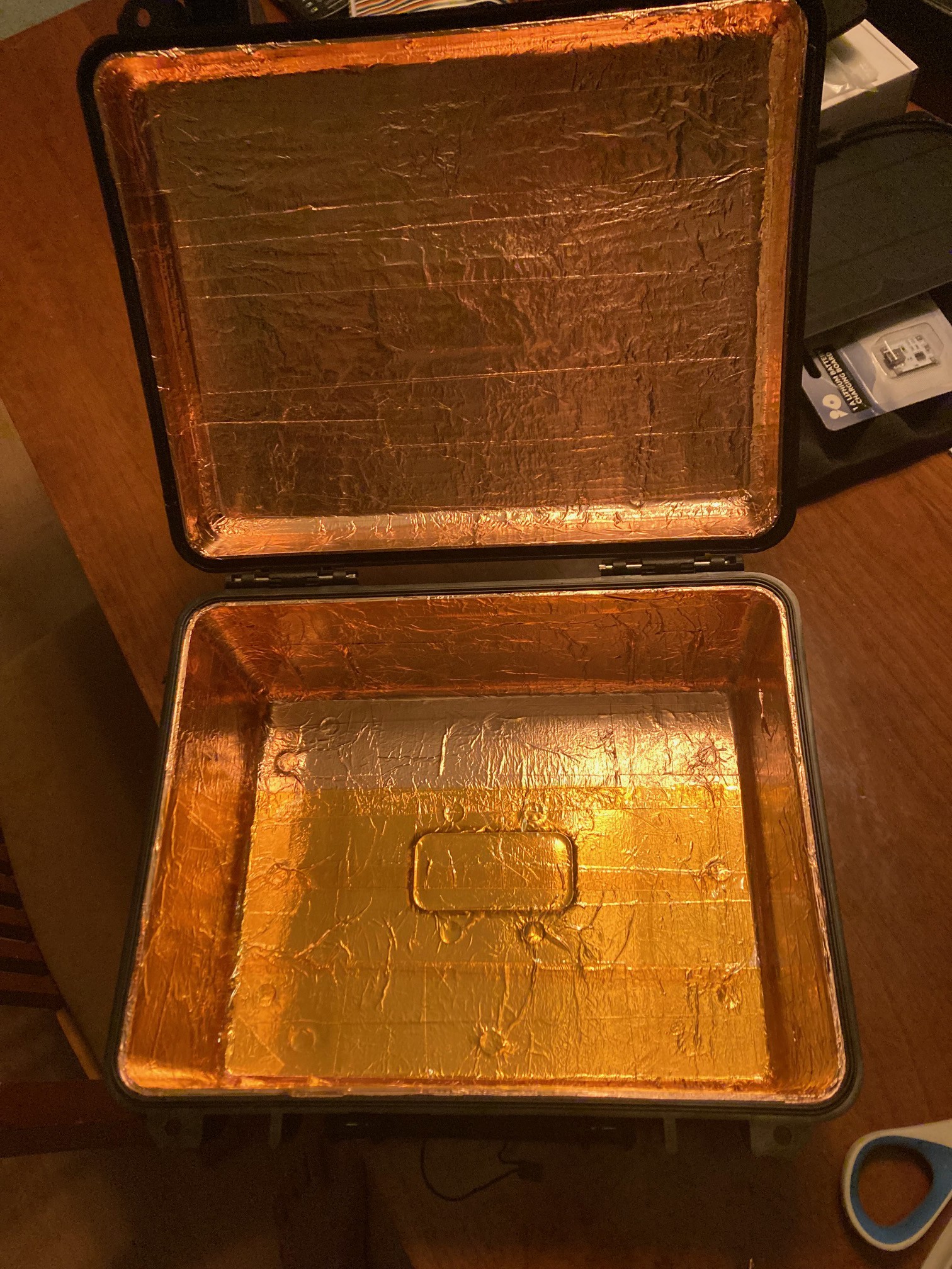
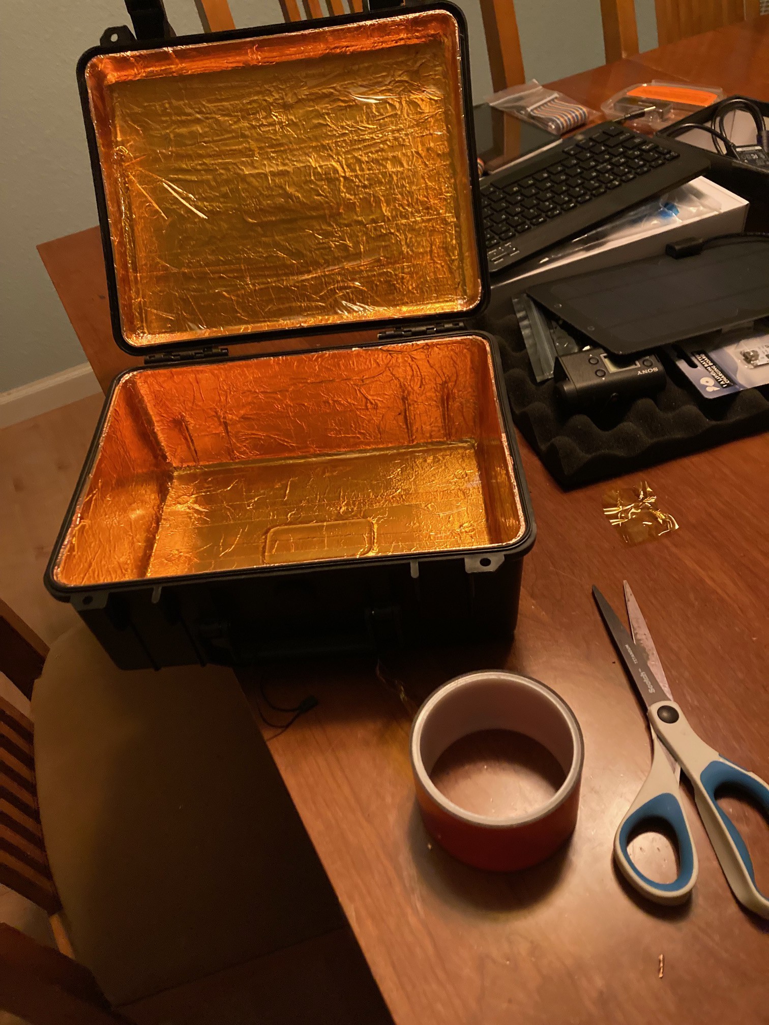
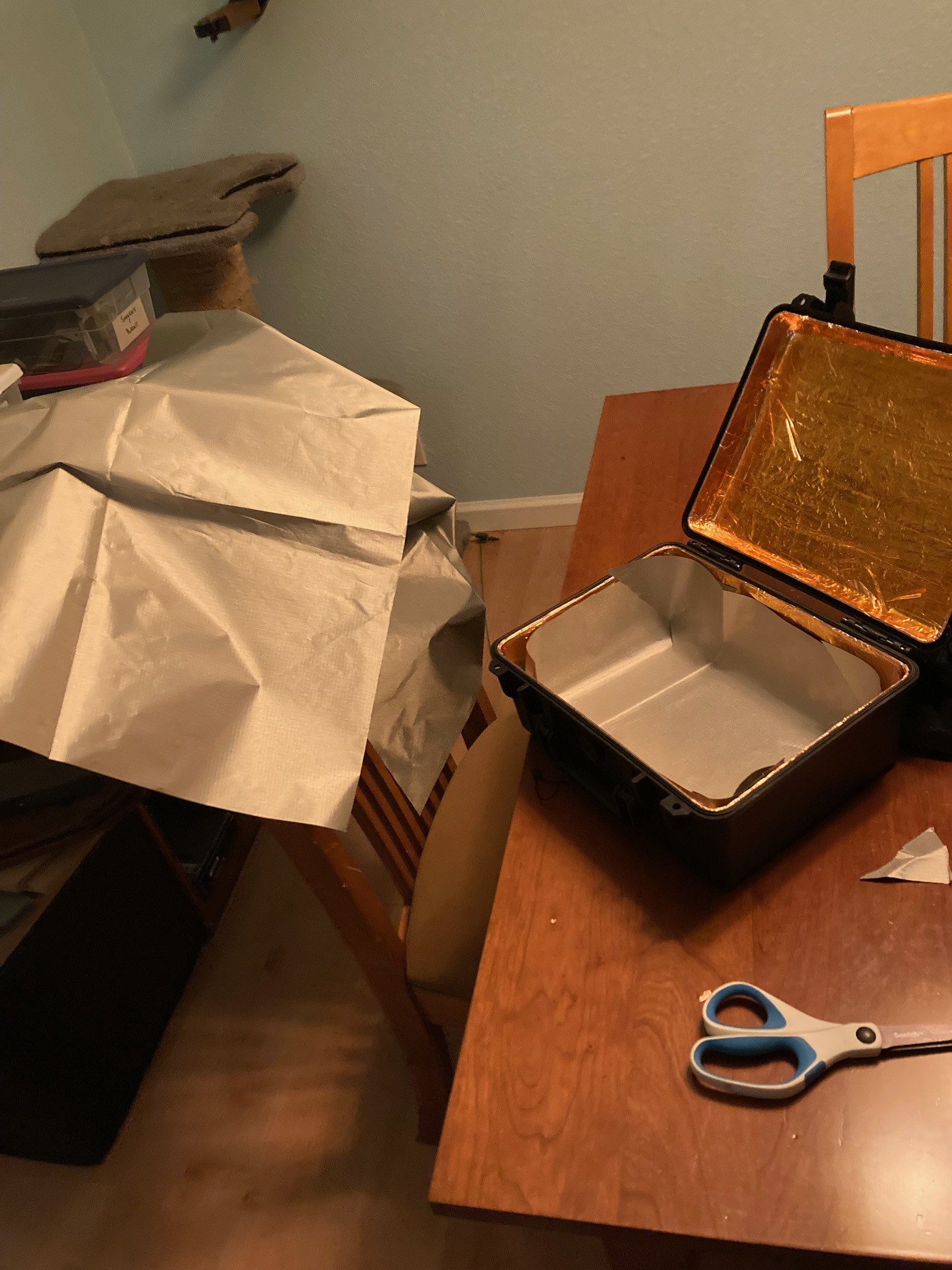
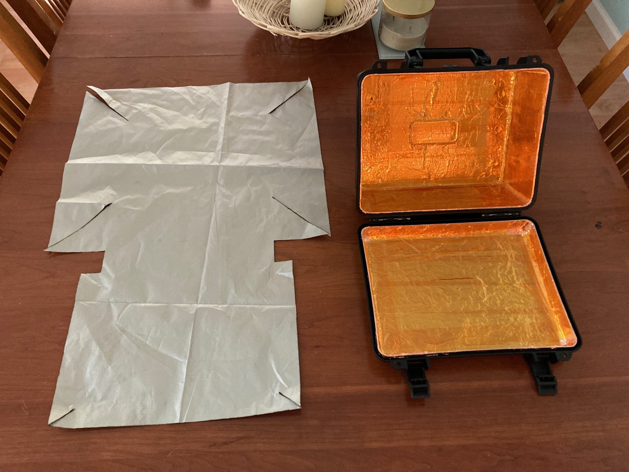
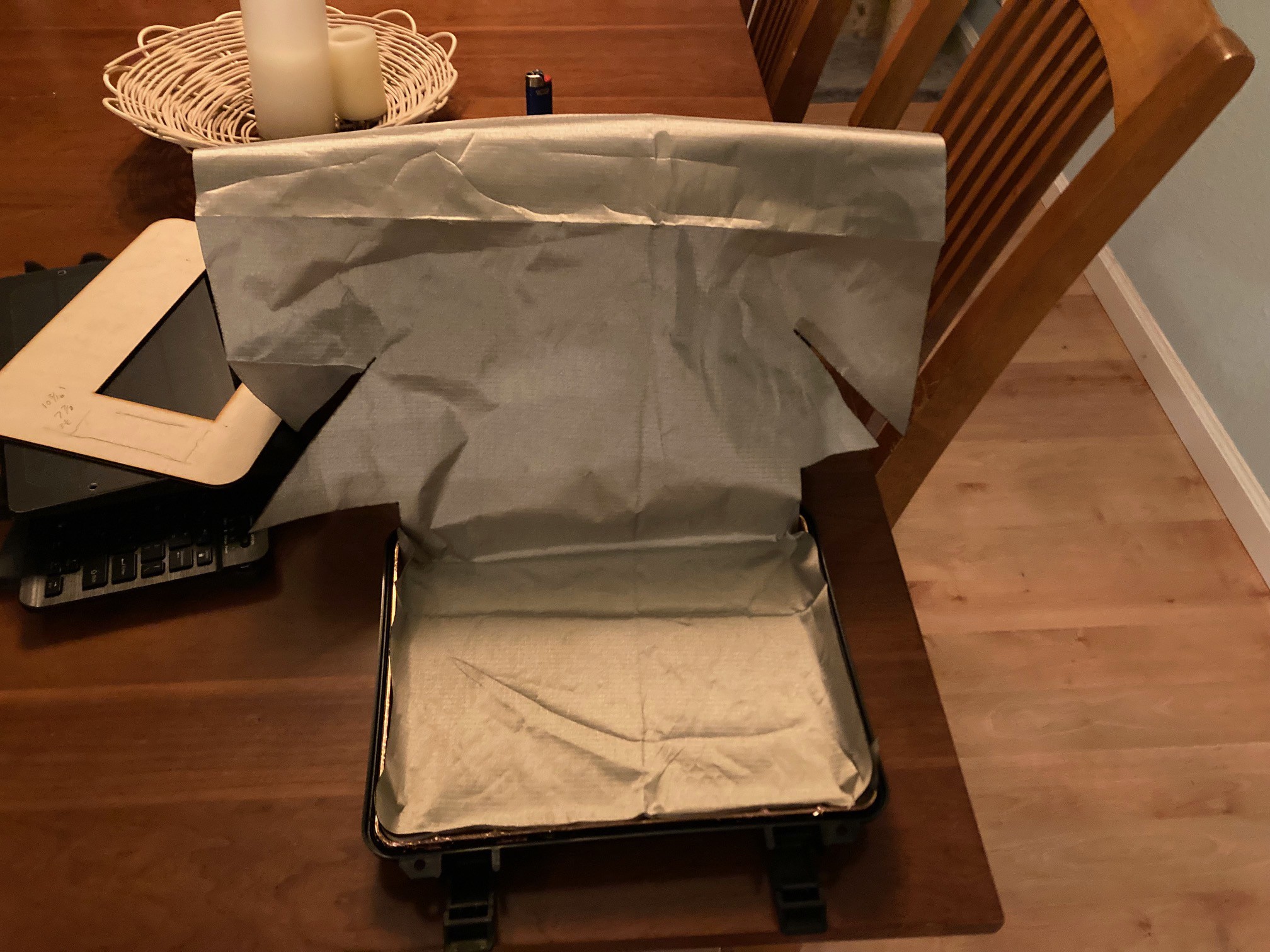
- RF Shielded (Farady) enclosure with the lid and body shielding electrically bonded to each other
- issue with wifi and other signals not being able to escape should not be an issue with the deck is in its Open configuration as the faraday enclosure would not be sealed
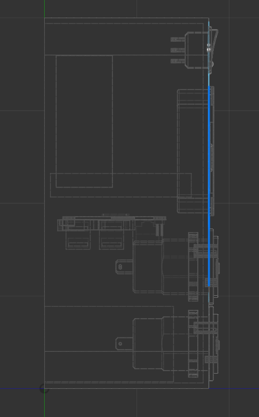
- Antenna ports will be on the front panel to avoid penetrating the case
- Pi 4 with 8G for highest performance
- 7" Capacitive multi-touch screen for keyboard free operation
- Second monitor, size TBD (stretch goal)
- Dual redundancy keyboard devices
- one slim line BT Qwerty keyboard
- one RF dongle mini keyboard with trackpad
- Wired mouse to minimize battery need/charge concerns for maximize lifespan
- Left and right speakers mounted on front panel and available through patch cable
- Stand alone audio amp available through front panel patch cable connection
- External audio source can be patched to Amp/Speakers on the front panel
- Redundant power sources, charge control and ability to run on a variety of power inputs
- integrated solar panel
- allow hot swappable USB battery packs
- internal core power bank
- battery monitoring with graceful power down
- a USB 2.0 hub and a USB 3 hub with ports extended to the front panel to allow for multiple devices, both internal and external
- HAT - Sense HAT, allows for the collection of telemetry data from inside the cyberdeck like air temp, humidity, air pressure, orientation, movement, etc.
- HAT - Speaker HAT, allows for direct connection of audio output to speakers with amplification, this would potentially be a switchable redundant audio system or a secondary
- Female - GPIO connector allowing for a male breakout to be plugged into the socket when needed, the breakout board is stored in the foam under the keyboard when not in use, listed below
- Male - GPIO Terminal Block Breakout Board Module for Raspberry Pi with Status LED
- Core Storage - Large size (256G >) SD
- Secondary SSD Mass Storage connected via USB 3
- eventually move to boot from SSD if stable
- Stored spare SD cards, 1 with OS, 1 blank
- Stored USB drive with archived files, stored in case foam under keyboard
- Stored Archived survival and cultural info
- Kiwix
- Wikipedia
- Survival Info
- Dictionary
- Medical Info
- Map Info
- Language archive/Interpreter
- Stored Archived OS builds and software in a way that the system can be restored to a functional state in the event of a catastrophic loss of data
- Stand Alone BT devices that will provide atmospheric monitoring and telemetry to the cyberdeck
- air temp
- air pressure
- air humidity
- light levels
- sound detection (lightning detection)
- magnetic field changes
- motion detection
- Locally...

 Tinfoil_Haberdashery
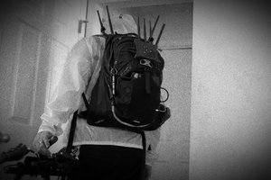
 Magic Robots
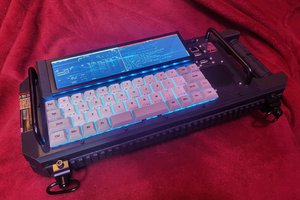
 Garra
Garra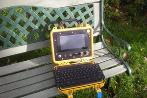
In conclusion, your project is ambitious and exciting, but it will require careful planning, dedication, and a methodical approach. https://www.screenmirroring.onl/teamviewer-review-best-app-for-screen-sharing/ If executed well, it could result in a unique and functional cyberdeck that combines cutting-edge technology with practical utility. Good luck with your project, and don't hesitate to seek advice and resources along the way!