Introduction
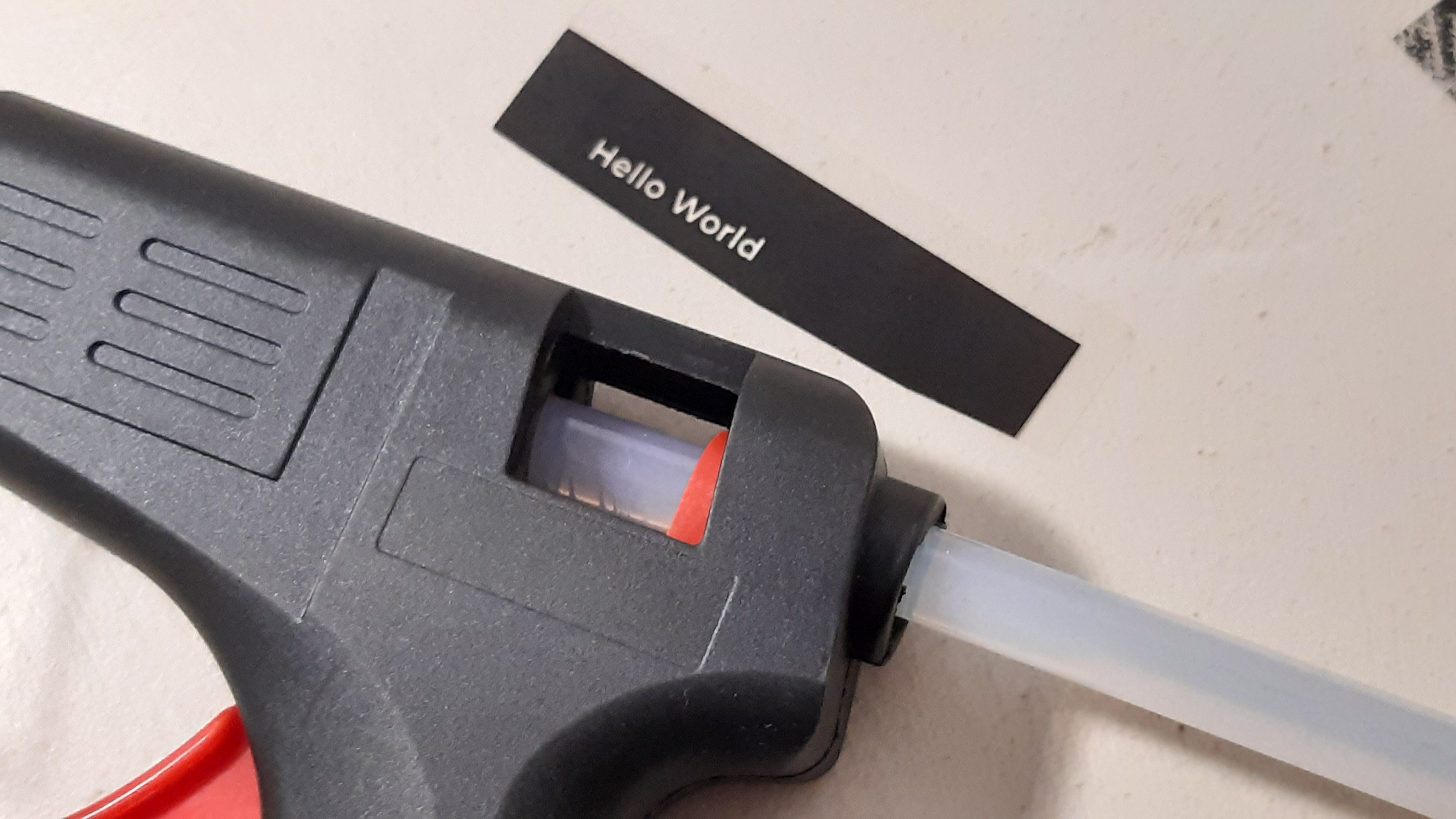
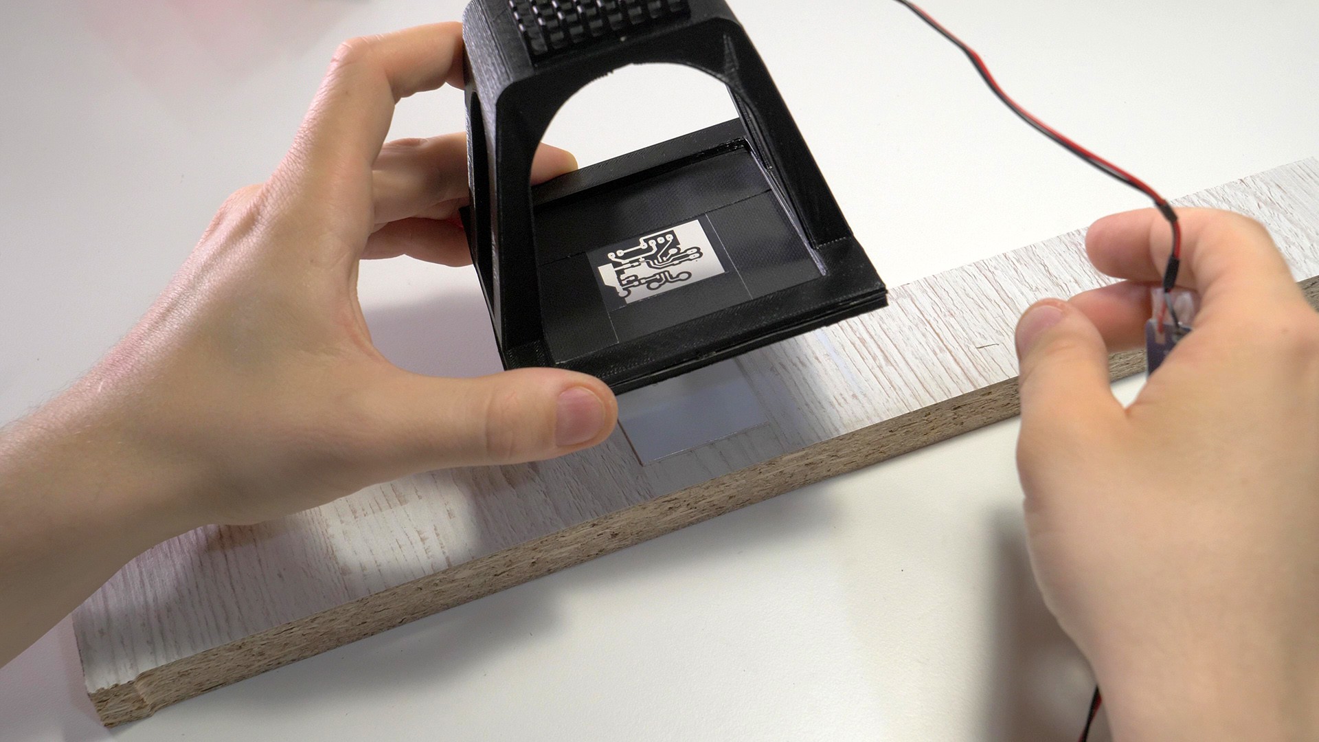
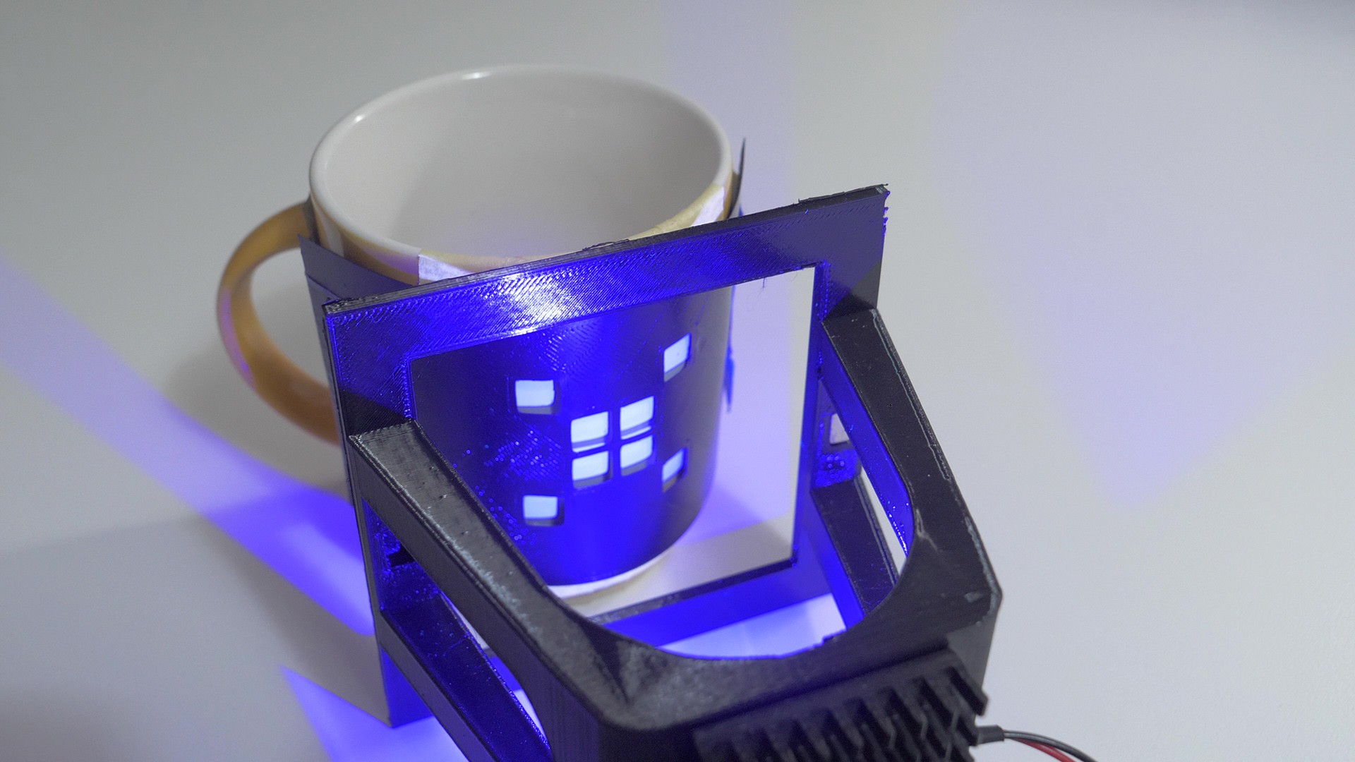
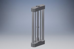
This tool currently has a form of a 3D-printed UV lamp holder with a magnetic frame (3d printed with magnets embedded) to hold inkjet- or laser-printed transparency films with exposure masks, or 3D printed masks for simpler designs and shapes.
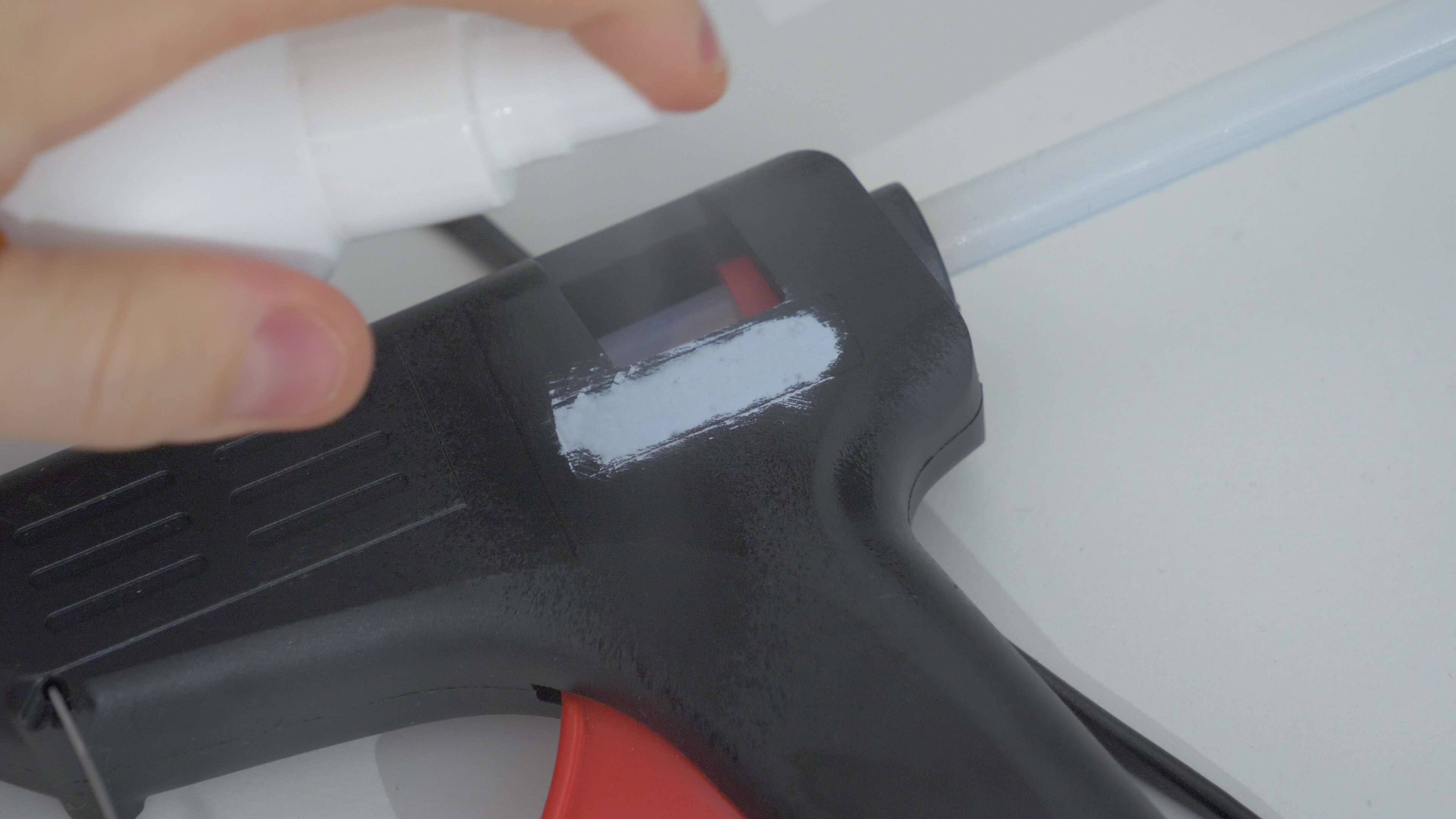
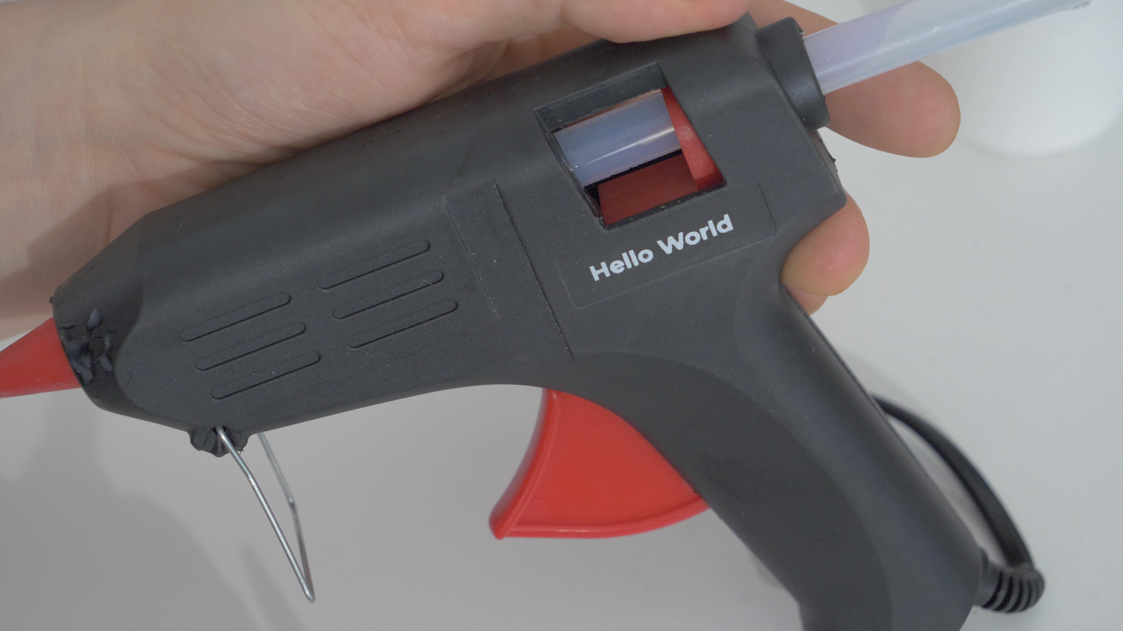
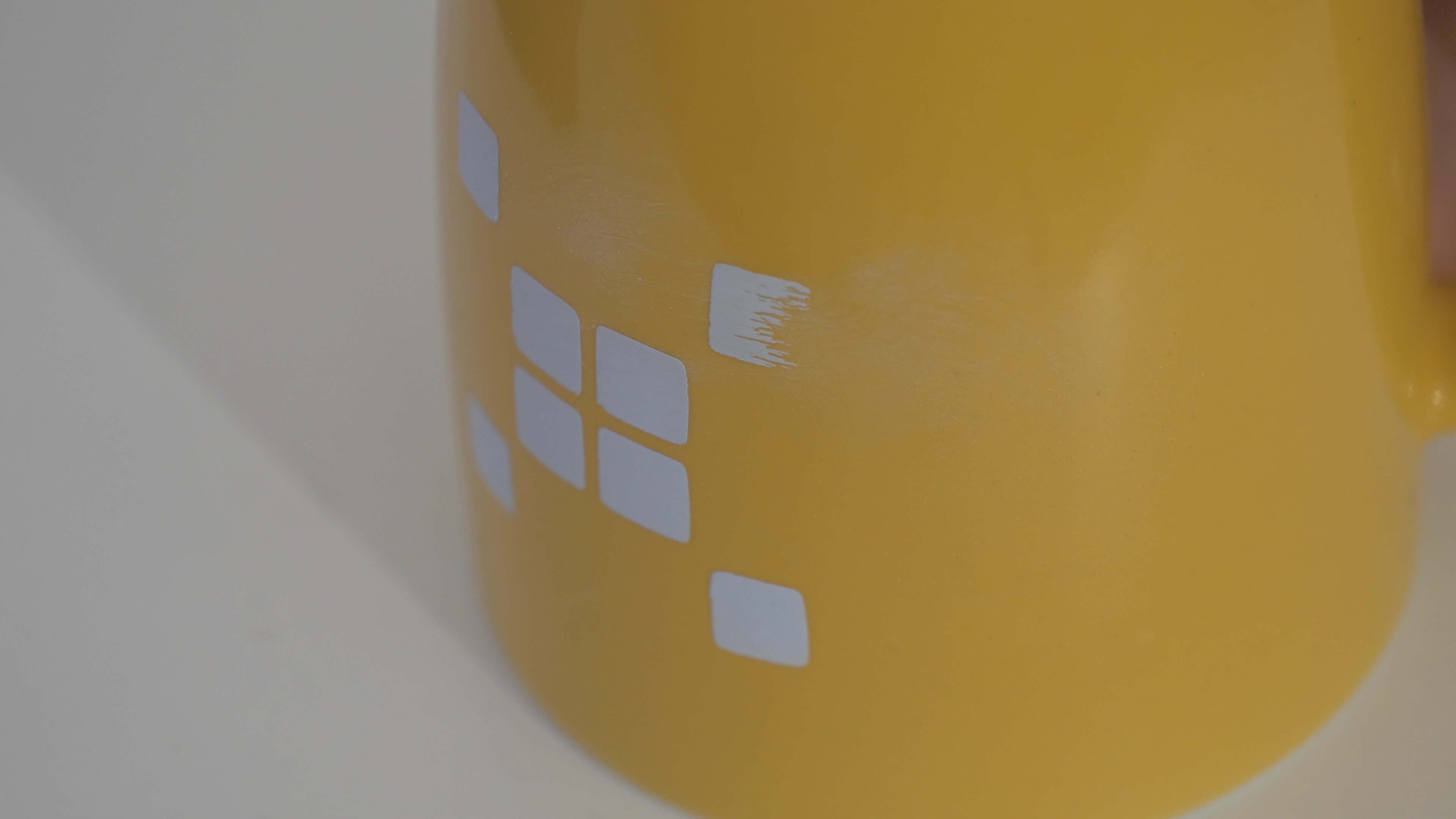
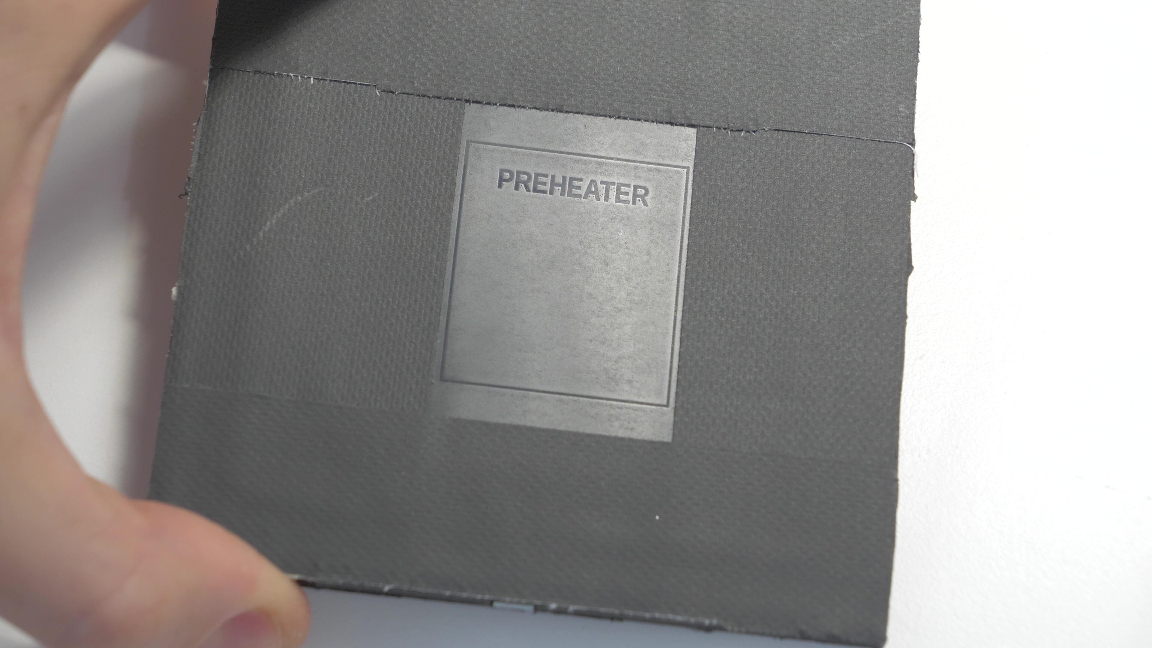
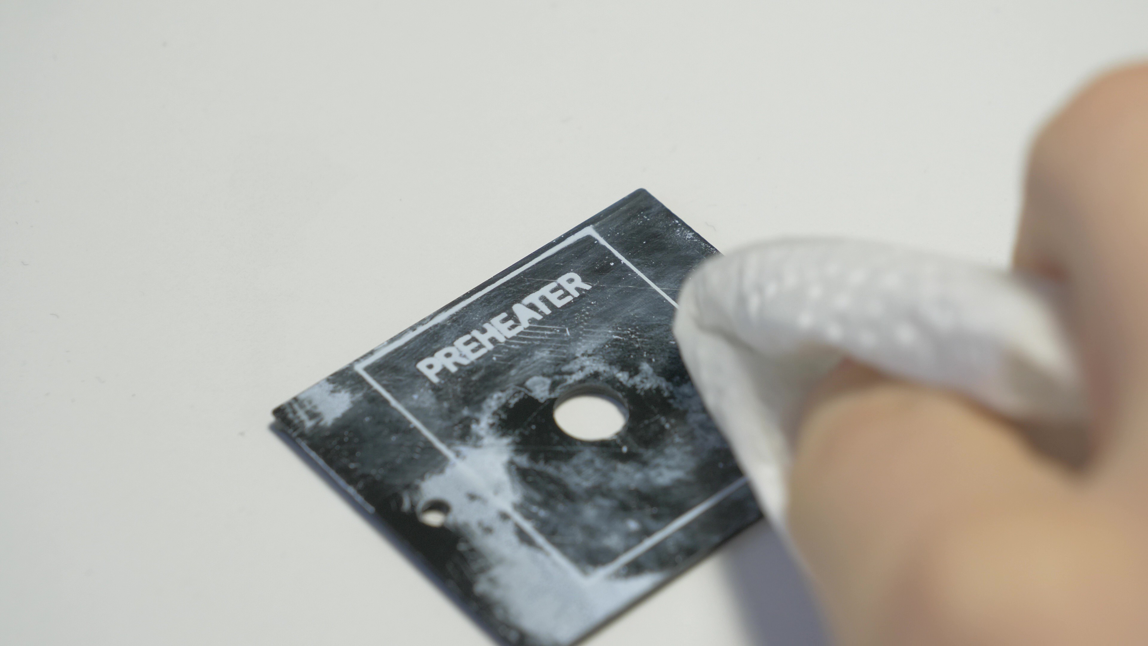
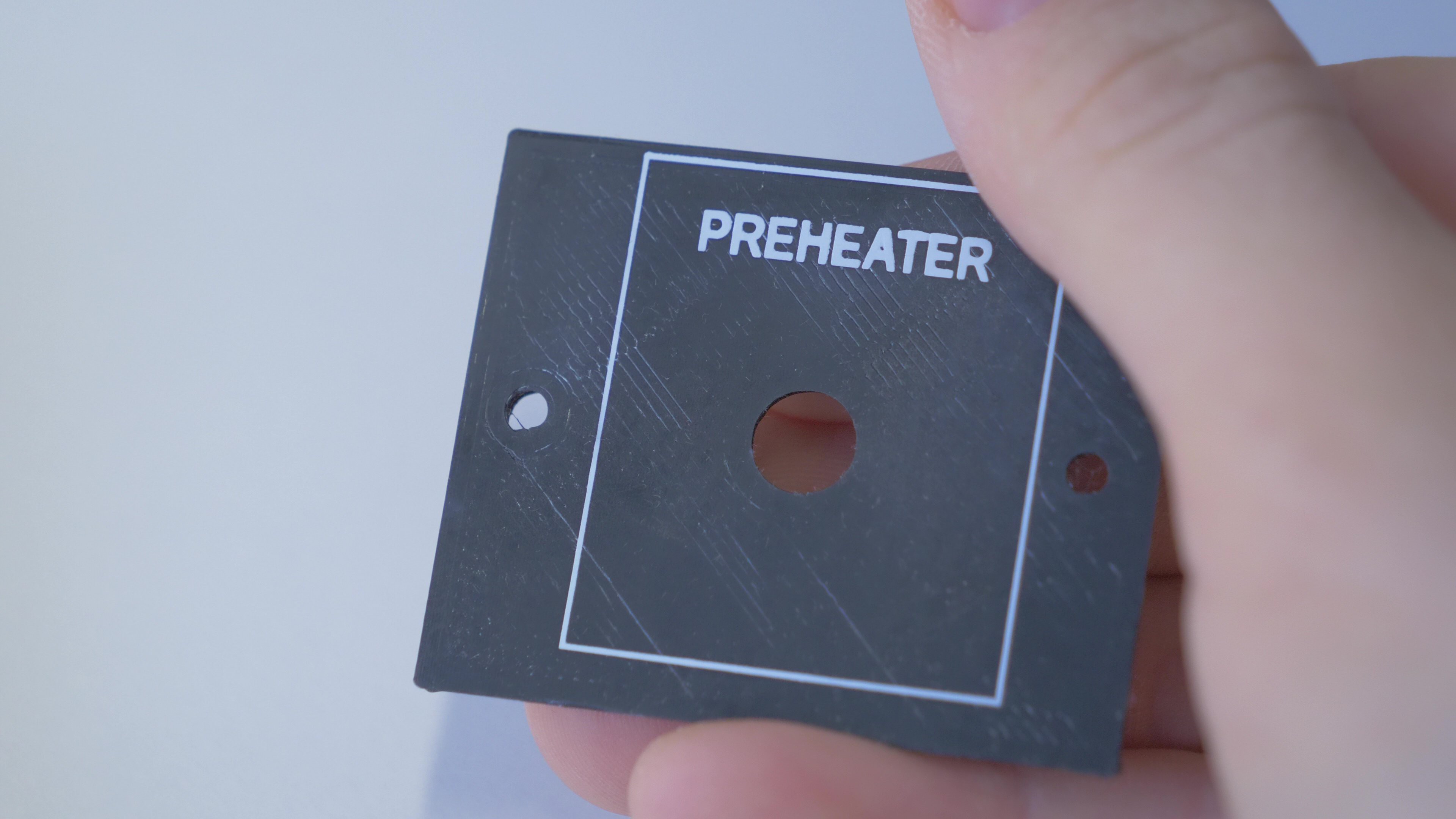
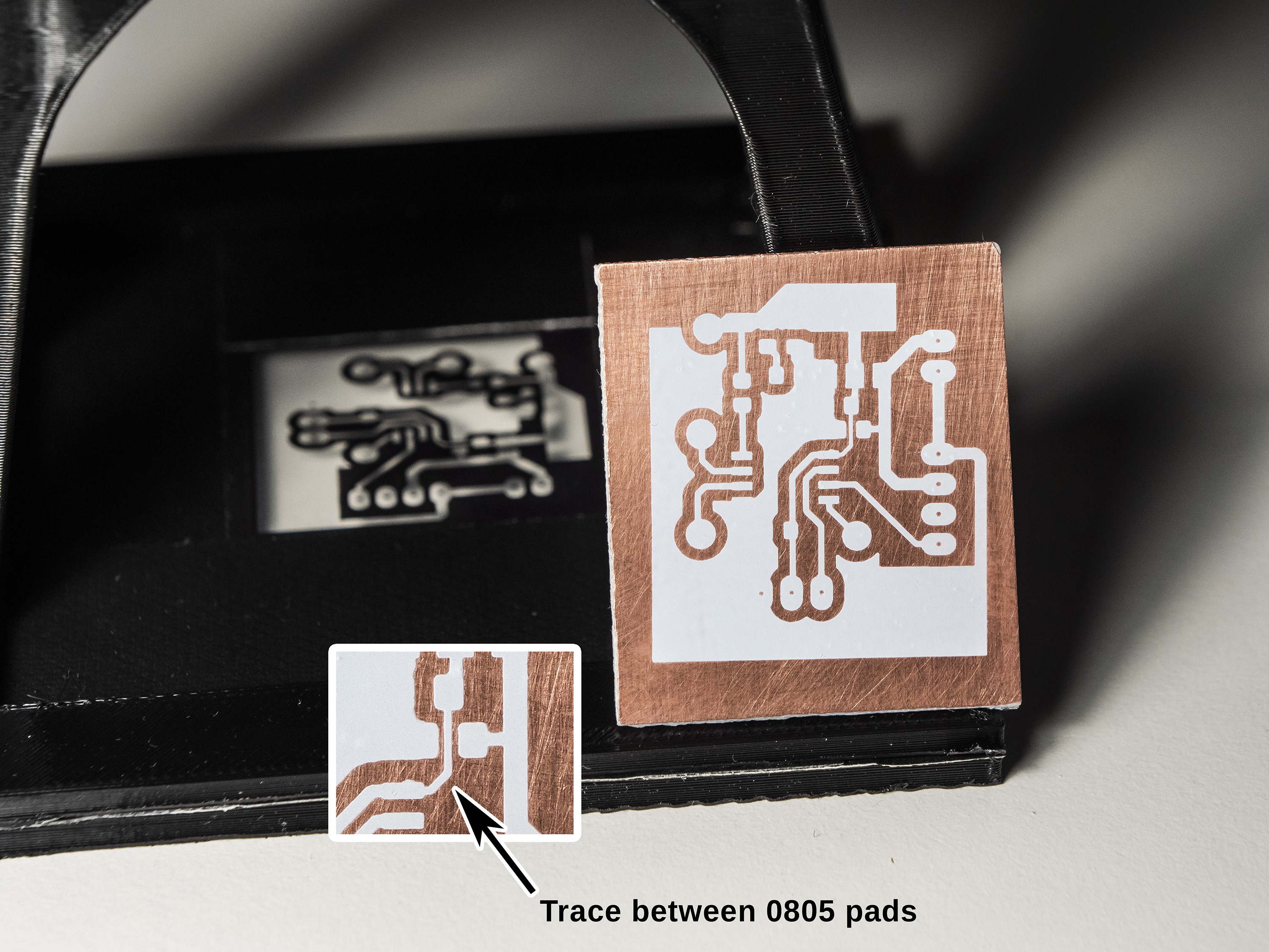
It can be used to print etching masks for PCB prototypes, print artwork on household objects, create item and panel markings (also on 3D prints, tested with PET-G material) and more.
It can be considered as a low-cost, easy to prepare alternative for screen printing or pad printing for one-off production or prototyping.
Advantages of this method
- No additional chemicals required to develop the artwork
- Works fine for prototypes and one-off projects - only few steps required, very low initial cost
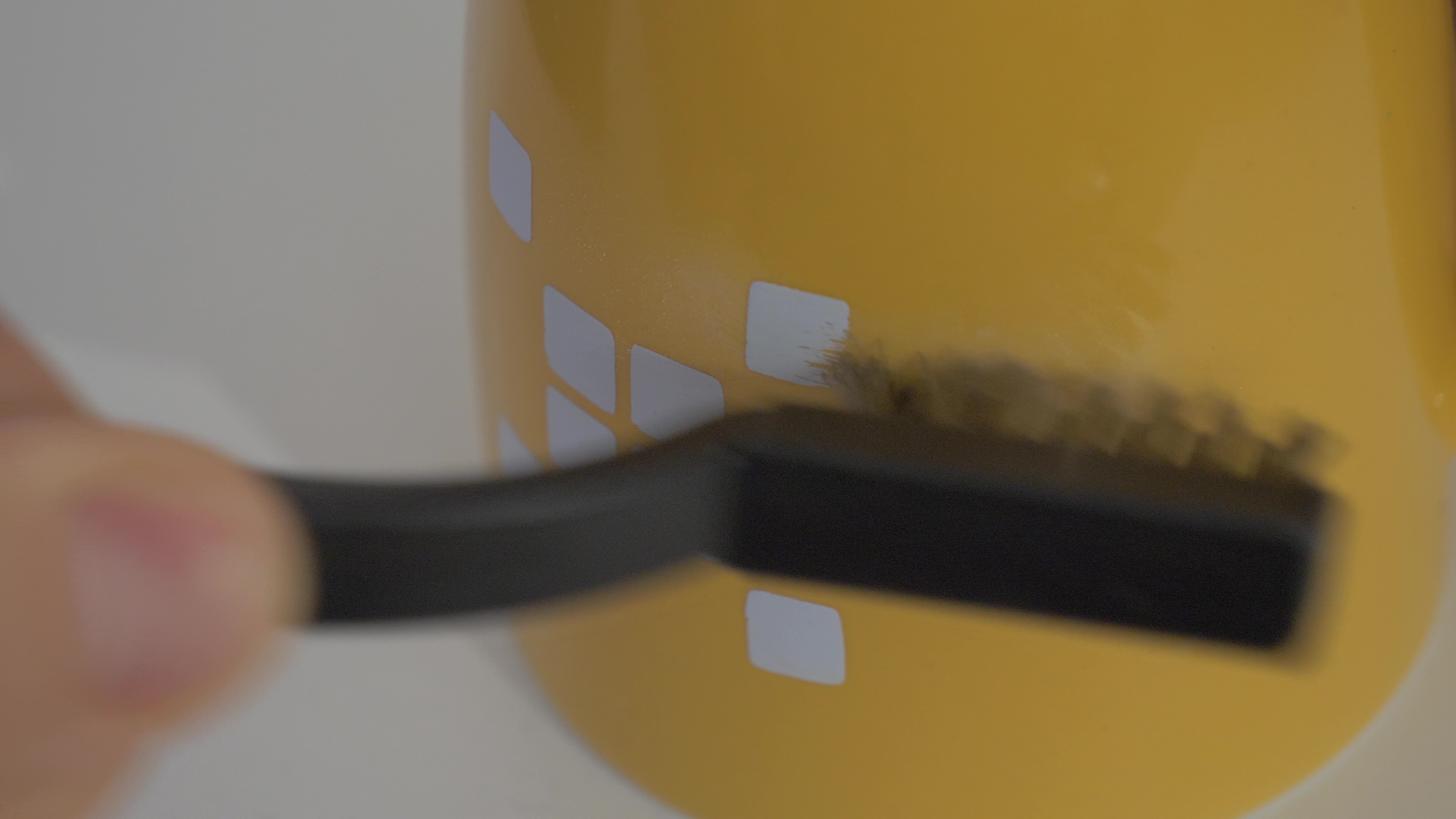
- Ability to print on uneven/curved surfaces
- Multitude of uses: etching masks for PCBs, printing on objects, item and panel markings
- Contact-less exposure
Challenges
- How to get a powerful and even UV light to retain sharp edges of artwork
- Setting proper exposure time
- Scaling the project up for larger objects
- Replacing static UV mask with LCD (WIP)
How does this process work
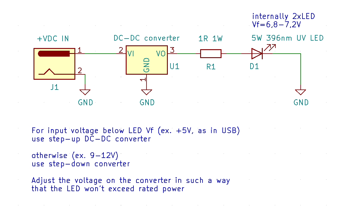
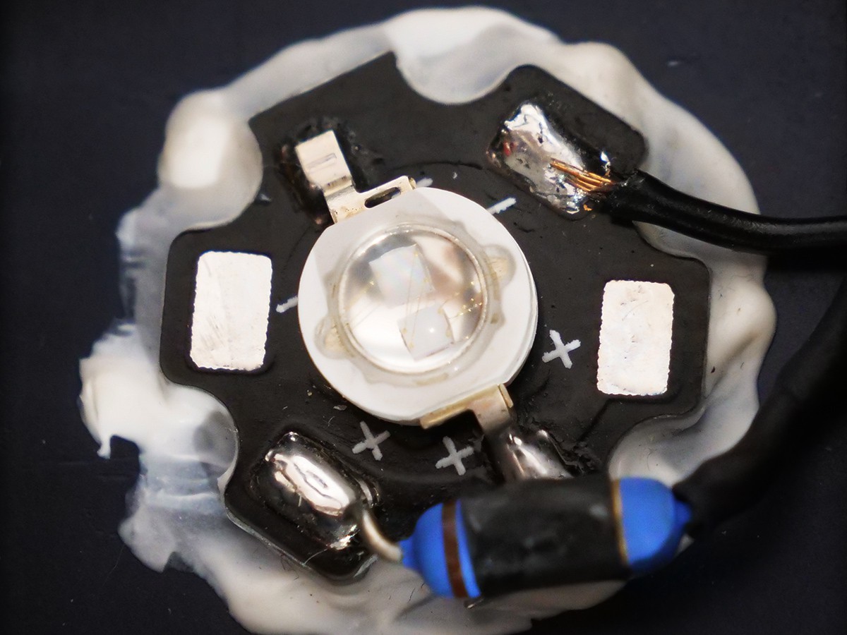
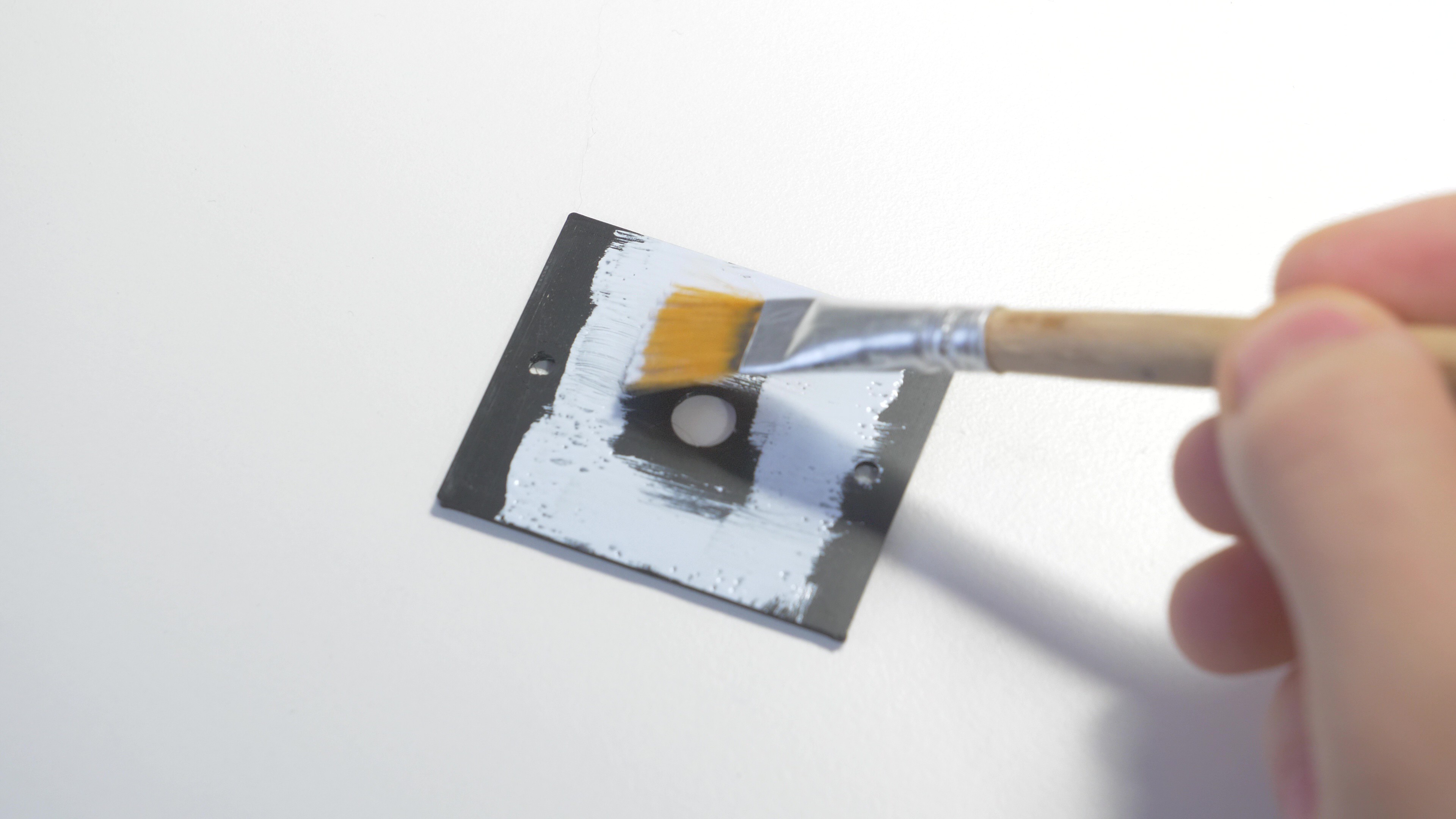
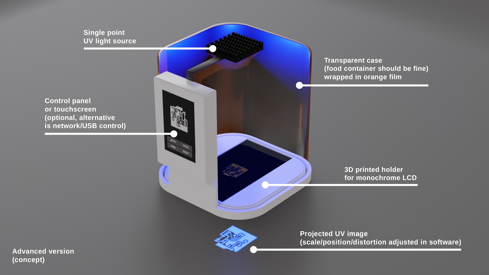
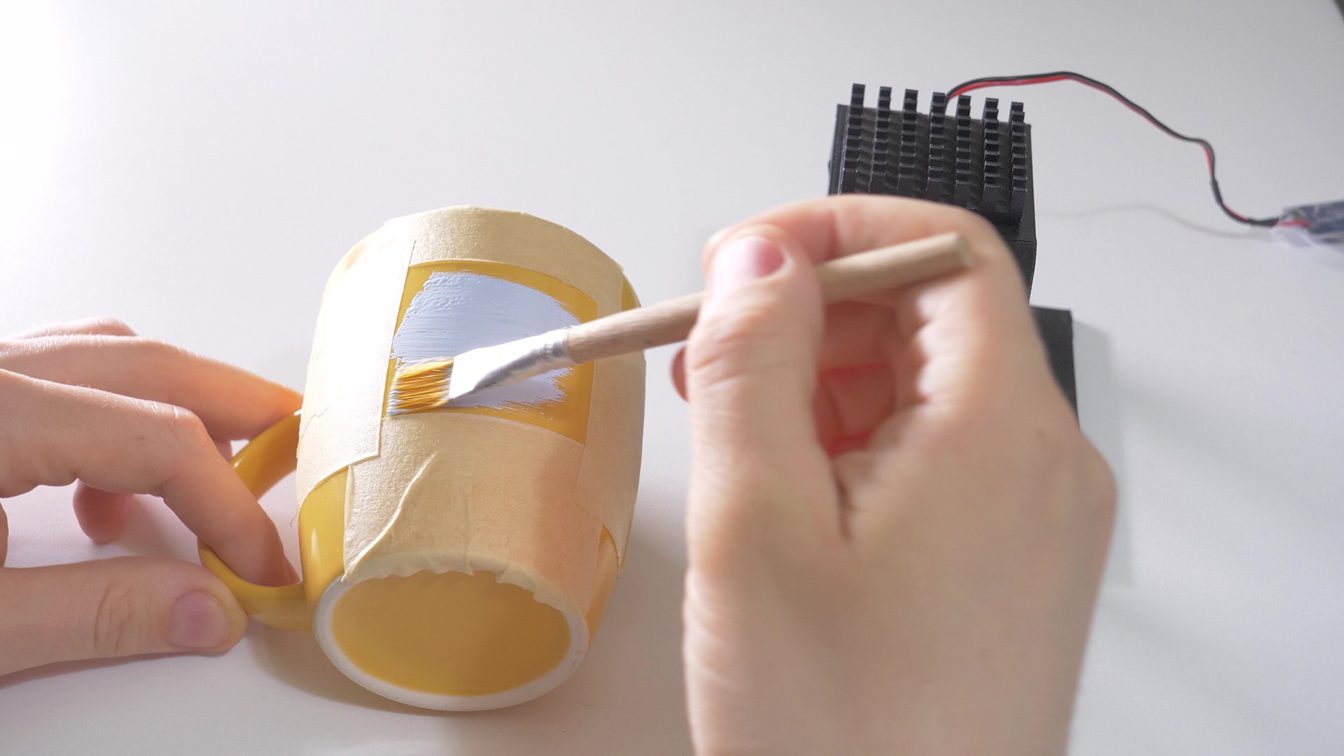
The exposure process is contactless, ie. the mask is not touching the object that is being printed on. Object needs to be covered with inexpensive UV-curable soldermask or another type of UV paint with a brush or rubber roller. Mask is rised few milimiters so it doesn't touch the paint. UV light comes from a single point, a power LED placed directly in the center of the holder, and such type of lighting doesn't create too much optical distortion and retains sharp edges of the artwork.
Future perspectives
In current stage this tool uses either a transparency film or 3D-printed stencil as UV mask. Future improvements may include replacing the printed mask with a monochrome LCD, which would make the print preparation process entirely digital, using optical zoom to scale the printed artwork, automatically distorting the mask to accomodate for curved objects.


 setCREATE
 Padfoot
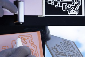
 paul
paul
The resolution of a monochrome LCD can vary depending on the specific model and manufacturer. https://www.survey.onl/caseys-feedback/ It is typically measured in pixels, such as 128x64 or 192x128.