 Fangzheng Liu
System description
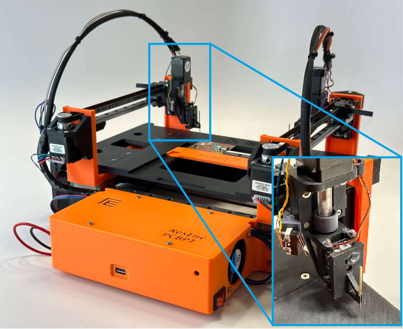
- Mechanical system (CircuitScout machine):
The CircuitScout machine is a CNC machine (35cm x 33cm x 18cm) that features a dual-probe system designed for precise robotic probing of specific pads on PCBs. The PCB to be tested is positioned and secured on the machine platform. Stepper motors are employed for precise XY-axis movement, while compact linear servos control the Z-axis motion of the two probes. The 3D files that are required to be printed can be found below, and the assembled modelization can be found on onshape.
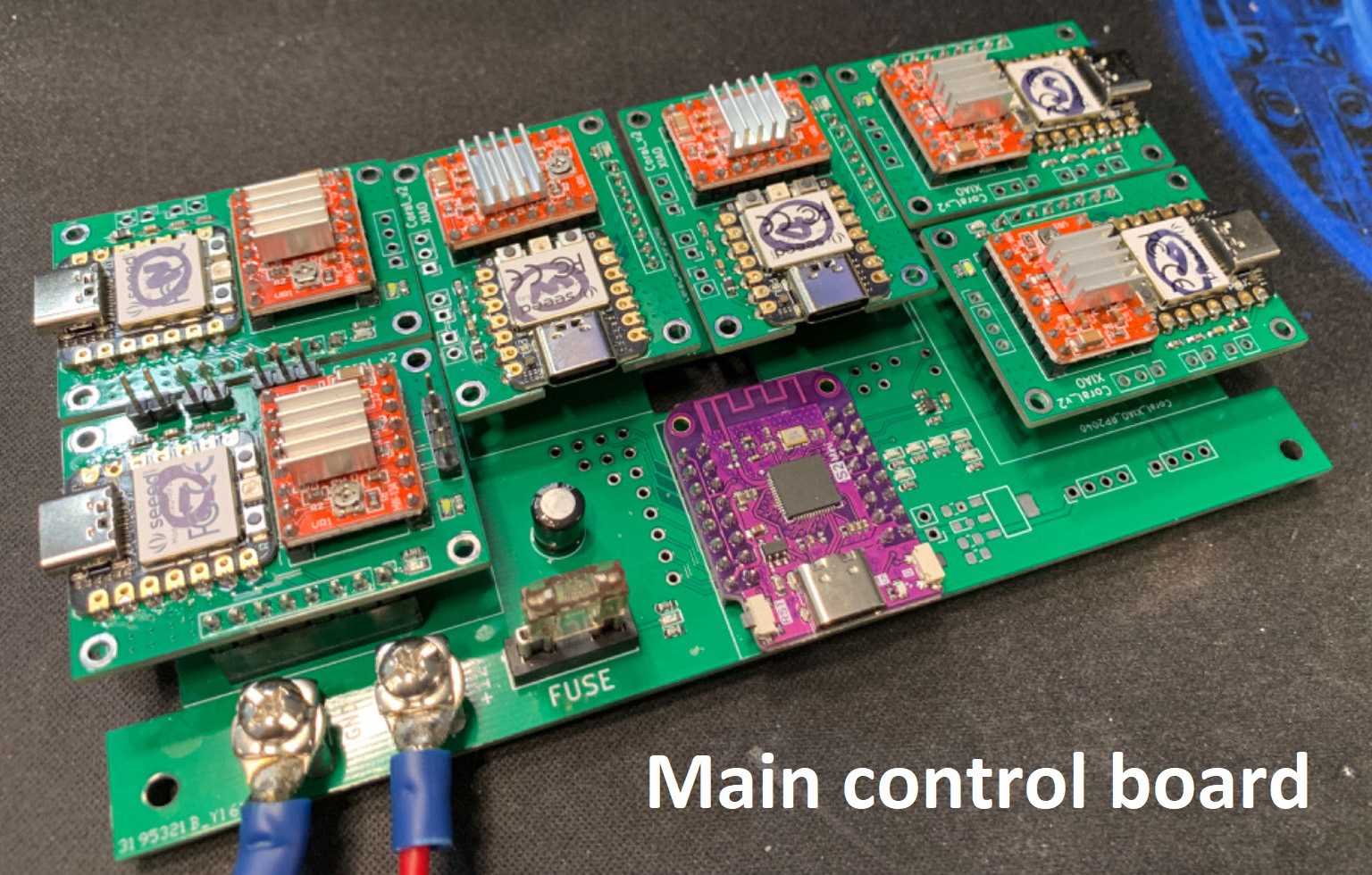
- Control electronics:
The machine's controlling electronics are illustrated below, consisting of an ESP32S2 module that is connected with six separate stepper motor/servo control modules, which we named the “Coral” module. Each Coral module is a fusion of a Seeed XIAO RP2040 module and an A4988 stepper motor controller module that can control both a stepper motor and a servo.

These Coral modules are connected to an ESP32S2 module, itself is connected to a computer where the GUI server is running. The GUI communicates with the ESP32S2 module through Serial. The GUI sends the coordinates of the desired pads to be probed and receives data on the status of each Coral module. All Coral modules are connected to the ESP32 through an I2C bus. The ESP32 can also use a wireless connection between the machine and the GUI.
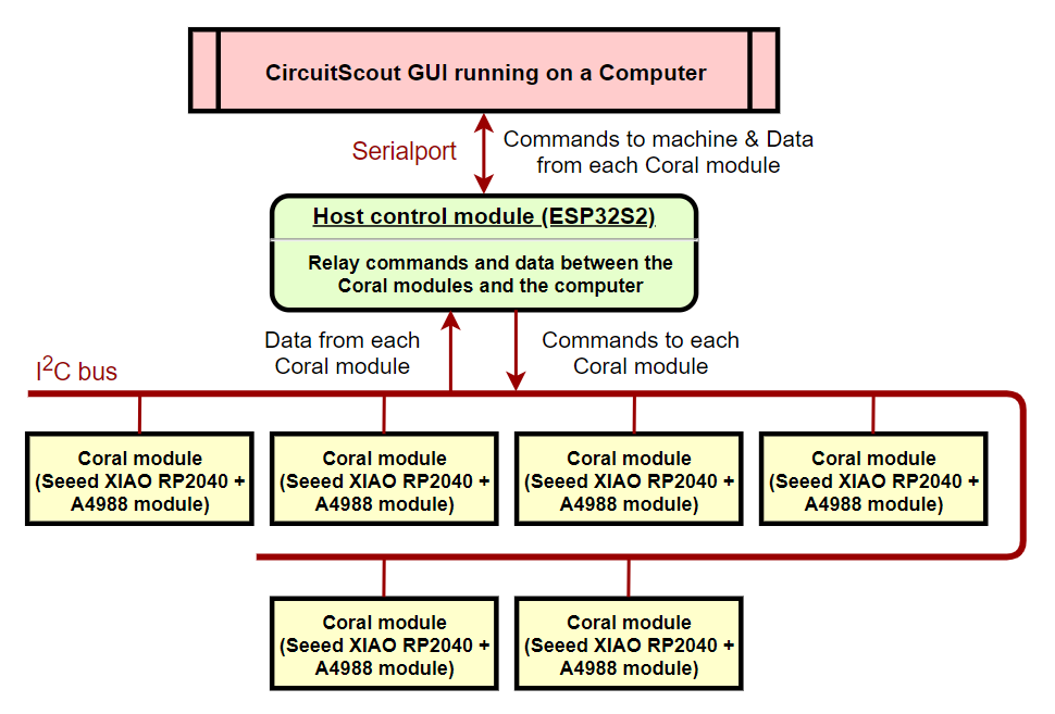
The CircuitScout system is compatible with KiCAD design files. After users select desired signals to be measured from the schematic in the GUI, the system will automatically select proper pads for the corresponding signals and control the machine to probe the pads. With the help of CircuitScout, all the user need to do is select signals from the schematic and check the output.
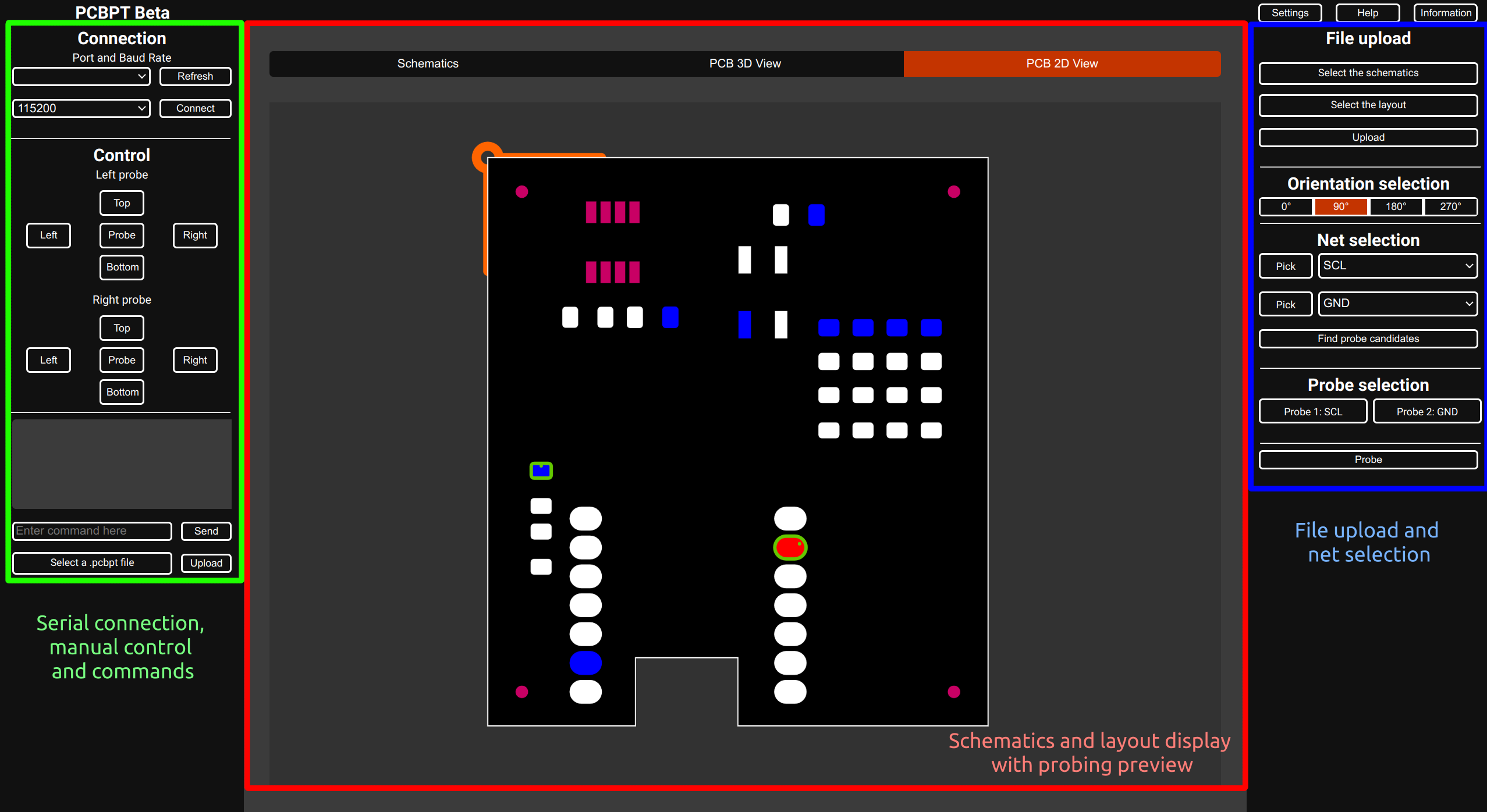
- Graphical User Interface:
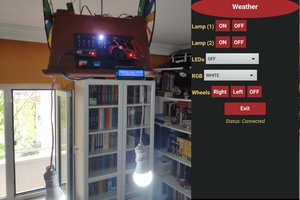
The GUI is hosted by a Python server that uses Flask-SocketIO as the backend. Any device on the same network can access and use it. The interface is divided into three sections: on the left, the user can connect to one or multiple machines by selecting the port and the baud rate. Since the main board receives commands through serial, any serial interface, such as the Arduino IDE, can be used to send commands. Commands can be written and sent using an input, and a console output displays the response of the device. A .pcbpt text file containing multiple commands can be uploaded if needed, and each command is executed at a fixed delay (1 second by default). The delay can be set in the file using SETDELAY n, with n being the number of milliseconds to wait after each command.
In the center, the board’s schematics and a 2D and 3D view of the layout are displayed. These drawings can be interacted with to select the desired nets to probe. The pads selected to be probed are highlighted in green, with a dot representing the position the probe will aim for.
On the right, users can upload their project’s Kicad files. These files are then hosted on the server side and the session of the user is preserved between page refreshes. The orientation of the board can be set to match how the physical board is placed on the device. Some selectors allow you to choose which net to probe, and "Pick" buttons allow you to select the nets directly from the schematics or the layout by clicking on the wires or the pads. Pressing "Find candidates" will select the best pads to probe from the selected nets by maximizing the distance between the probes. Two buttons allow the direct selection of the pads to probe, bypassing the automatic selection. Finally, a "Probe" button sends the probe command to the device.
All the relevant files can be found on the project's GitHub organization.
Future works:
A lot more work needs to be done to reach a product-like state, but the current priorities are the following:
- Improving the interactivity of the layout and schematics displays
- Redesign the probes to allow more retractation during movements:...
Read more »


 kutluhan_aktar

 hylke44
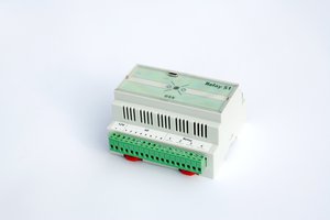
 strange.rand
I'm super interested in implementing this in the lab I work in, but none of the boards we'd be testing were built in KiCad. Is there a list of serial commands that could be used to manually create "toolpaths" for the probes?