Step 1: Power Amplifier Conceptual Framework
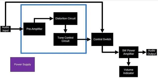
Audio In - 1/4" jack input, here we plugged in an instrument audio signal
Preamplifier - Audio filter and signal amplification that amplifies the input signal before it reaches the power amplifier stage.
Distortion Circuit - A circuit based on a simple diode clamp, since we have a gain option in the preamplifier stage, we can adjust the gain of the clipped signal.
Tone Control Circuit - Simple bandpass filter that changes the characteristics of the output frequency.
Control Switch - Used to select the audio input path that will go to the power amplifier circuit. One of: The input signal through the instrument or the signal processed by the preamplifier.
5W Power Amplifier - Audio Power Amplifier Circuit, designed in bridge load mode. We have two 2.5W LM380 ICs that can be doubled in bridge form.
Volume Indicator - Comparator based circuit designed with a basic peak detector, 4 comparators and 4 outputs, connected to front panel LEDs.
Audio output - 1/4" jack differential output, please note that there is no ground grid on the output. Here we connect 4-8 ohm speakers, but not more than 5W.
Step 2: Parts and Instruments
Complete List of Everything You Need: Parts
A. Common parts:
1.5mm diameter wire
Plastic case - I used a 100x150mm plastic case. Make sure it is easy to drill.
0.3mm wire - for electrical connection.
1 x prototyping board - preferably single sided, easy to desolder if there is a soldering error.
16 x Shrink Tubing - Protect unshielded wires.
3 slider potentiometer knobs.
4 x metal screws - box enclosure
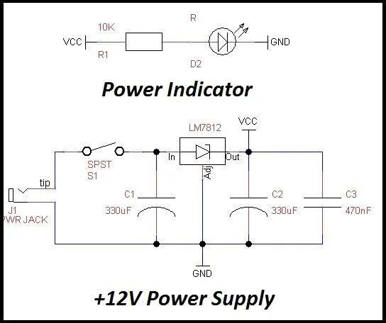
14-18V DC power supply, 0.9A or higher.
B. Front panel assembly:
1 x SPDT switch
2 x SPST switches.
2 x 1/4" phone jack - guitar in\speaker out.
3 green LEDs.
2 red LEDs.
1 x Power jack - 15V power input.
8 x Label Stickers - Add instructions on your device.
C. Electrical parts:
1. Resistance:
2 x 1M
12 x 10K
5 x 1K
1 x 220K
1 x 100K
2 x 470K
1 x 10R-power resistor
1 x 2K2
2. Capacitor: 2.1 Non-polarized:
1 x 1n
1 x 10n
1 x 50n
1 x 50p
1 x 22n
1 x 470n
1 x 100p
1 x 100n
2.2 Polarized:
2 x 10u
3 x 330u
3. IC and other parts:
1 x LM7812-12V linear regulator.
2 x LM380-Audio 2.5W Power Amplifier.
2 x LM324 - low power quad operational amplifier.
1 x LM741 - general purpose operational amplifier.
1 x 1N4007 - general purpose diode.
2 x 1N5817 - signal diodes
3 x 100K slider potentiometers - can be rotated - no difference.
Step 3: Schematic - How the Device Works
The schematic is very simple:
The switch "throw" pin is connected to the potentiometer, its opposite pin is connected to ground, and the wiper pin is connected to the LM380 IC input. Note that the 100K potentiometer will be used as a volume control. The LM380 IC is connected in bridge-tied load mode.
Both ICs amplify sound signals with small amplitudes, but the second LM380 acts as an inverting amplifier - so at the output of both ICs we get an amplified signal that is larger, but with opposite polarity. By connecting a load to these outputs, the differential voltage across the load is doubled and therefore the maximum power at the load is doubled. prove:
P(differential)=2*V*I=2*P(single)=2*2.5=5W
The differential output (J3 symbol on the schematic) is the audio output of the amplifier. I used a 1/4" phono jack, so I just connected the output speakers directly to the amp.
Step 4: Soldering
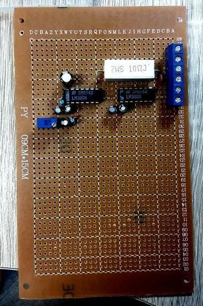
Soldering is the most fun part of building, especially audio circuits.
First, it is critical to carefully consider the soldering process and determine where the components will be placed. It was much easier for me to break the whole circuit up into groups and solder them part by part:
Power Amp > Preamp > Volume Control > Power Supply > Terminal Blocks > Cut Circuit Board.
Let's describe the steps:
1. LM380 Power Amplifier Circuit: This is the last but not least in the schematic, but the...
Read more »
 sidsingh
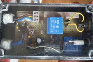
 Entunassa
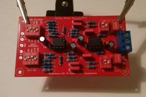
 carbono.silício