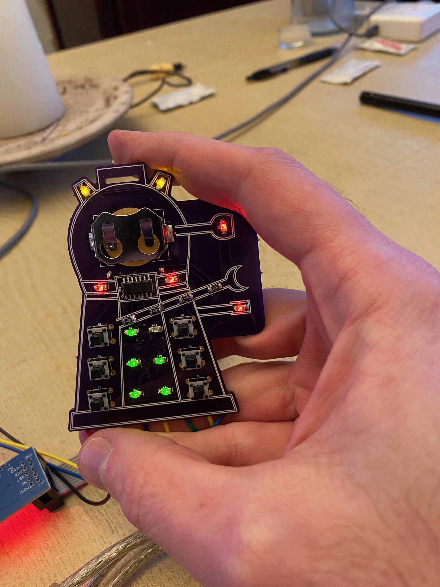
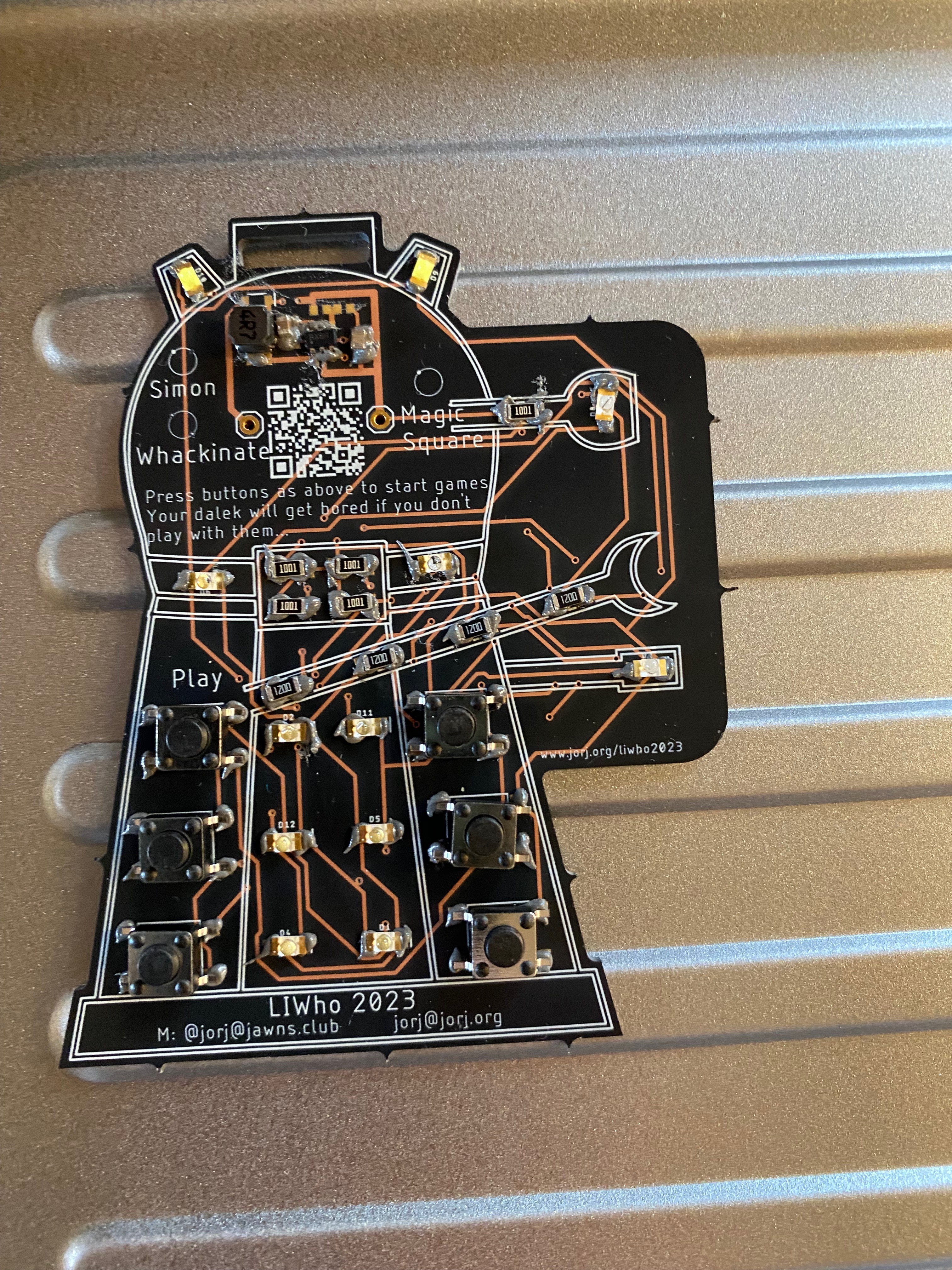
• Part 5: The Con(vention)

    Jorj Bauer08/19/2023 at 20:53 0 comments

    Well, the Daleks are live, and this project is now public!


    100 badges went to attendees in a few hours on the first day. The first night, the leaderboard started to explode with people figuring out how the game works.

    Many lessons have been, and continue to be, learned - including that people have no idea how to rip paper off of a receipt printer. But fun is being had, and that was the point of this project...

  • Entry 4: Part Selection, redux

    Jorj Bauer08/11/2023 at 18:31 0 comments

    Self, Ideating: Hey! If I took those whodads I've got lying around and pair them with the whatsits in this box, I'd have a jiggery thing. How cool! I can whip that up and it'll use up some of these parts I've been hoarding forever.

    Self, First Revision: Those parts are wrong, and those parts are wrong, and these parts are right but I'd had 25-year-old stock and they're obsolete. What the heck do modern parts even look like? I should get some samples. And of those I'll use these to test another version, I think they'll work.

    Self, Second Revision: I've got all these parts that came in the mail but don't remember why I picked the ones I put on the first revision. Which seem to work fine, but maybe one of the others is better for some reason. Should I make another prototype? Yeah, I'll make another prototype.

    Self, Third Revision: Ooh, I like this. But hey, there's this cheaper part? If I'm going to make a lot of them I should look at making it cheaper...

    Self, Fourth Revision: Huh. I've got more parts to store than I had to begin with. Again. I wonder how that keeps happening?

    Curse you, self. This is a vicious cycle. That I don't think I could live without.

    Anyway: that's exactly how this build went. I have a pile of tactile through-hole switches, a small number of SMT LEDs, and some leftover ATTiny 84a SMT chips. Those were the parts I used for the first prototype, which is why it's a hodgepodge of through-hole and SMT work.

    Come to think of it, I think I also had the battery cages around from another project. A lot of re-use all around.

    So here are some of the questions that came up while I was replacing all of the parts.

    "If I mis-match the LEDs to get different colors, how much leakage current will light up the wrong lights in the Charlieplex array?"

    A: not much. I stuck with LEDs from the same family, and while there are occasional small flickers of the wrong light barely lighting up, I decided the color was too cool a feature to skip.

    "How much force is the right amount of force for a tactile switch? What's the right stem length?"

    A: I thought that "the least amount of force they sell" would be the right answer, making the buttons as easy as possible to press. But it turns out that I didn't like them under about 120 grams of force; they felt too flimsy. And it turns out that filtering on stem length is a little tricky, because some manufacturers measure the stem length based on how proud it is of the surface of the switch; while others measure from the base of the switch. Either way - the switches I liked the most weren't the ones I wound up using, because ... stem color also played in to it. (A little more on that later.)

    "What's a good design for a boost power circuit?"

    A: No idea, but the reference design and layout for the MCP1640 worked well here.

    "How small a part is too small?"

    A: Well, 1206 parts are much more manageable than I feared. But 0402 parts are definitely too small. The first resistors I got for the voltage boost circuit were 0402 - and they did work, but there's no way I'd want to hand pick-and-place those at scale.

    "Are all CR2032 battery cages the same?"

    A: I'd assumed so... but no, not really. The cheap ones I got from Digikey in my last batch are very, very tight while the more expensive ones I'd originally gotten from Mouser are perfect.

    "How much of this circuitry can I strip out and still have it be good enough?"

    A: This was actually part of "how cheap can I make this?" which I only asked myself after making the first 100 PCBs. Yeah, that might sound a little odd, but hang with me for a moment here.

    I do kinda have an annual hobby budget, and my Dalek building or badge design or large format printing all come from that. The original design for these badges started in 2020 and ended in 2023, and had loose competition for my time with an Aiie! display update (which I haven't published on that project page yet, apparently). So it was fairly easy for me to say that it didn't matter too much what 100 of these badges wound...

    Read more »

  • Entry 3: Developing the Dock

    Jorj Bauer08/10/2023 at 17:07 0 comments

    So let's talk about the programming interface. The UPDI programming spec is fairly easy, and I wound up coding an ESP32-S3 so that it could reprogram a badge using UPDI. That meant that the dock could suddenly give firmware updates, which is a great bonus - I'd have a way to reprogram badges at the con, should some bug surface. I already had plans for a public dock, for reasons I'll get in to later - this all aligned well.

    But it still triggered debug mode occasionally. Rarely. But once it did, the badge was stuck in debugging mode. Since it's self-powered by its battery, once it's in debug mode it's gonna stay there until something tells it not to be.

    But there's a great feature of the UPDI interface on these Series-0 Atmel devices where you can require a +12v pulse on the UPDI pin to activate it. Some code needed updating in my dock protocol, and I needed a way to generate +12v out of the +5v I was using, but one Dickson Charge Pump later I've got something usable with the parts lying around my house.

    The 0.1uF capacitors in the lower-right are fed two out-of-phase square waves from the microprocessor, which build up potential across the diodes; the voltage winds up boosting over the span to somewhere around 13-14v, and the final 1N4742A diode clamps it to 12v. Here you can see it discharging a few +12v pulses and charging back up...

    The (lower) yellow trace shows the pulses, while the (upper) cyan is showing a steady state of +12v that discharges and then takes a little bit to charge back up again. (Note that the voltage scales are different.)

    Great! That's #1 sorted.

    The power consumption issues took a little while to crack. First, I'd accidentally misread the vendor's specs on the power boost IC, and used resistors one-thousandth the values they were supposed to be. They leaked a commensurate amount of current, and I wound up doing some surgery on Dalek Agatha to figure it out. (This is about when she got her name -- she was a bit of a mystery!)

    I cut the power trace from the boost circuit to the ATTiny and measured its current draw - no problem, low as can be. It took a few minutes of puzzling at the schematic to see it...

    The 562k and 976k resistors are a voltage divider to give the 1640 a reference. I'd put in 562 ohm and 976 ohm resistors, which gave it the correct ratio.

    The only logical parts of "why is this drawing so much power" were the resistors; I measured current through them and found that, yes, they were responsible; and started yelling about how the manufacturer's reference schematic was awful before I realized I'd misread it. Whoops, my bad. Runtime jumps from under 2 days to about 4 days, and I'm in the ballpark.

    The rest of the win was in software. The general goal was to wake on both a hardware interrupt (if someone presses any button, wake up) and a timer interrupt (wake up periodically to see if we should nag the user to play a game). The combination is pretty easy to set up, but it turned out to be a little tricky to get it in to a lower power state during its power-down time. We'd run through dozens of batteries in the house looking at runtime, running stopwatches to be sure, and when I finally got it right, we jumped from 4 days ... to literal months of runtime.

    Now, the final badges will get more use in 3 days than we gave them in those months - but I'm pretty confident that it will last the 3 conference days pretty easily.

    Why didn't I just trust the current draw math, you say? These batteries are about 200mAh; it should be easy math to take how many milliamps are being drawn and divide appropriately to see how many hours it would run. There are two problems with that...

    First: CR2032 batteries are pretty terrible at high draw. If there are spikes where the battery draws high current, it's going to deplete the battery faster than math would normally dictate. I didn't know how badly that would affect these badges with occasional flashing blinky LEDs.

    And second: getting...

    Read more »

  • Entry 2: "Rapid" Prototyping

    Jorj Bauer08/10/2023 at 13:55 0 comments

    In 2022, the return of LIWho was announced and I unpacked the goodies I'd stored in 2020. Now, what was the problem again? Right - I ran out of program space. It could play a simple pattern-matching Simon; Whack-a-mole, where it keeps lighting up lights for you to hit buttons; and Magic Square, a game from the 1980s Merlin where you tried to light up all of the lights. I had some concept of Tamagotchi in it, where it nagged you to play Simon occasionally; and a bit of social interaction where you could "introduce" badges to each other with special button-press sequences. But I couldn't really tie it together without more program space; these were just disjointed bits of code that were kinda fun on their own - and probably would have been fine - but weren't enough for me.

    So I spent a few months building and rebuilding bagdes with different processors. The two likely culprits were the ESP8266 (oooh, wifi!) and the ATTiny 1606 (a beefier and more modern '84a).

    The problems I needed to solve:

    1. Noise immunity. The serial port docking protocol, and programming pins exposed on pads, meant occasional hangs or reboots. I played with an ad-hoc I2C bus for docking and reprogramming via bootloader, but it really didn't help at all.
    2. Code space. I had ideas for other code to write, but couldn't shoe-horn it in place.
    3. Power. Up til now, I'd been running everything directly off of a CR2032 battery. The lights dim as you play; I kept looking for LEDs that ran at lower voltages to get the brightest possible experience. It felt like a race to the bottom.
    4. Improvement of the Tamagotchi and social aspects. These existed, but didn't really feel like part of the experience.
    5. More knowledge about SMT LEDs. I picked some basically at random for the charlieplex display, and needed to understand more about available parts.
    6. More (some!) experience with reflow soldering. I'd been soldering these together by hand, and knew that wouldn't scale up to the hundred badges I wanted to produce.

    LIWho 2022 came and went (and we did not attend), so I set my sights on solving all of those things for the 2023 con.

    January, 2022: an ESP8266 prototype. Space for two batteries (or a AAA battery pack) on the back, and the ESP-12F mounted on the back as well. The first prototype where I tried out SMT switches.

    At the top is a boost supply, built around the MCP1640. I knew the ESP-12F would need a more stable supply to work well, and as a bonus it got me bright LEDs through the battery's full life. (I also replaced the mono-colored LEDs with different colors by area - white at the top, blue on the right, yellow on the collar, and green down the skirt. Because why not?)

    First ESP-12F prototype

    This certainly had a ton of programming space, and the possibility of direct Wi-Fi communication with centralized APIs. I thought a little about switching to an ESP32 to use BLE for badge-to-badge communication, but wanted to tame the battery life issues first: this thing was a monster, and needed at least AAAs to run for any significant period. Even with WiFi disabled, I never got close to the runtime I needed: at least 3 days, 4 for safety. (My best efforts got to about 20 hours if I remember correctly.) The biggest problem was that, without an external interrupt, I couldn't wake from deep sleep. I did design an external interrupt prototype which sort of worked, and might have gotten to the power consumption I wanted, but the parts cost really started to skyrocket.

    Now, I've not mentioned the half a dozen changes while playing with the three boards I got in that order - reducing current usage by swapping resistors; trying different kinds of LEDs; playing with different serial port configurations. With the 12F it still wasn't really fixing any of the problems except for storage space. I just had new vast areas of potential problems. Combined with the increasing cost, I decided to put the whole thing down for a month.

    When I picked it back up, I hacked in an ATTiny-1606. The first...

    Read more »

  • Entry 1: How It Started

    Jorj Bauer08/10/2023 at 13:49 0 comments

    I started small. Really, I did.


    My 40% scale Special Weapons Dalek is, as its name says, smaller than it could be. It was my "Gateway Dalek" in to the world of prop building ("It'll make you feel good") and lead to a full-sized (Well, 94%, so it clears doorways) Imperial Dalek named Geo. So I've got a pile of Dalek guts, parts, molds, cabinets for transportation, spraypaints, screws, washers, fiberglass chemicals, etc., which eventually meant I needed to buy an actual trailer to house and transport all of it.

    I might have a problem.

    Way too much spraypaint

    So when the bug caught me in late 2019 to do something new, I had to think hard about where I'd build it and how I'd store it. The only sane conclusions (not that sanity is really a prerequisite here) were (a) don't, because there's no space left; (b) buy a new house, because this one is full; or (c) find a way to not store it when I'm done.

    Obviously (a) isn't going to happen. It's not in my genes. I tried playing video games, watching TV, and generally doing nothing for a year after knee surgery and found that, not surprisingly, I don't like it. And (b) is right out; we love our not-too-huge somewhat-overcrowded house, and as we'll be empty nesters in the near future it should kinda come back to being the right size for us in our continuing middle aged years. Besides, I'd wind up on the hook for spending more time cleaning a bigger house - obviously time I could be using better by just cluttering up whatever space we've got.


    So how does one make something for a convention and then not have anything physical to show for it after the fact? It would have to be something to give away. With some kind of continued use. And this is where I started thinking about electronic conference badges.

    In early 2020, I designed a quick prototype and sent it off to oshpark.com. It mostly resembles the final product:

    First prototype badge

    Designed with a card edge connector in mind (lots of recent work on my Apple //e had me thinking about them), but not having bought an actual card edge socket yet, you can see I've got wires soldered to the pads on the back. 12 LEDs in a charlieplex arrangement, 6 through-hole buttons, 4 current-limiting resistors, an ATTiny84a to run them (I had some of them sitting around the house already) and I was hooked. This had to happen.

    There were, of course, some issues.

    The pads on the back were a source of noise, if your hands held the pads in "just the right way". (The dock protocol was just serial and it would occasionally engage while you were playing a game.) I went through a couple different prototype layouts - moving the serial to the front of the board, for example - and was never really happy with it.

    But the biggie was that I ran out of program space on the '84a. I switched from the Arduino IDE to a gcc toolchain, and I quickly ate that up too. When I started thinking about re-coding the whole thing in assembly, I put the project down and focused on pandemic life instead. There weren't any conventions coming up any time soon, and I had built a proof of concept that really resonated with me. Now it was just a matter of time.