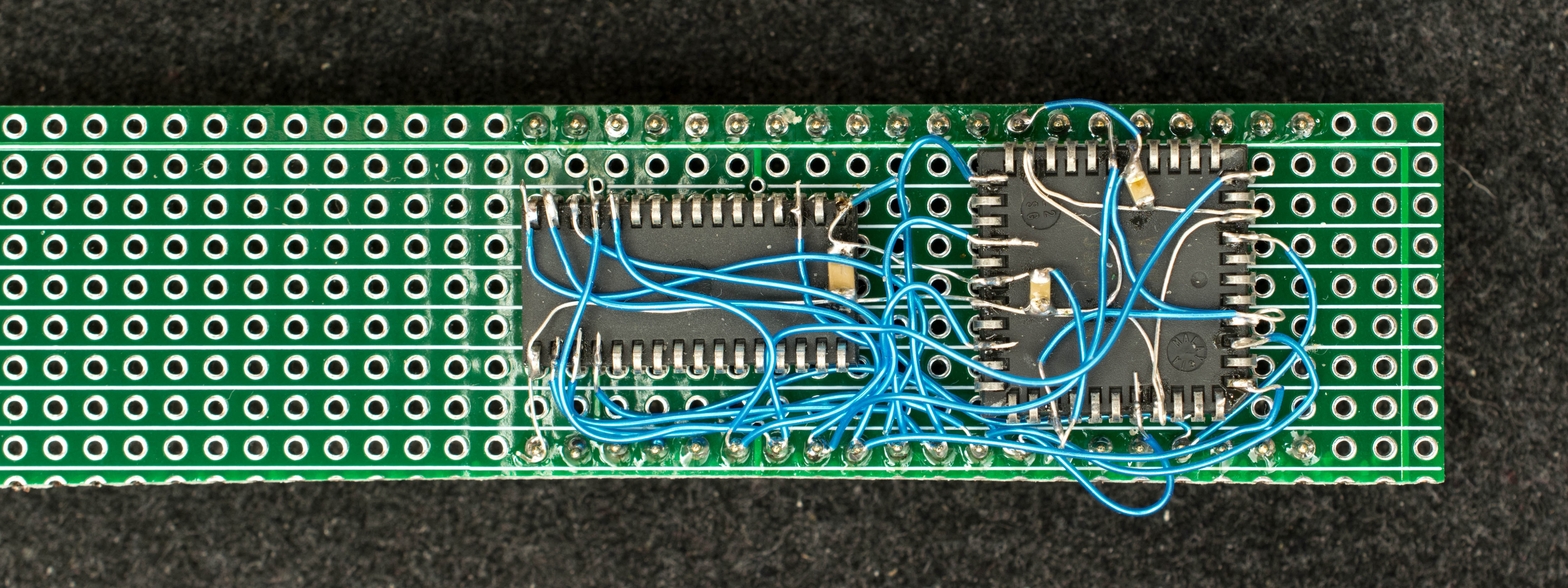
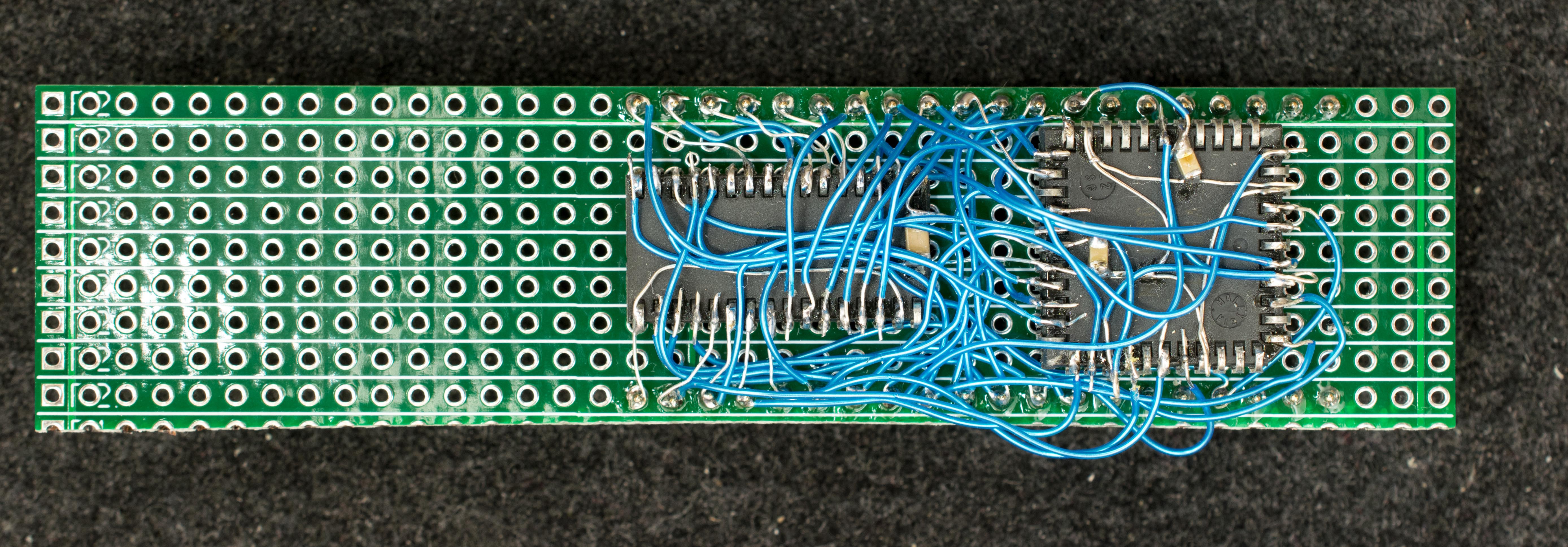
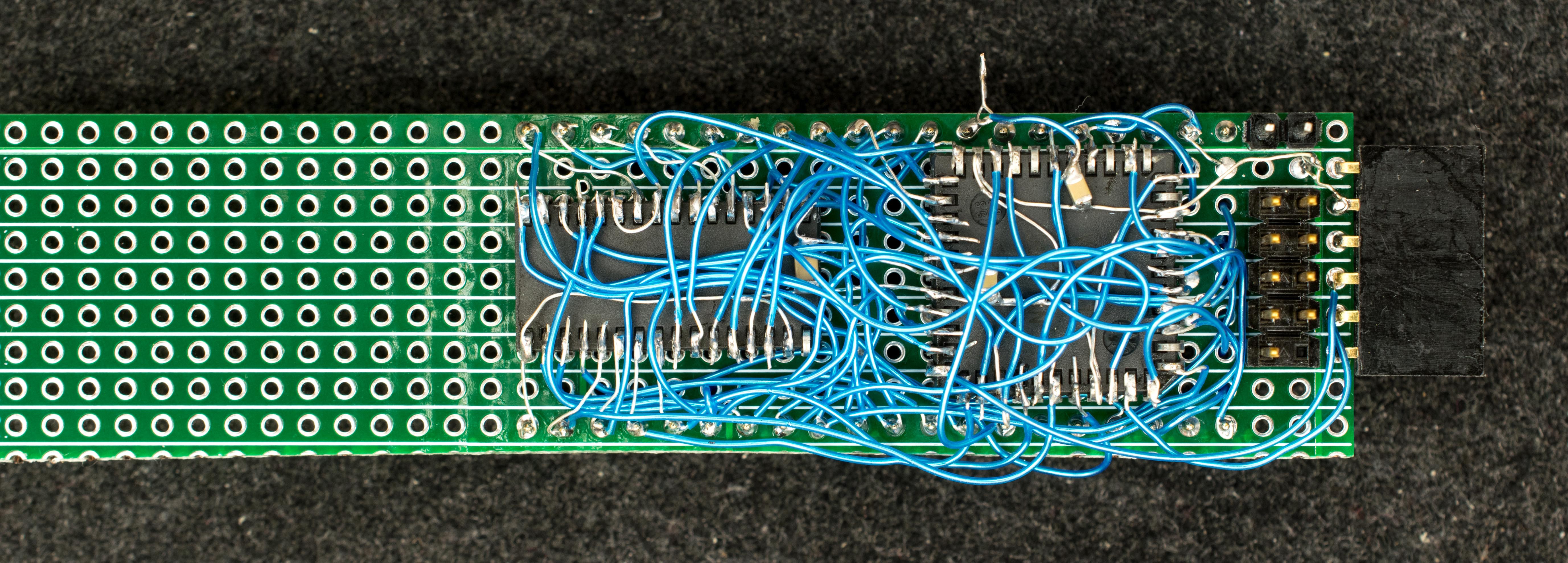
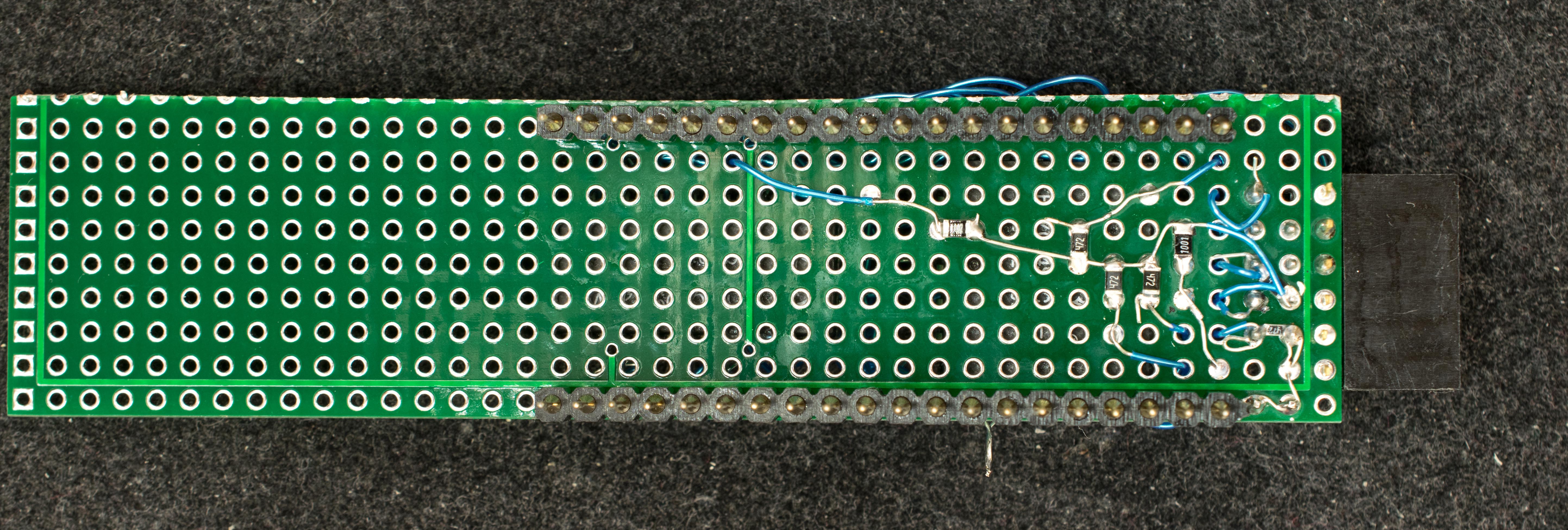
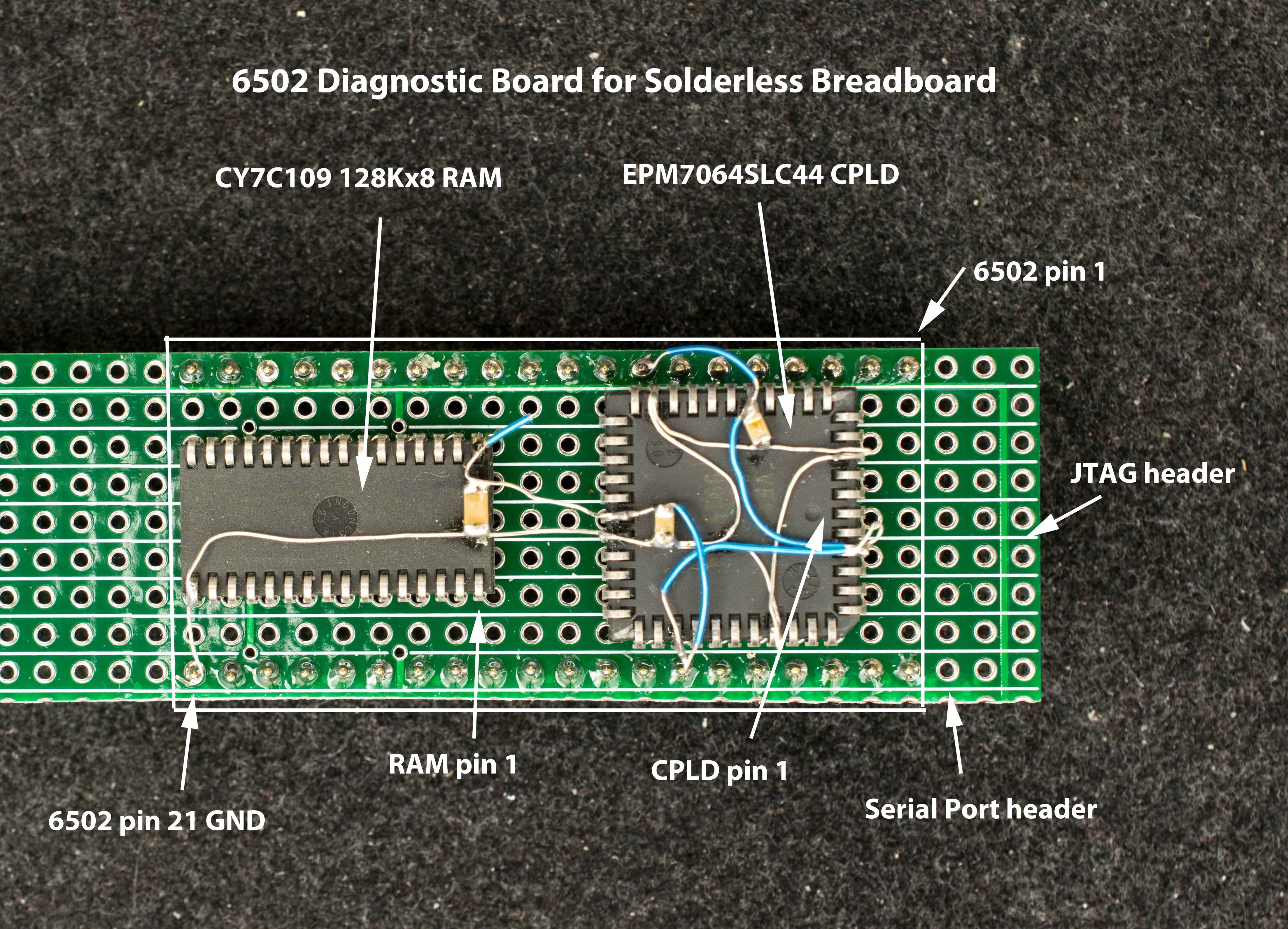
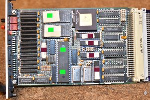
• Prototype construction

    Plasmode08/14/2023 at 19:16 0 comments

    The prototype was constructed using point-to-point soldering with 30-ga wire wrap wire.  It was all done under the inspection microscope.  There are not many connections, but they are rather tedious so I can only do a dozen or so wires per session.  It took me 2 days and several hours total to finish the prototype board.

    Picture below shows the data bus wired.

    Picture below shows address and data buses wired

    Picture below shows all connections wired, top view.

    Picture below shows bottom view of the completed prototype

  • Introduction and Proof-of-concept prototype

    Plasmode08/14/2023 at 02:15 0 comments

    Builder of 6502-based breadboard computer faces many challenges.  The first challenge is determining whether the 6502 and associated components are functioning; then making sure wires are hooked up correctly; then develop and test software for the prototype hardware.  Lots of efforts and time need to go into the unproven prototype before seeing any sign of life.


    The diagnostic overlay board is a small board, roughly the size of the 40-pin 6502. It has 40-pin that match the functionalities of 6502, but the spacing of the two rows are 0.8" so it can plug over the 0.6" 6502 DIP in the solderless breadboard.   The 6502 needs minimal wiring: power, ground, reset, and clock.  The clock needs to be standard baud-rate frequencies such as 14.7456MHz, 7.3728MHz, 4.9152MHz, 2.4576MHz, or 1,2288MHz.  This is because the diagnostic overlay board communicate with a desktop over serial terminal which expects standard serial port speed.


    The diagnostic overlay board is derived from the CRC65 design but without the compact flash interface and using external 6502.  It has a 128K RAM and a 64-macrocell CPLD (EPM7064S).  The CPLD has a small (64 bytes) bootstrap ROM, a serial port, and address decoding logic.  Diagnostic overlay + 6502 can bootstrap over the serial port and load/run application downloaded over the serial port.  CPLD can be re-programmed to provide other modes of operation such as instruction tracing and simple bootstrap/testing.


    Different flavors of diagnostic overlay board can work with other DIP retro processors such as Z80, 6809, 8085, 68008, but this project will start with 6502.  Since this is a new concept, I'll start with a manually wired prototype.  Attached is the schematic and layout of the two components on perf board.