-
1Specification
item content remarks Power-supply voltage 5V Assuming USB power supply controller voltage 5V, 3.3V consumption current 180mA (scan time 1.2mS) Typical value for a single sensor board, power consumption 1W Typical value for a single sensor board, Scan time board alone 1.2mS or more, 1 channel 150uS or more Scan time parallel continuation 800uS or more, 1 channel 100uS or more* Cost price $67 - In order not to reduce the detection distance, it is desirable to use 150uS or more per channel.
- The measured distance of the sensor varies slightly depending on the microcontroller. Since the distance accuracy is poor, the distance cannot be determined by specifications. However, most microcontrollers can detect a distance of 8 inches.
-
2Hardware of the sensor
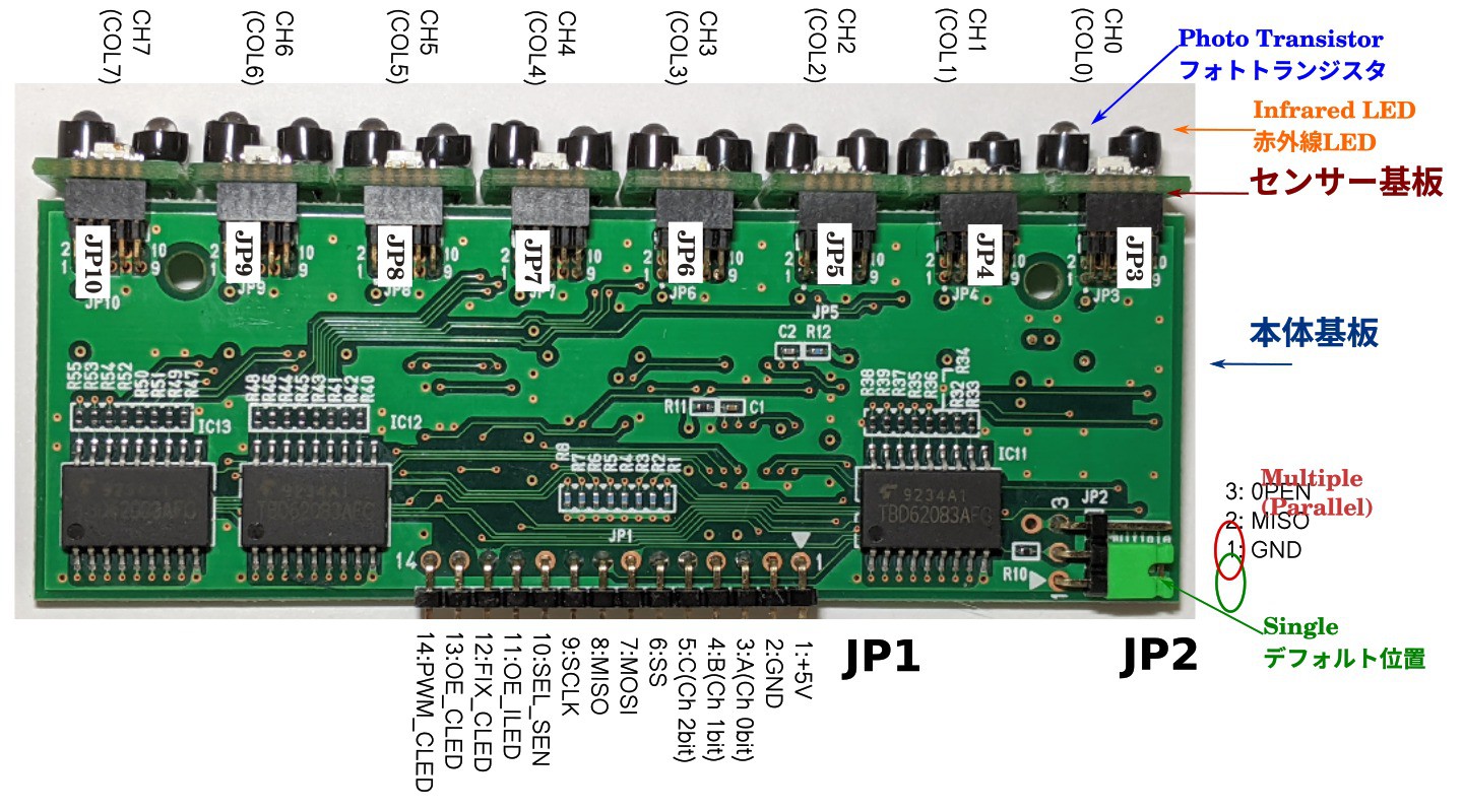
Main board
![]()
Main board pinout (JP1)
pin number PIN name explanation 1 +5V Vcc 5V 2 GND GND 3 A Sensor channel 0bit 4 B Sensor channel 1bit 5 C Sensor channel 2bit 6 SS SPI Slave-Select (active-Low) Substrate selection when connecting in parallel. 7 MOSI SPI Input 8 MISO SPI Output (3.3V/5V switching JP2) 9 SCLK SPI Clock. Sometimes also "SCK" is used. 10 SEL_SEN Determine if SPI is for sensor or CLED
High: Sensor (AD converter), Low: CLED11 OE_ILED ILED Output Enable *ILED: Infrared LED
ILED enable/disable * The AD converter is read both when the ILED is on and when it is off.12 FIX_CLED CLED Shift Register Latch *CLED: color LED
Reflect the value of the shift register to the output13 OE_CLED CLED Output Enable
CLED output ON/OFF14 PWM_CLED Adjust the brightness of the CLED with PWM (Pulse Wide Modulation) control Short to 13pin or 5V when not using PWM summary
- SEL_SEN pin for SPI switching of sensor (AD converter) and CLED.
- Set the ILED channel with ABC.
- After CLED transfers data to the shift register, it is reflected in the output with a FIX_CLED pulse.
- CLED ON can adjust the brightness with AND output of 13pin and 14pin and PWM of 14pin.
Sensor sensitivity adjustment method
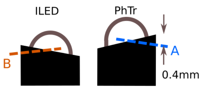
ILED and PhTr You can adjust the sensitivity of the sensor by moving the black cover up and down, but please be careful as it may deviate from the optimum sensitivity.
*ILED: Infrared LED, PhTr: Phototransistor, CLED: color LED
![]()
If the black cover is too high and cannot be lowered, cut the black cover as shown below. Priority is in the order of A and B in the figure below.
![]()
Precautions when sensing through transparent plates such as acrylic and transparent OLED
- Close to the sensor or less than 0.4 inch away from the sensor. Otherwise, the sensitivity will drop significantly.
- Before turning on the power, set the board so that it does not move. The sensor stores the surrounding brightness as a calibration value when the power is turned on. If the board is moved after the power is turned on, the calibration values will no longer match and accurate sensing will not be possible.
- If you use acrylic, the sensitivity will be about 5% lower than without. With transparent OLED, the sensitivity is significantly reduced by about 1/7.
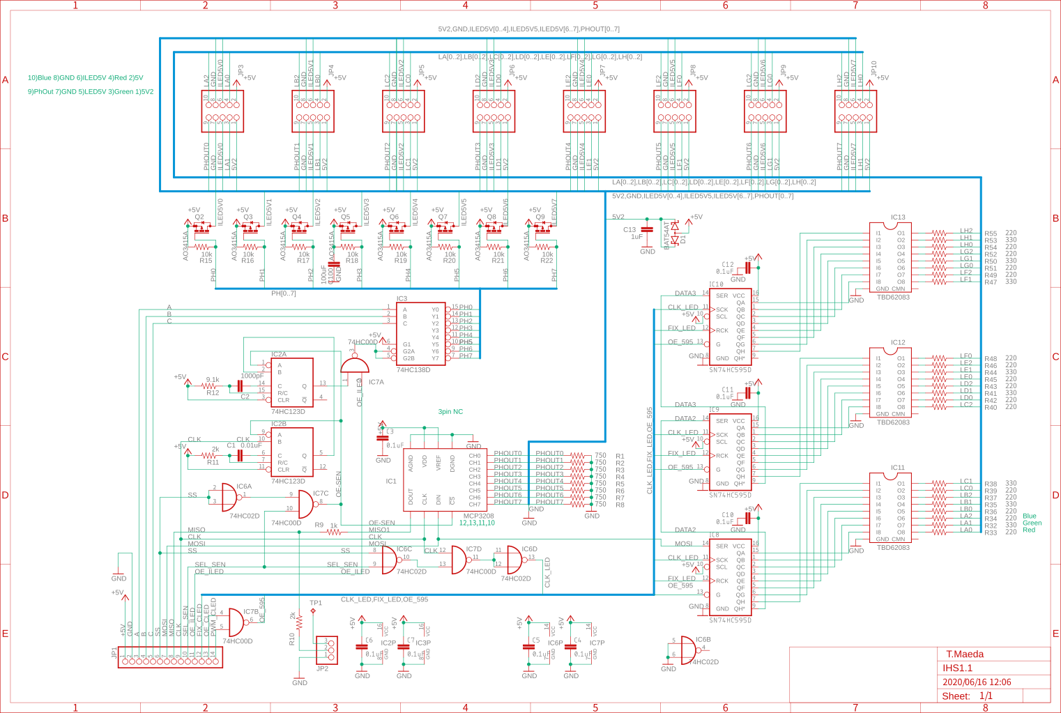
Main board circuit diagram
![]()
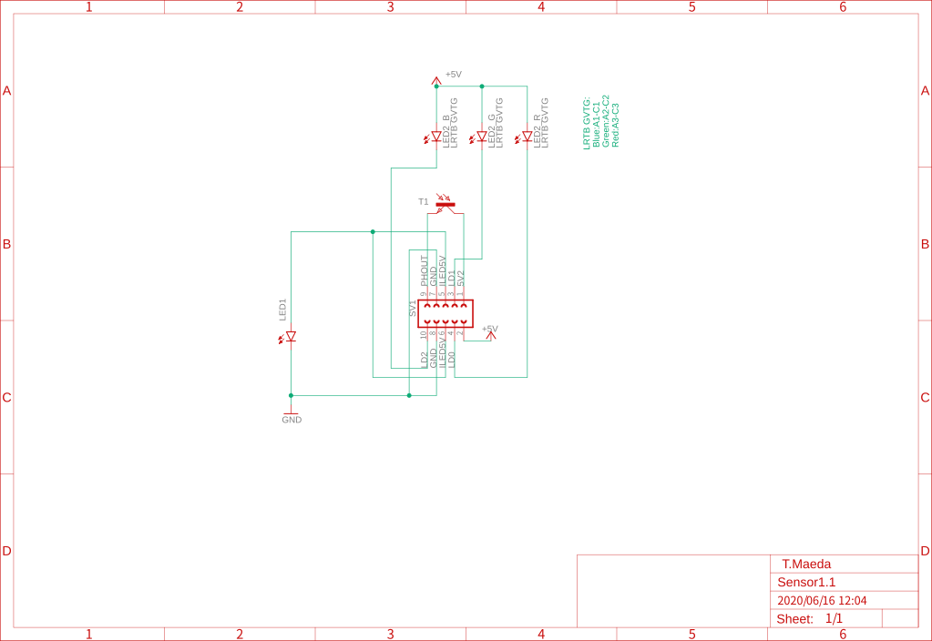
Sensor board circuit diagram
![]()
SPI and ILED drive timing
![]()
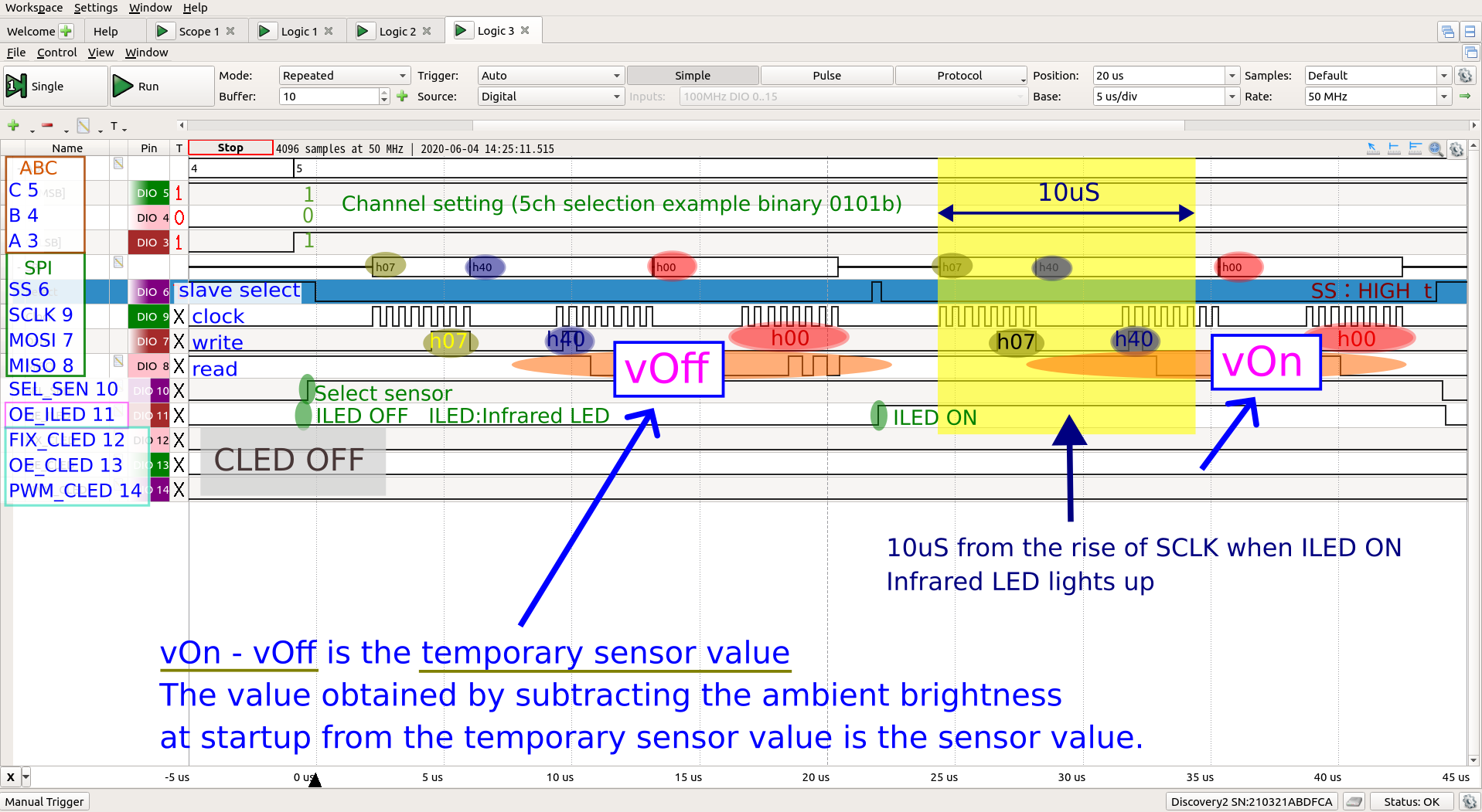
The infrared LED drive is triggered by SPI SS. Please note that this timing will vary slightly depending on the microcontroller and software library. The library has been confirmed to work on Raspberry Pi 3 and 4, Arduino Uno and Nano Every, and mbed Nucleo.
SPI and ADC read timing
![]()
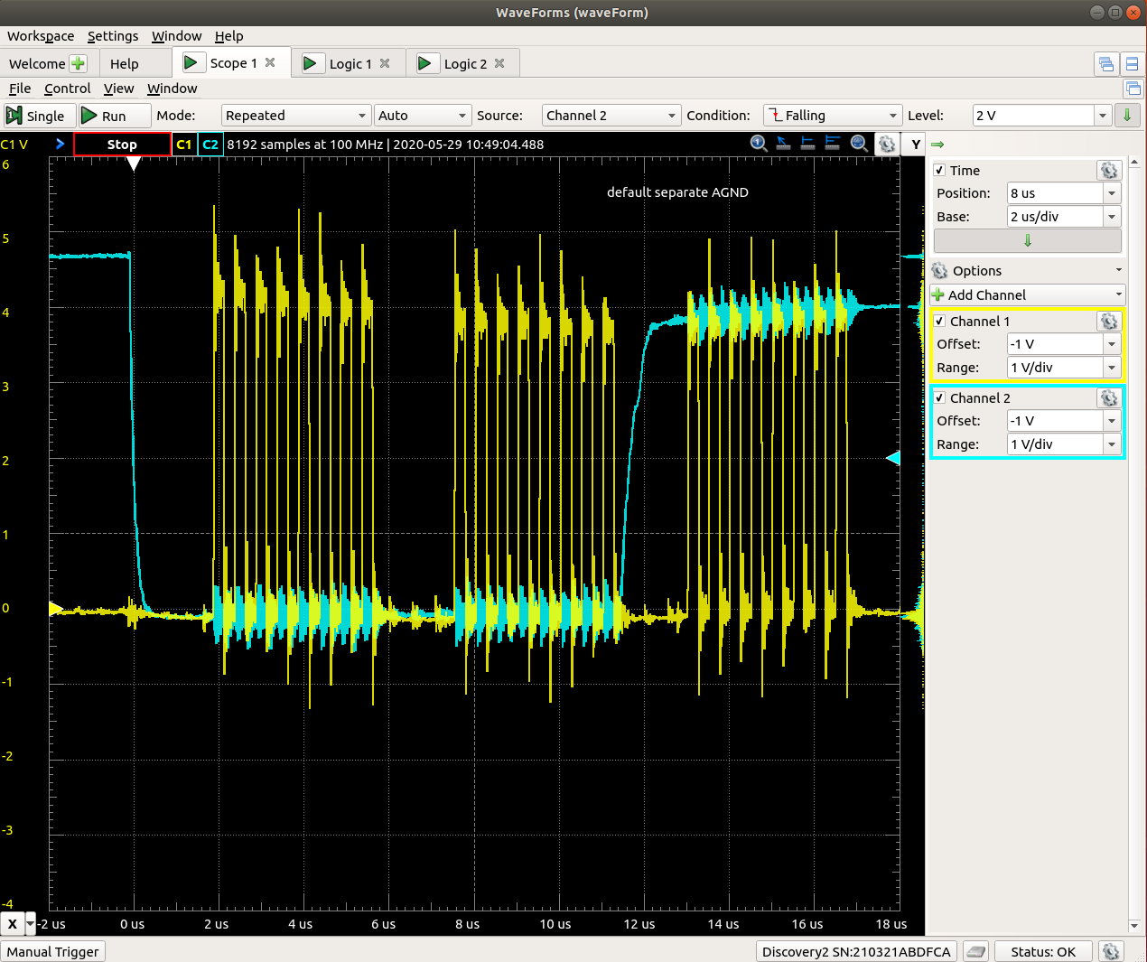
The reading timing of the AD converter is near the center of the diagram. The on time of an infrared LED is 10 microseconds, but even when it is turned off, the output voltage of the phototransistor does not drop immediately. The sensor readings are therefore relatively stable.
Note
The sensor's infrared LED is fragile, so please do not touch it unless it is in danger of falling out or if it is unavoidable.
Please turn off the power before inserting or removing the sensor. If you insert or remove it during operation, it may be damaged.
If the sensor is operated directly under the air conditioner, the air conditioner remote control may not work due to the effects of infrared rays. In that case, you can avoid it by changing the location or angle.
-
3Software and interface of the sensor
SPI interface setting (AD converter/shift register)
- SPI-MODE:0
- CLOCK:2MHz
- One cycle (time interval between accesses to the same ILED) is 1.2mS or more
AD converter reading procedure
1. OE_CLED:LOW
2. A,B,C :Sensor channel setting
3. SEL_SEN: HIGH Select sensor, do not select CLED
4. OE_ILED:LOW ILED OFF * ILED: Infrared LED
5. SS :LOW
6. SPI-read AD read value:vOff
7. SS :HIGH
8. OE_ILED:HIGH ILED ON
9. SS :LOW
10. SPI-read AD read value:from
11. SS :HIGH
12. Temporary sensor value:fromOn - fromOff Save in an array
* The value obtained by subtracting the ambient brightness measured at startup from the temporary sensor value is the sensor value.Logic analyzer sensor reading diagram
![]()
- Select the channel with A,B,C
- Select the sensor by setting SEL_SEN to High
- Turn on OE_ILED and emit infrared rays only during the second reading
- Make the AD converter channel the same as A, B, and C channels.
Read code of AD converter (Arduino C++)
8 sensor readings
void Sensor::setAd(bool bInit) {// bInit:add val to adAryInit[]
    for (int col = 0; col < COL_LEN; col++) {// COL_LEN:8
        setCol(col, bInit);    // *** sensing ***
    }
    if (!bInit)                // *** set CLED ***
        cled.set(val);        // sensor-data, indicator
}
Reading of a single sensor
void Sensor::setCol(int col, bool bInit) { int ledSta = digitalRead(OE_CLED); digitalWrite(OE_CLED, LOW); out3bit(abc, col); digitalWrite(SEL_SEN, HIGH); digitalWrite(OE_ILED, LOW); // ILED-OFF int vOff =getAdc(col); // *** read ADC *** digitalWrite(OE_ILED, HIGH); // ILED-ON int ofOn =getAdc(col); // *** read ADC *** digitalWrite(SEL_SEN, LOW); digitalWrite(OE_ILED, LOW); // ILED-OFF digitalWrite(OE_CLED, ledSta); if (bInit) adAryInit[col] += vOn - vOff - (vOff >> 2) + (vOn >> 4); else adAry[col] = noMinus(vOn - vOff - (vOff >> 2) + (vOn >> 4)- adAryInit[col]); val[col] = ad2val(adAry[col]); // adAryInit[col]: Ambient brightness measured at startup } unsigned int Sensor::getAdc(int col) { digitalWrite(SS, LOW); SPI.transfer(6 | (col >> 2)); unsigned char r1 = SPI.transfer(col << 6); unsigned char r2 = SPI.transfer(0); digitalWrite(SS, HIGH); return ((r1 & 0x0f) << 8) + r2; } -
4CLED Data transfer method
How to write a (8x3=)24-bit number to the shift register to drive the color LED.
1. Set SEL_SEN LOW : Select CLED.
2. Set OE_CLED and PWM_CLED LOW : Turn off the CLED output.
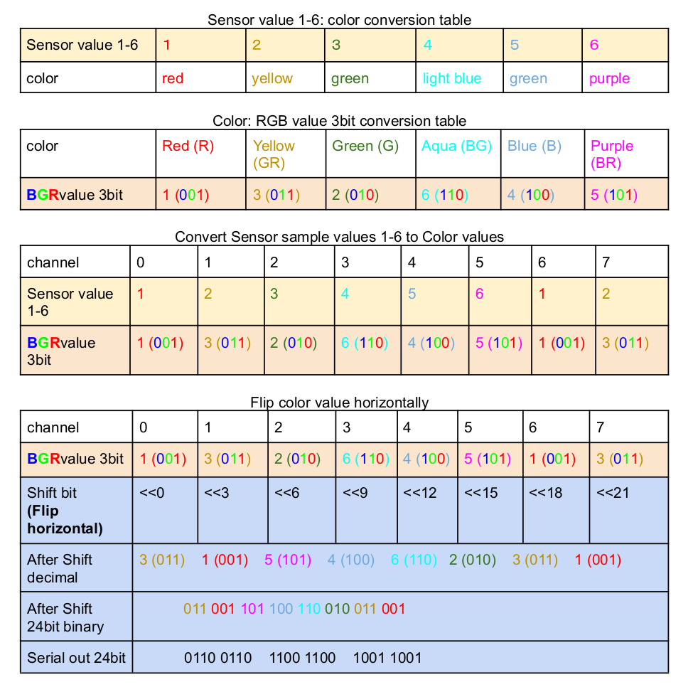
3. Convert the colors of sensor values 1-6 to 3-bit RGB values (table below) and transfer them to shift register with SPI
4. When FIX_CLED is HIGH and LOW and one pulse is output, the value is reflected in the shift register.
5. Set OE_CLED and PWM_CLED HIGH : CLED glows.
![]()
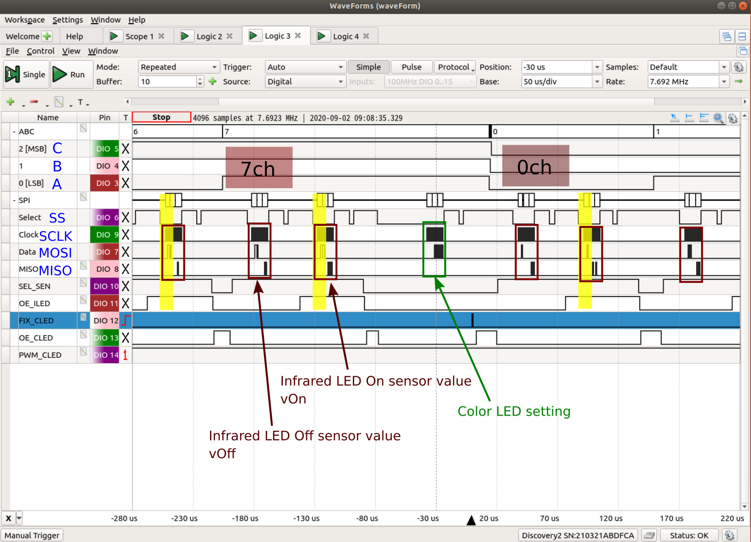
Logic analyzer CLED write
![]()
CLED is controlled by shift register 74HC595. When writing, set SEL_SEN to Low, select CLED, and write the value to the shift register using SPI. After that, when FIX_CLED is turned on and off, the written value is stored in the shift register memory. To light up CLED, turn on OE_CLED and PWM_CLED at the same time. If you do not use PWM, it is convenient to leave PWM_CLED on.
CLED code
void CLED::set(byte* pAry, bool isInd) { // 1-12[8]:{7, 3,..}
    if (isInd) { // *** blink indicator ***
        int indiCnt = INDI_CNT << ((inOn) ? 0 : 2);
        if (++inCnt == indiCnt) {
            inCnt = 0;
            inOn = !inOn;
        }
    }
// ****************************
    unsigned long val24 = 0;
    bool isCledOn = false;
    for (int col = 0; col < COL_LEN; col++) { // LED number is opposit direction
        isCledOn |= (pAry[col] > 0);
        bool indOn = isInd && inOn && (col == COL_LEN - 1) && (!isCledOn); // indicator
        byte val1_6 = IndianOn ? 6 : array[col];
        val24 += (unsigned long)color[val1_6] << col * 3;
     // val1_6: Sensor value: 1 red to 6 red purple
     // color[val1_6]:Sensor value → BGR conversion value
     // val24: Color value, left-right flip, 24-bit value
    }
    digitalWrite(SEL_SEN, LOW);
    digitalWrite(OE_CLED, LOW);
    digitalWrite(SS, LOW);
    for (int b = 2; b>=0; b--) {
        SPI.transfer((val24 >> b * COL_LEN) & 0xff); // 8-bit by SPI
    } // write to shift register
    digitalWrite(FIX_CLED, HIGH);
    digitalWrite(FIX_CLED, LOW); // save the written value
    digitalWrite(SS, HIGH);
    digitalWrite(OE_CLED, HIGH); // Color LED on (with PWM)
}
Non-contact touch panel
Clean machine operation with non-contact touch panel. This sensor is a science fiction prototyping designed by imagining the future.
 Takahiro


Discussions
Become a Hackaday.io Member
Create an account to leave a comment. Already have an account? Log In.