 Takahiro
Interactive Hand Sensor
"Interactive Hand Sensor" can be detected with a resolution of 0.4~0.8 inch (1~2 cm).Can be applied to non-contact switches, non-contact touch panels, motion detection, etc.
8 sensors from 0 to 7 channels can be sensed in the shortest 1.2 milliseconds

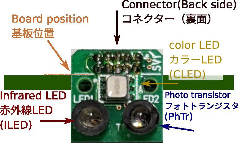
Photo reflector
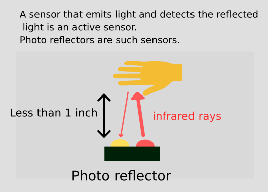
A photo reflector is a sensor that emits infrared light and detects the reflected light. They are used for line tracing in robots.
How it works
The principle of this sensor is an application of a photo reflector, which I call a "switching photo reflector".
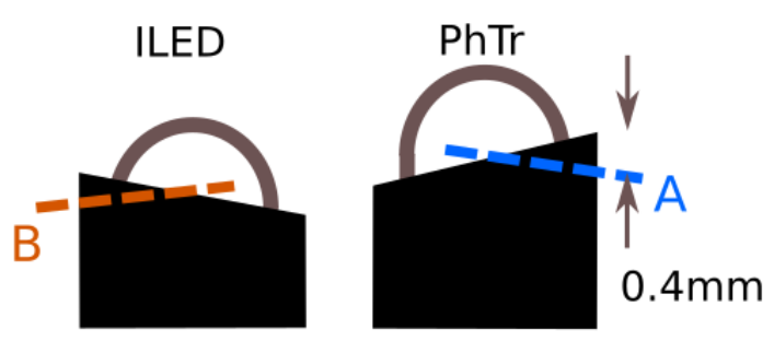
An infrared LED emits infrared light, and a phototransistor converts the light into an electric current, and the resistor converts it into voltage.
When reading the voltage with the AD converter, the infrared LED is lit at the SCLK timing of SPI Interface. It is driven for 10 microseconds without a current limiting resistor and emits strong light at a current of about 1.5A.
The sensor is not accurate in measuring distance. The intensity of the reflected light is not proportional to the distance. I'm throwing away accuracy of distance and taking speed.
The 12-bit AD converter number contains a lot of noise, so it's processed by a micro controller.
V = (A - B) - C
V: distance approximation
A: Reflected light from turning on the infrared LED
B: Reflected light with infrared LED turned off
C: Ambient brightness measured at startup
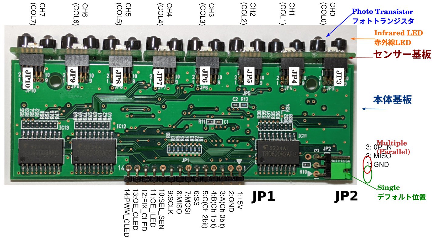
Block diagram
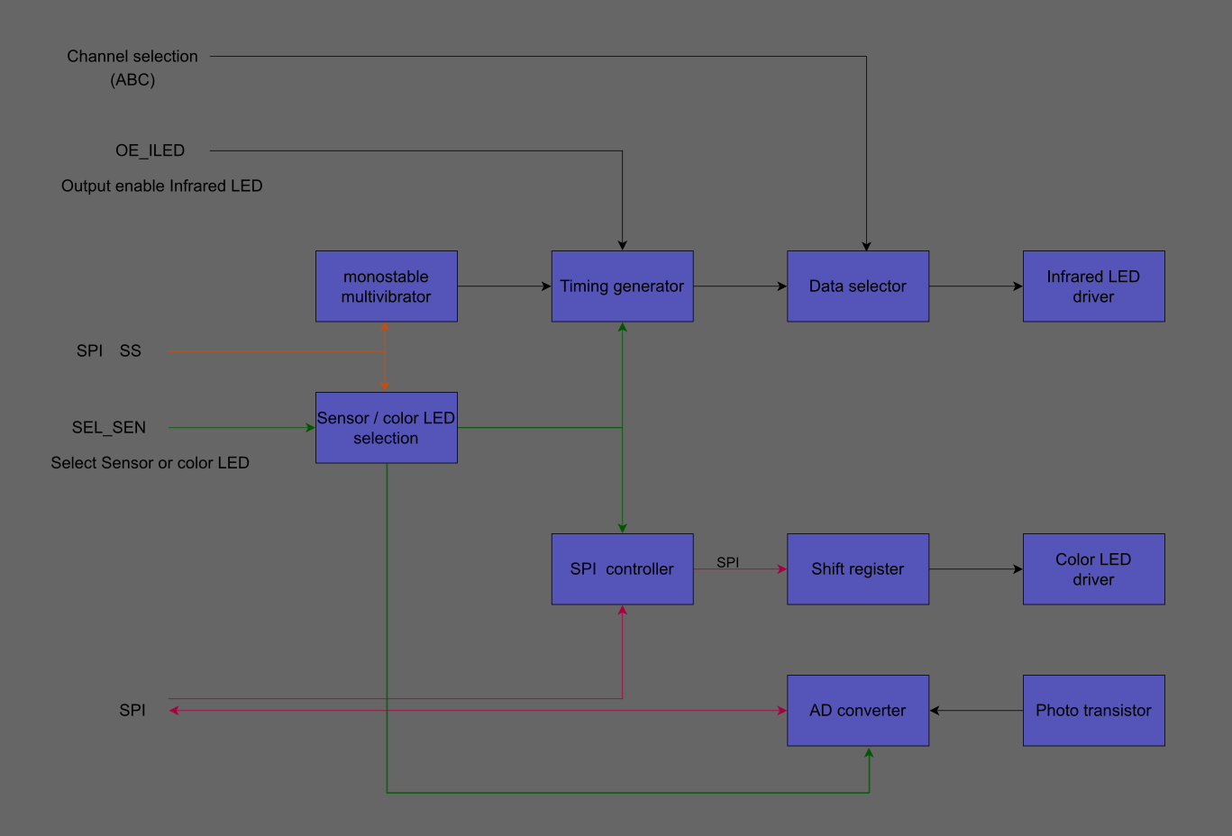
Sensor Operation
Before starting sensing, select the sensor with the SEL_SEN pin and set the channel. The first sensing session reads the ambient light intensity with an AD converter without emitting infrared light.
The second time, infrared light is emitted and detected in the same way, triggered by the SPI interface SS that is generated before reading the AD converter, which generates a 10 microsecond infrared LED drive signal, causing infrared light to be emitted. The AD converter reads the input value of the same number as the channel.
The infrared LED emission ends at the timing after the AD converter detects it. The difference between the second and first values is used to determine the approximate distance to the object.
Color LED Operation
Before starting the color LED operation, select the color LED with the SEL_SEN pin. Next, calculate the (8X3=)24-bit value for the color corresponding to the detected value. This value is written to the shift register via SPI, and when the output is turned on, the color LED glows.
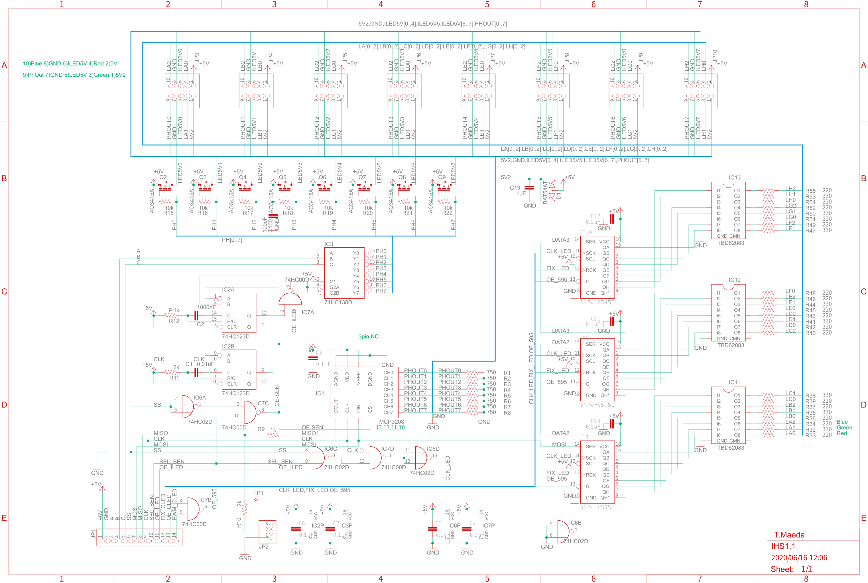
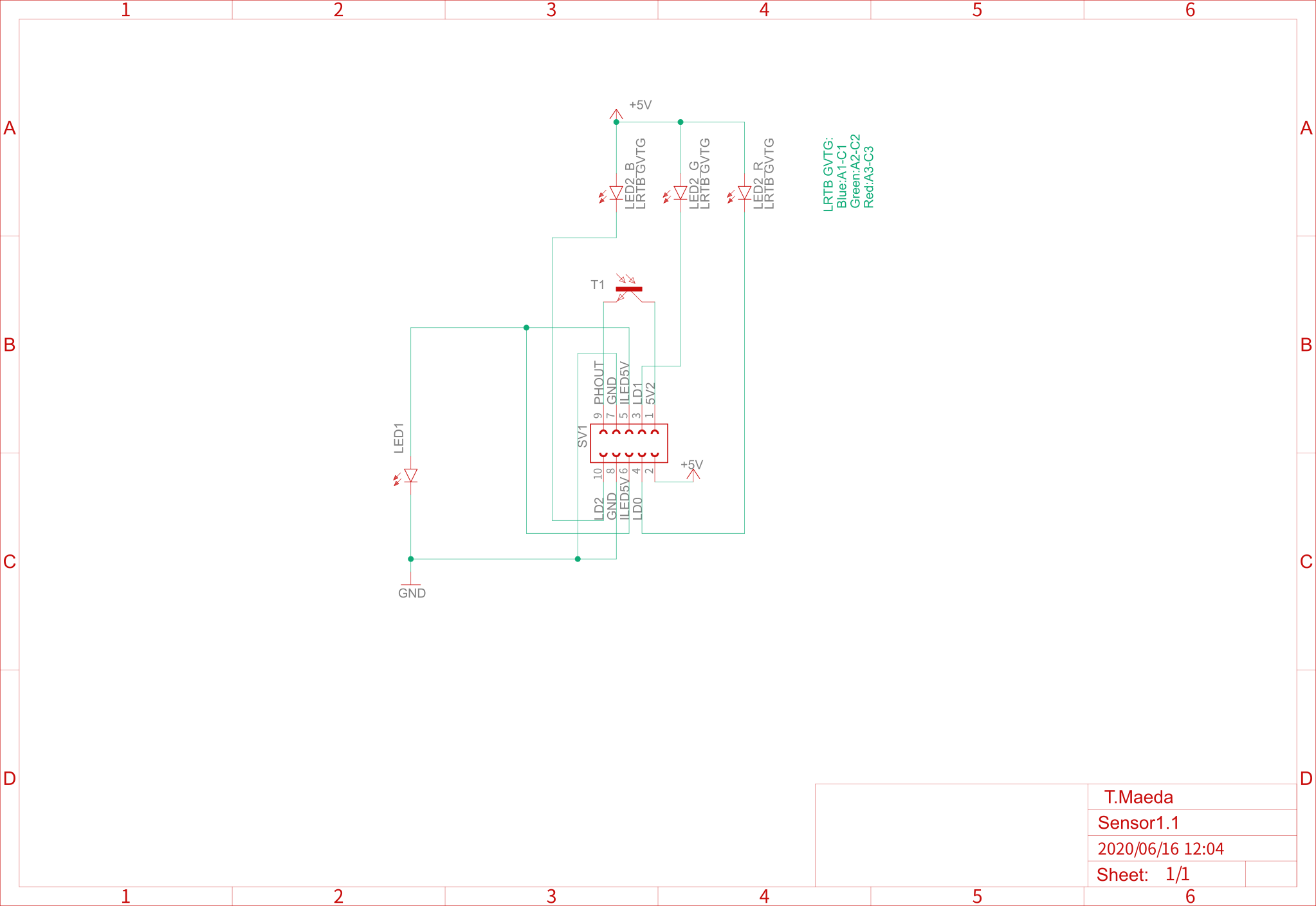
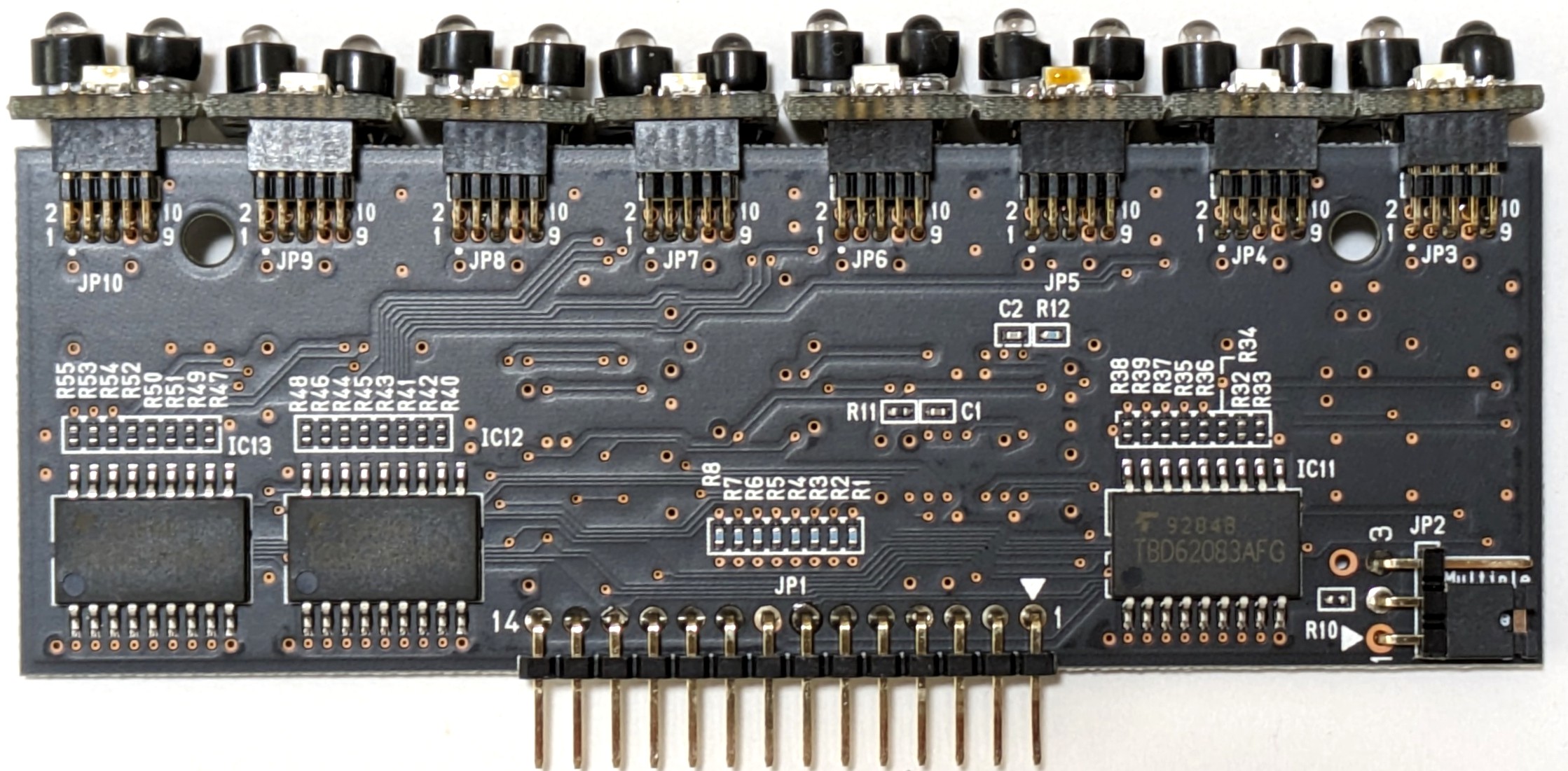
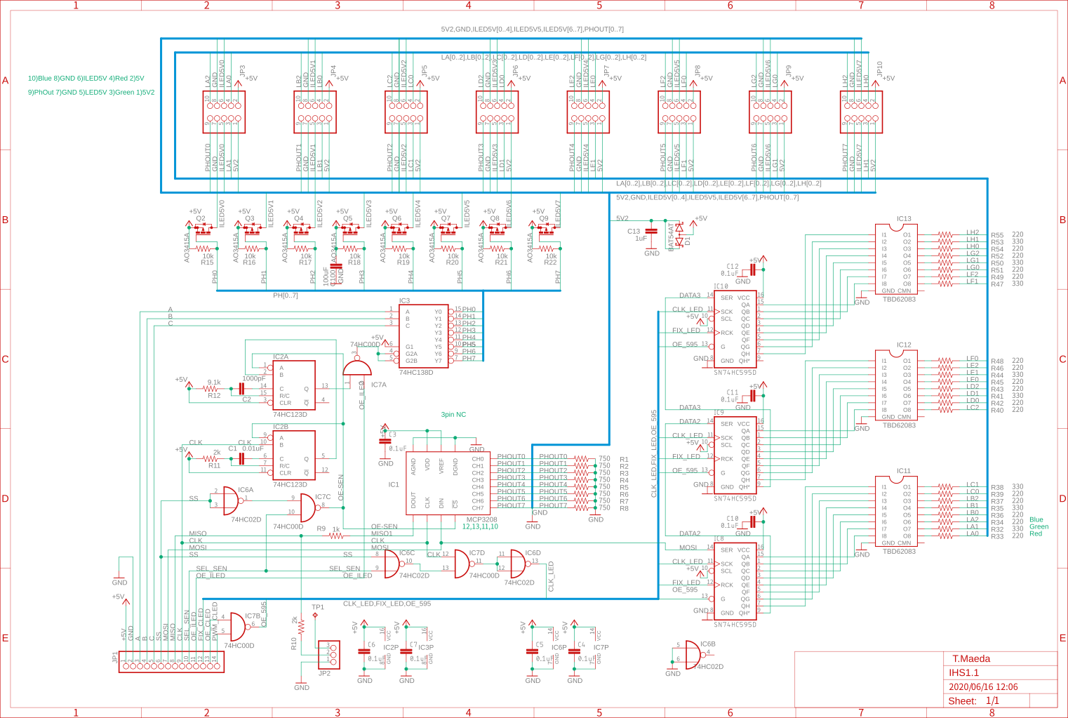
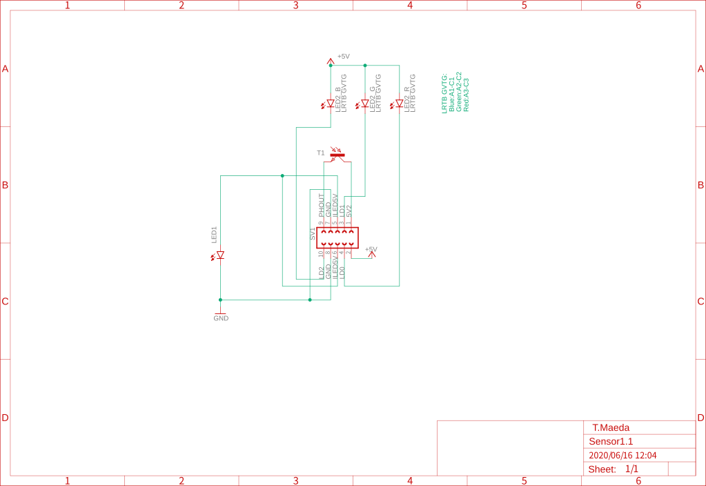
Circuit diagram
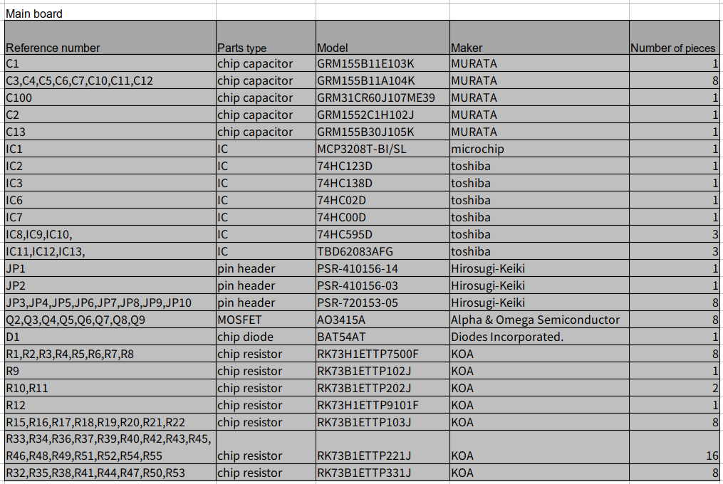
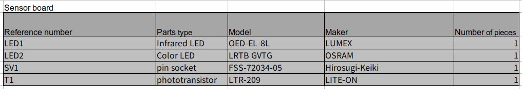
Parts list
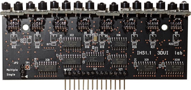
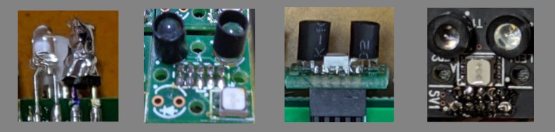
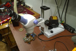
Photo
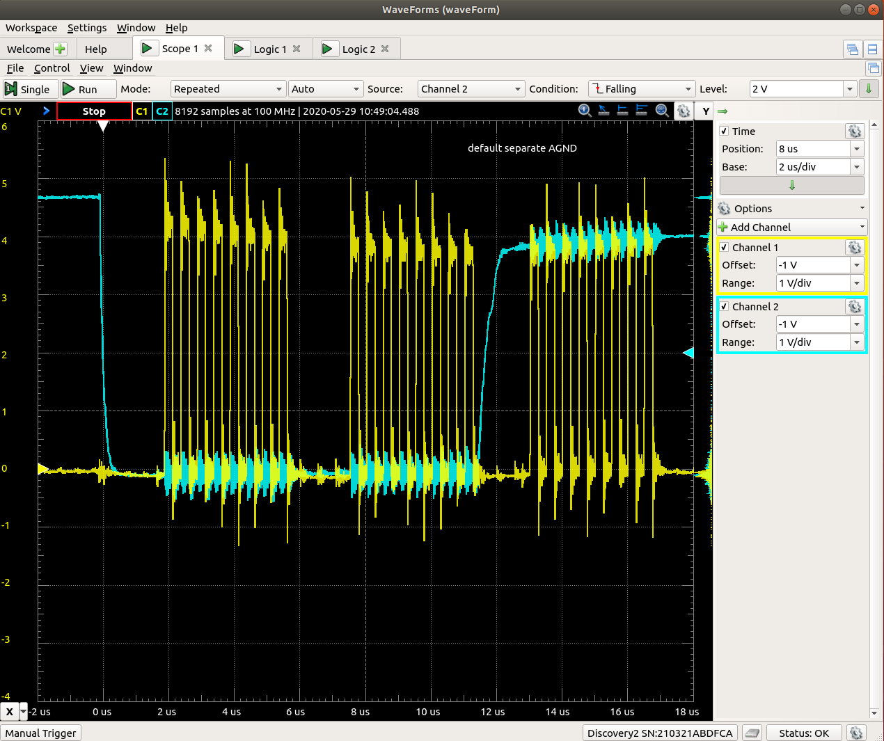
Logic analyzer
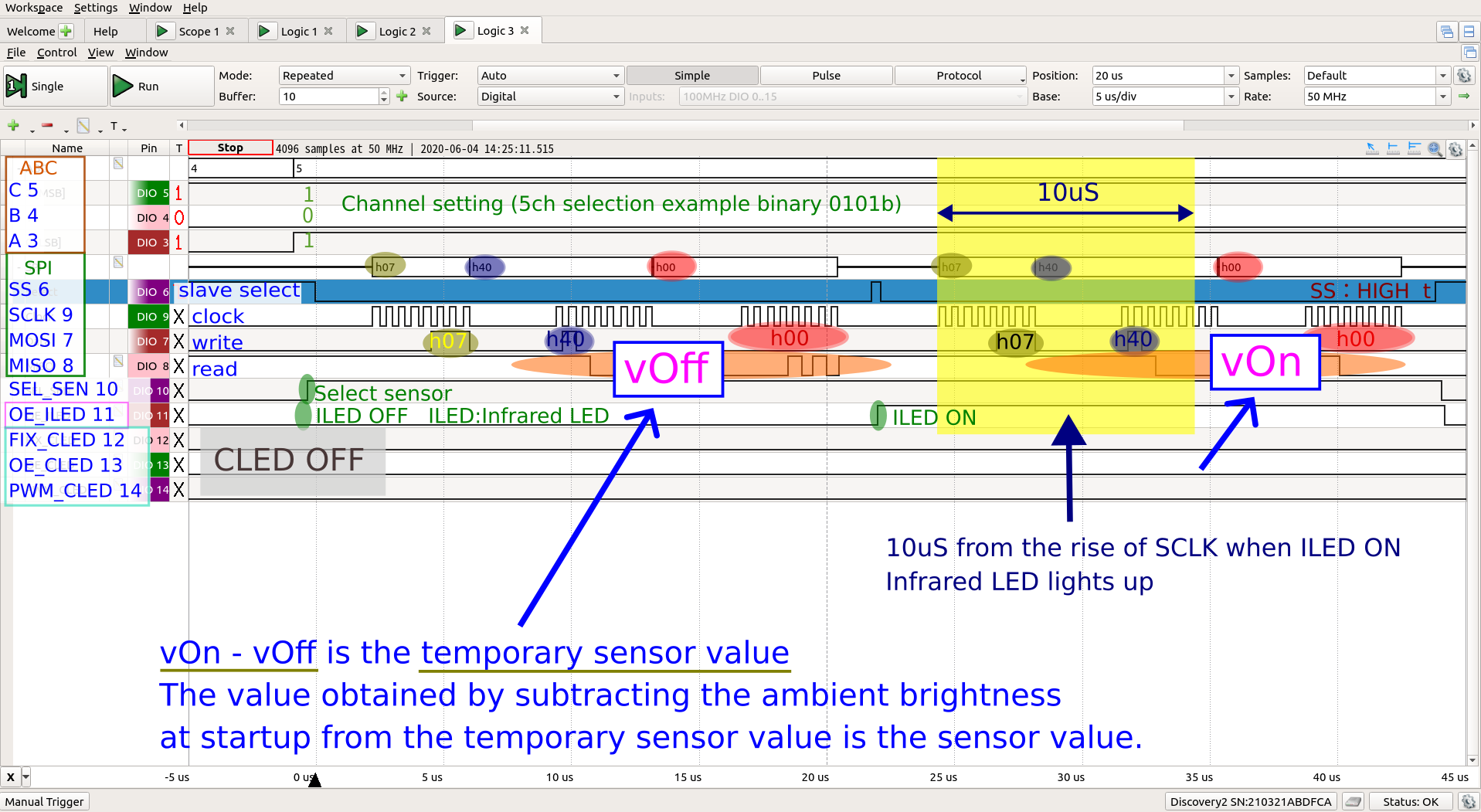
Logic Explanation
The AD converter reads the light intensity twice. Then, the infrared LEDs will emit light only for the second reading. Infrared LEDs draw currents that exceed their absolute ratings, so the on-time should be kept as short as possible. The MOSFETs that switch the LEDs switch ideally as in the simulation with zero delay. The distance value is the difference between his second value and the first value of the AD converter, minus the ambient brightness (calibration value).
Why sensors are now possible
I have worked in semiconductor failure analysis and am familiar with SEM and TEM photos of semiconductor failure areas. Most failures are caused by tiny distortions or cracks in the crystal. A device without crystal distortion or scratches can be said to be less likely to break.
Unlike LSI chips, infrared LEDs may not be subject to miniaturization of semiconductor processes, but as the precision of semiconductors is improving worldwide, I think they are becoming more difficult to break every year.
Recent semiconductors have a gray zone of about 100 microseconds. In the gray zone range, even if the current exceeds the absolute maximum rating, it will not be damaged. The sensor has been tested continuously for more than 2 years and 4 months without any deterioration.
This is on sale in Japan.
Non-contact touch panel
The sensor's infrared light passes through a transparent OLED...
Read more »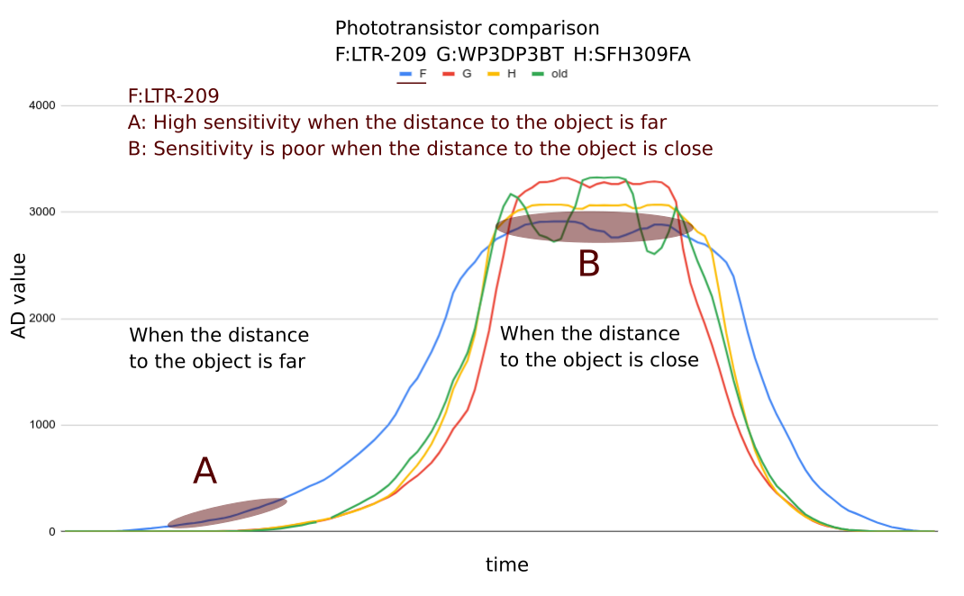


 DeepSOIC
 Michael O'Toole
 electronicsworkshops
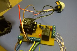
 Osman Mazinov