Introduction
This project is a sound-activated LED (light-emitting diode) in which the LED lights up whenever the sound sensor module detects a sound that exceeds the threshold that is set, such as a voice or clap. If a sound does not exceed the threshold of the sensor or in complete silence, the LED will remain unlit. The sound sensor module that is featured in this project has the capability of outputting a digital signal, although there are different variants that are capable of outputting both an analogue and digital signal. However, because this project makes use of digital signalling in switching the LED on/off, the digital output of the sensor will be used. This means that the sound sensor can only send two states depending on the input level (sound) that it receives: 1 (HIGH) or 0 (LOW). The sensor will send a 1 to the Arduino if it picks up any sound that exceeds its threshold value; otherwise, a 0 is sent for all sounds that do not exceed the threshold. In order to alter this threshold value, you can rotate the trimmer potentiometer that is mounted directly on the sensor module to modulate the sensitivity of the sensor. For the particular model in this project, rotating the potentiometer clockwise increases its sensitivity whereas rotating the potentiometer counter-counterclockwise decreases its sensitivity. It is important to note that depending on the model, the direction may be opposite for your sound sensor module. If the LED is not changing state (lighting up) when there is a loud sound nearby, you will need to alter the sensitivity of the sensor. Once again, any Python IDE installed on your Raspberry Pi should be compatible with this project but in this example, Thonny will be used. Alternatively, other IDEs such as mu IDE or even Nano that is built-in with the Raspberry Pi Terminal will work just fine. For this project, the components required are quite minimal and aside from the sound sensor module itself, you should be able to find all these components in your electronics workshop.
Wiring
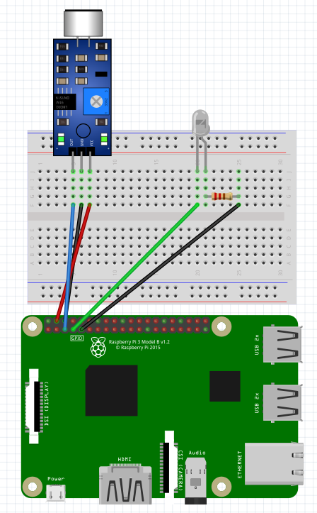
The wiring for this project is fairly simple as aside from the main sound sensor module and LED, not a lot of extra components are needed. In terms of the sound sensor module, the sound sensor module that is featured in this project has a 3-pin configuration where there is an output pin (OUT) that sends a digital output signal back to your Raspberry Pi. If your module has a 4-pin configuration, use the digital output (DO) pin but if your module has this same 3-pin configuration, the standard output/signal pin will work. In terms of the LED, the reason that a 220Ω resistor is connected in series with the cathode is to prevent the LED from burning out when applying a supply voltage of +5 volts. This serves as a current-limiting resistor so it can technically be connected in series with either the anode or cathode of the LED. If you are brand new to the Raspberry Pi, connecting wires to the Pi may be a bit daunting at first due to none of the 40 pins having any labels to indicate what pin it may be. This means that it is recommended that you always follow a pinout guide to identify pins and to additionally double-check your wiring before powering up the Pi to avoid any shorts. Other than that, the wiring for this project is fairly simple as aside from the main sensor, not a lot of extra components are needed. A circuit diagram of the wiring is also featured below.
- Sound Sensor Module: Connect the VCC pin to 5v (Pin 04) on your Raspberry Pi, the GND pin to GND (Pin 06) and the OUT pin to GPIO3 (Pin 05) on your Raspberry Pi.
- LED: Insert one 220Ω resistor in the breadboard in series with the cathode/negative (-) pin for the LED. Connect the end of that resistor to GND (Pin 09) on your Raspberry Pi. Connect the anode/positive (-) pin of the LED to GPIO4 (Pin 07) on your Raspberry Pi.
- Now, you are ready to get started with running the code and getting this project up and running!
Project Code
import RPi.GPIO as...
Read more »
 eGuidezhan
 Florian Wilhelm Dirnberger