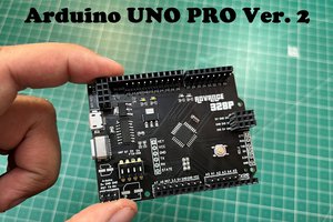
I made a series of Arduino Atmega328 boards and every new version has something new. We always learn something by doing practice of PCB designing. And This time I tried to exactly replicate the Nano board. Previous some version has minimal components yet they all are compatible but this time the board comes with extra protection features and USB type C. Most of the bigger companies design their top product without any component’s placement hints on PCB, means no silkscreen. And this time I do exactly the same. I have a datasheet and placing info which I can share separately but not directly on the PCB silkscreen which looks professional and quite similar to original.
Details
I made a series of Arduino Atmega328 boards and every new version has something new. We always learn something by doing practice of PCB designing. And This time I tried to exactly replicate the Nano board. Previous some version has minimal components yet they all are compatible but this time the board comes with extra protection features and USB type C. Most of the bigger companies design their top product without any component’s placement hints on PCB, means no silkscreen. And this time I do exactly the same. I have a datasheet and placing info which I can share separately but not directly on the PCB silkscreen which looks professional and quite similar to original.
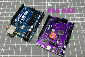
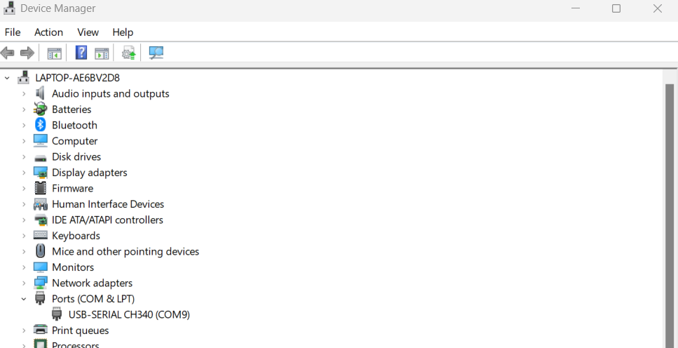
You can easily differentiate original Arduino boards from clones, the quality of silkscreen is better and they use little green-bluish solder mask. Comes with proper protection features. Arduino bootloader is pre-burned into the chip and programmer. And the boards are automatically interpreted by the Arduino IDE once the right COM port is selected. But our board is made by using compatible components that’s why it is easy to configure and rebuild.
Components required:
All the components used are very small, hand soldering is only possible if you are experienced. Try to gather all the components before ordering the PCB. We also provide Custom PCB design service just comment down below.
Atmega328p-SMD
CH340C
16Mhz ceramic resonator
0603 1K resistor x8
0603 10K resistor x1
0603 100nf capacitor x4
0603 1uf capacitor x2
0603 White LEDs
Reset Switch
USB type C connector
Pin headers
SS14 diode
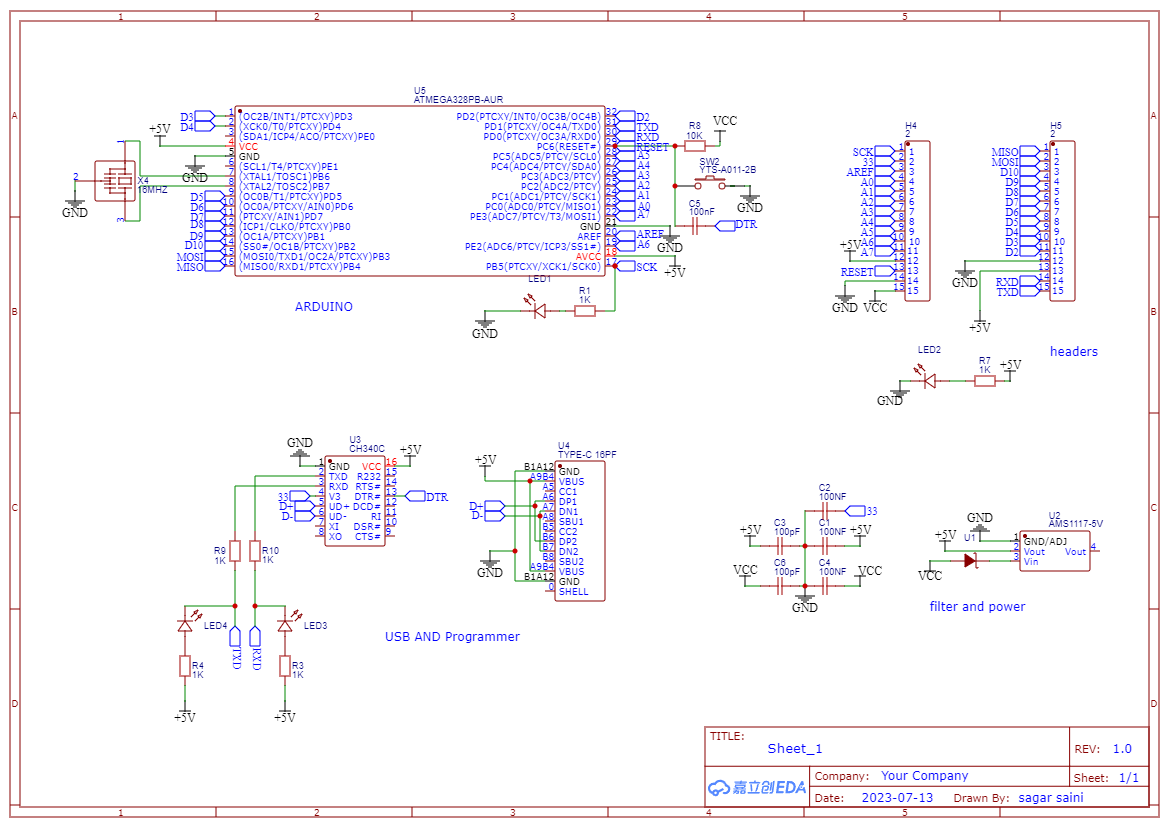
Circuit Diagram:
I divided the full circuit into 4 different sections you can see, First section is microcontroller section having all the activation circuit (Reset and Resonator). Second is Programmer section in which I used CH340C USB to TTL compatible IC and Serial programming circuit. In the third section we have power and filter section to reduce the overall voltage noise. In the forth section there are headers (2.54mm) for the Arduino’s GPIO.
Features:
USB type C
Fully compatible to Arduino IDE
Easy bootloader burning
Plug and play
User Customizable
PCB designs:
The PCB design is made in Altium designer and I exporter the design in the form of Gerber file. This file can be given to any PCB manufacturer for fabrication. But I always prefer PCBWAY – they provide great service and one stop solution to all of your needs. PCBWAY is the leading PCB manufacture, get your 10pcs of 2-layer PCB in just $5. Sign-up now and get free PCB Coupons for first order. Download Gerber file.
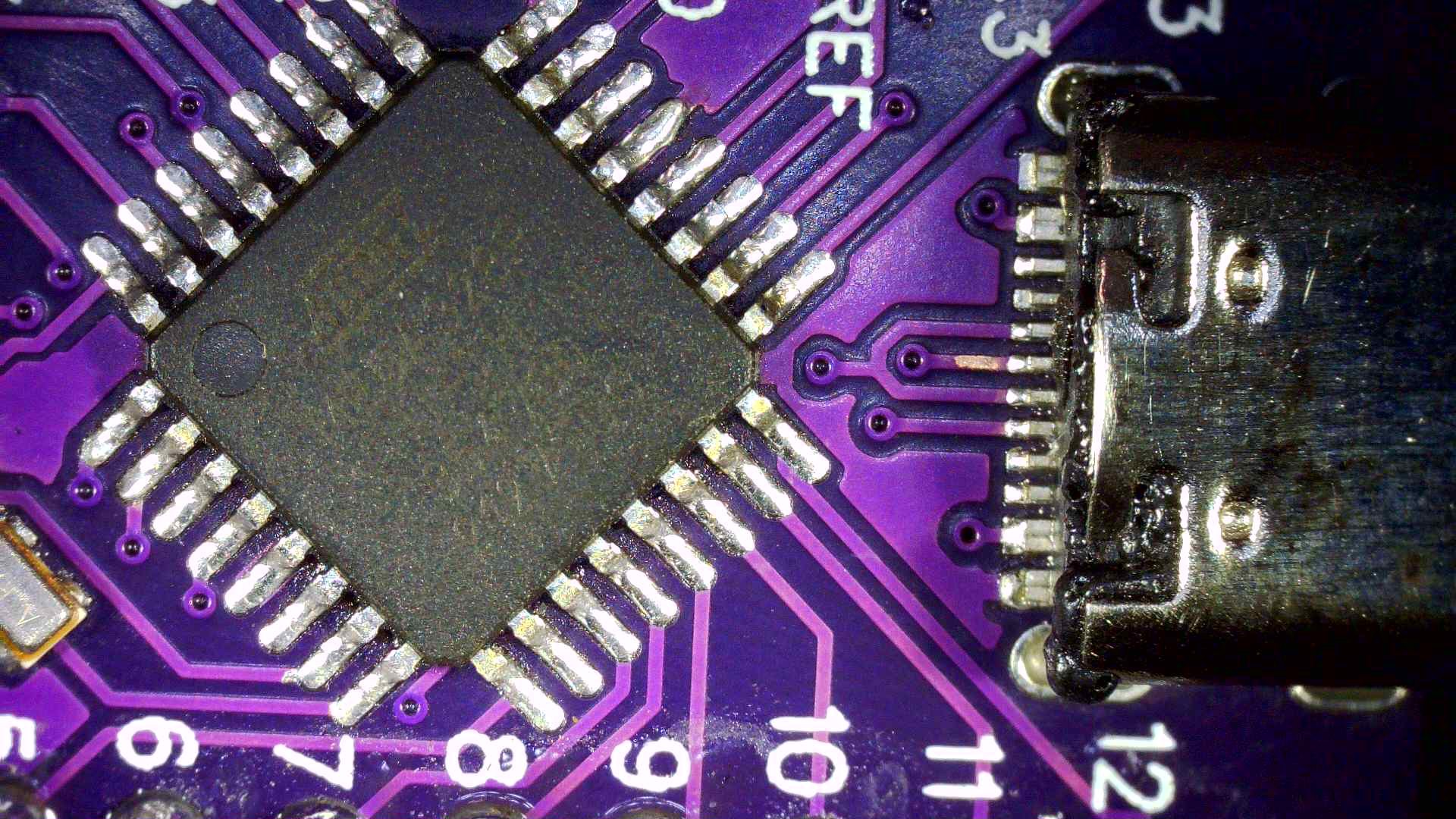
Soldering and assembly:
For now the BOM file of this PCB is not available but here is a mini guide if you can solder all the components on place by hand. PCBWAY also provide stencil service which I tried with this PCB. Just apply solder paste to PCB and place components one by one. Heat the PCB either on cloth iron or through hot solder gun. The size of the components is quite small and it is not easy to hand solder all the tiny components on place properly.
The component’s placing information is given in the image above. You can take reference from this. I will upload the BOM file may be by the end of next week so that you can also use PCBWAY SMT assembly service.
Bootloader setup:
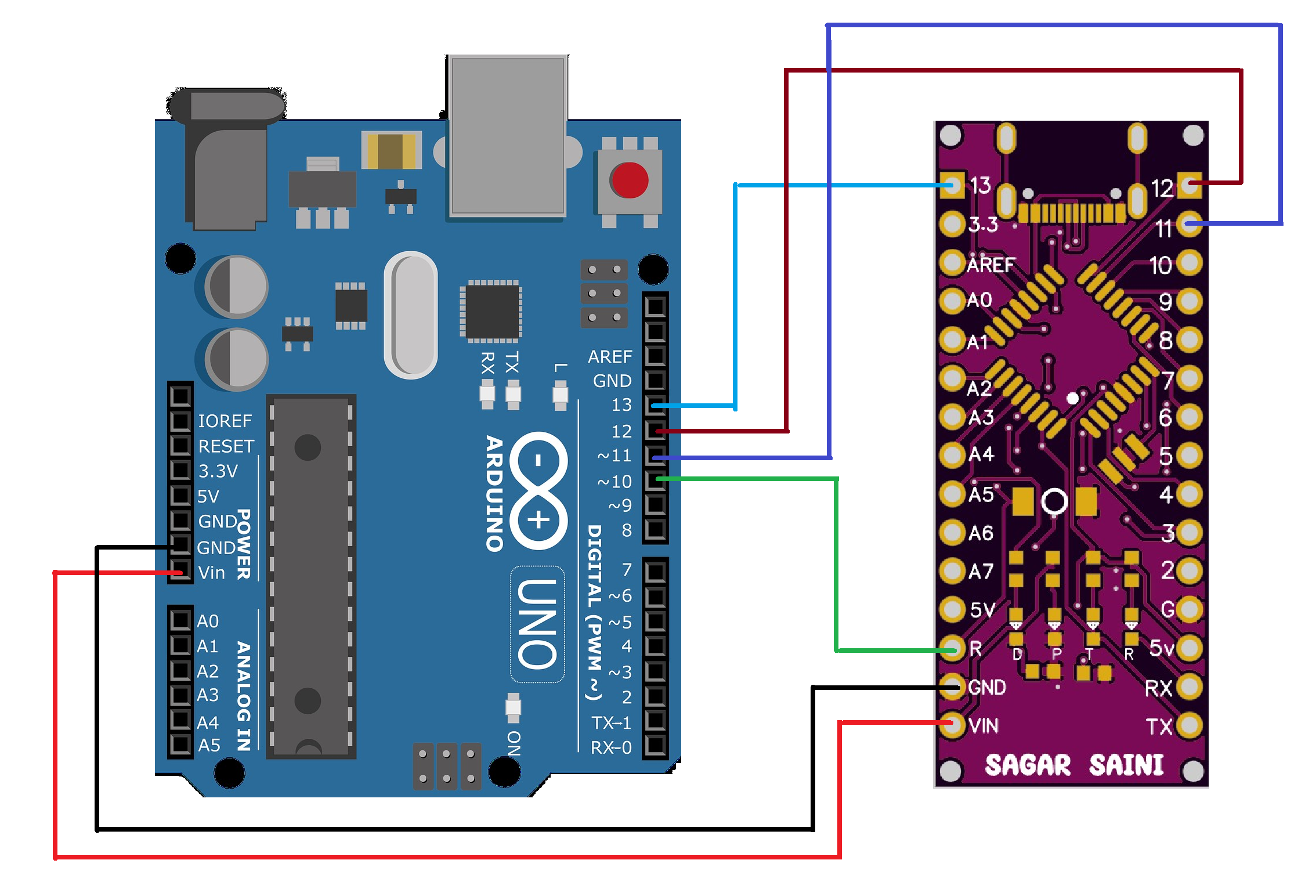
For burning the bootloader we need an extra fully working Arduino board, so that Arduino IDE can use copy the bootloader code from that. Setup the working Arduino board first by uploading Arduino ISP sketch from examples then selecting the programmer as Arduino as ISP. Connect both the Arduino as per given circuit below, select the board (Arduino UNO) right COM and hit burn Bootloader.
This will burn a small code inside the Atmega328p which act as a device id for that device and it becomes easy for Arduino IDE to upload the code by identifying the device signature. You can burn Arduino UNO bootloader in this also if your working board is Arduino UNO.
 Lithium ION
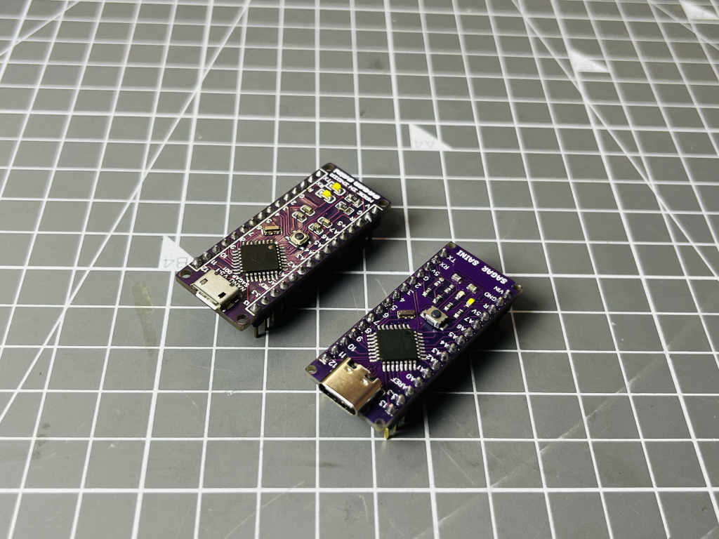


 Sagar 001
 ElectronicABC