0%
0%
The Bipolar Junction Transistor RF Mixer
The Bipolar Junction Transistor (BJT) is your garden variety transistor.
This project tries to workout how to design a BJT mixer.
 agp.cooper
Become a Hackaday.io member
Already have an account? Log in.
Just one more thing
To make the experience fit your profile, pick a username and tell us what interests you.
Pick an awesome username
hackaday.io/
Your profile's URL: hackaday.io/username. Max 25 alphanumeric characters.
Pick a few interests
Projects that share your interests
People that share your interests
 (source:
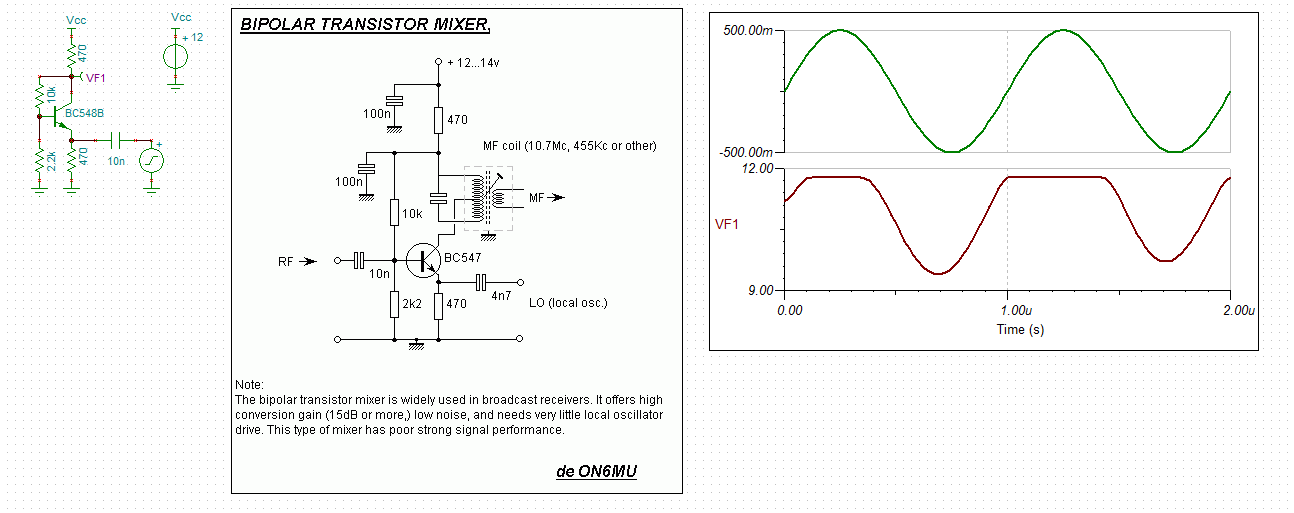

 michal777
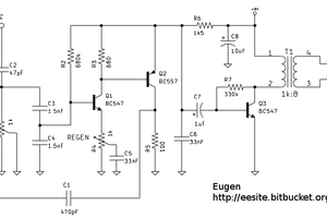
 Clyne
Clyne
 Lithium ION
what you use to simulate this mixer ?
i need something similar but for FM?