eGuidezhan
Supplies
- 1.Arduino Nano (other Arduino-compatible boards will work)
- 2.USB cable (compatible with the Arduino board)
- 3.Breadboard
- 4.Male-Male Jumper Wires (6)
- 5.HW-494 Metal Touch Sensor Module
- 6.HW-480 Red/Green 2-Colour LED Module (common cathode)
- 7.220Ω resistors (2)
Step 1: Know What a Sensor Is
In the realm of electronics projects, sensors act as vital components, serving as the sensory organs that connect and perceive the external environment. When applied to LED electronics projects, the human body itself can function as a natural resistor, allowing the device to be activated or operated simply by touch. Familiar instances of such electronic components can be found in smartphones, where different actions or outcomes are achieved by interacting with the touch screen through pressing or altering current resistance. In everyday life, two commonly encountered sensor types are capacitive touch sensors and resistive touch sensors.
Capacitive touch sensors primarily consist of two conductive layers: a sensing layer positioned beneath the touch surface and a control layer situated at the rear of the sensing layer. These layers are separated by an insulating material.
When a capacitive touch sensor is at rest, indicating no touch on the surface, a capacitance is formed between the sensing layer and the control layer. The magnitude of this capacitance depends on the distance between the layers and the characteristics of the insulating material.
Upon touching the touch surface, the conductive nature of the human body generates an additional capacitance between the sensing layer and the user's finger. This added capacitance alters the total capacitance between the sensing and control layers. The touch sensor detects this capacitance change and converts it into a touch input signal.
To measure the variation in capacitance, the sensor applies an alternating current signal. By monitoring changes in the frequency and amplitude of this AC signal, the sensor can ascertain the touch location and intensity. This information is then conveyed to the device's controller, enabling appropriate responses to the touch input.
Similarly, resistive touch sensors also consist of a sensing layer and a control layer, separated by an insulating layer.
A resistive touch sensor remains idle when the touch surface is untouched, with the resistance between the sensing and control layers maintaining a constant value.
When a user touches the touch surface, the contact area between the sensing and control layers changes, leading to a modification in the electrical resistance between the two layers. Applying pressure at the touch point enhances the contact between the conductive layers, resulting in a decrease in resistance value.
Resistive touch sensors detect changes in resistance by passing a small current through one side of the sensor and measuring the voltage on the other side. Upon touch, the sensor identifies the altered resistance value, which is then transformed into a touch input signal.
The measured resistance value is converted into a digital signal by the sensor, which is subsequently transmitted to the device's controller. Based on the received signal, the controller determines the touch position and intensity, allowing for appropriate operations to be carried out accordingly.
Step 2: Wiring Connection
int redPin = 2;int greenPin = 3;int sensorPin = 4;boolean val = 0;void setup(){pinMode(redPin, OUTPUT);pinMode(greenPin, OUTPUT);pinMode(sensorPin, INPUT);Serial.begin(9600);}void loop (){val = digitalRead(sensorPin);Serial.println(val);if (val == HIGH) { digitalWrite(greenPin, HIGH); digitalWrite(redPin, LOW);}else { digitalWrite(redPin, HIGH); digitalWrite(greenPin, LOW);}}The project code comes from TechSparks, if you are interested in this project, you can go to their blog site for more detailed information!
 hIOTron
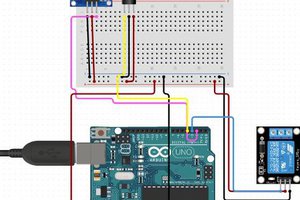
 Tony Kambourakis