Intro
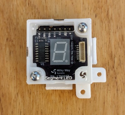
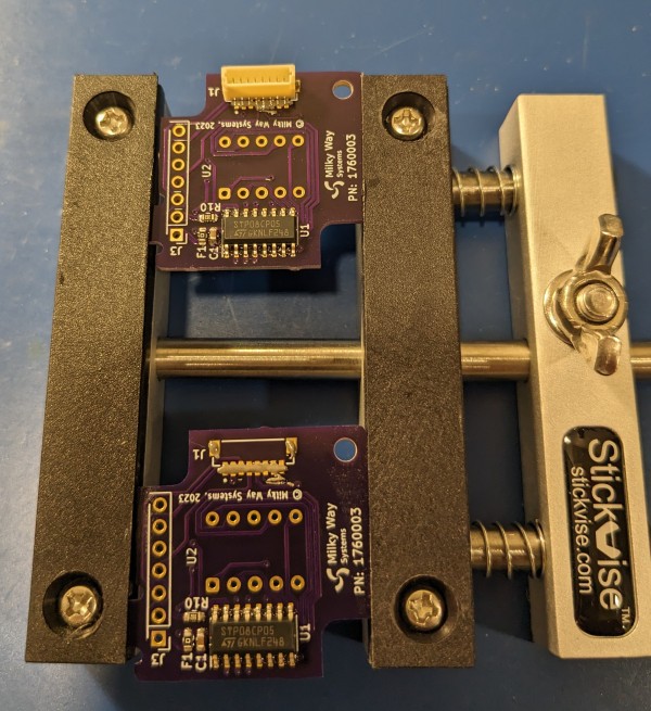
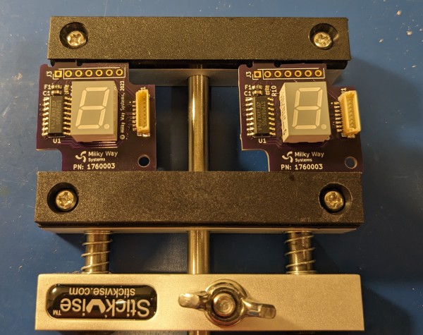
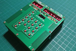
Command Modules allow you to quickly add a user interface to your prototype. They're made up of individual blocks, each with a switch, potentiometer, display, or other user interface part. This particular one has a display and driver with a serial interface.
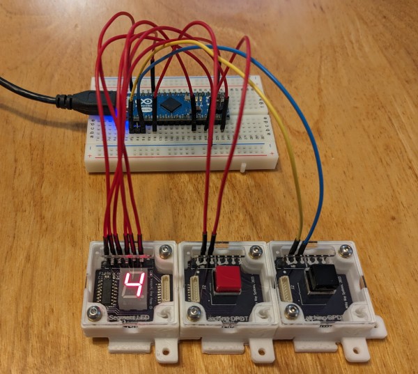
You can use the blocks individually or attach several together. Below, I have a few hooked up to an Arduino on a breadboard. The blocks each have a pin header at the top for connecting jumper wires.

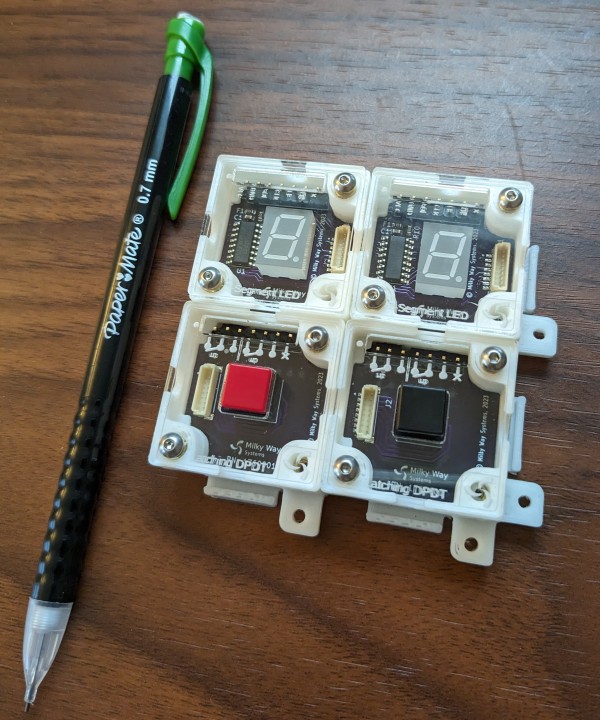
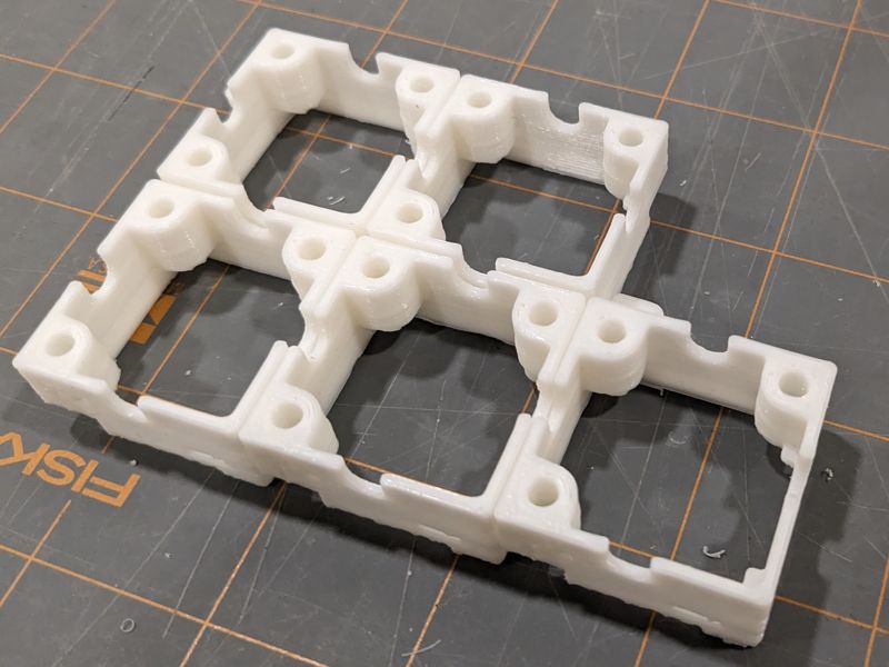
For more complex interfaces, you can attach Command Modules in grids.
How it started
Many prototypes around these parts have a hardware user interface of some sort. One recent example is the Op Art project that I built for HaD's op amp competition. It's a circuit for plotting Spirograph-like patterns on an oscilloscope. Before getting into a PCB and all that, I built a prototype on a solderless breadboard.
The breadboard prototype needed a switch and two dual gang potentiometers to adjust the patterns. Neither part fit well into the solderless breadboard. I resorted to tacking leads onto the potentiometers and left them dangling off to the side. I left the switch out altogether, and just selectively re-arranged wires on the breadboard. Needless to say this was quite a mess.
I’ve run into this issue before and never found a great solution. The closest might be those big breadboards with built-in switches, LEDs, pots, and so on, which are popular in classrooms. However, they take up lots of space, and also lack more useful parts such as rotary encoders, and also more esoteric parts like the dual gang potentiometers that I needed for Op Art.
There's got to be a better way. So that's how this project got started. It's my attempt to build a system for prototyping hardware interfaces. Ideally you should be able to position switches, pots, displays, and so on how you want, then quickly connect them to your prototype.
Design Objectives
- Expandable - Able to scale from one element (e.g. switch) to any number of elements
- Reconfigurable - Ability to change the order or position of the elements
- Easy to connect into a circuit
- Ability to add labels - e.g. label describing the function of a switch
- Visually appealing
System Design
This system is made up of individual blocks called Command Modules Blocks (CMBs). Each CMB is a square block containing a user interface component such as a switch or potentiometer. You build up an interface by connecting CMBs together to form rows, columns, or grids of arbitrary size.
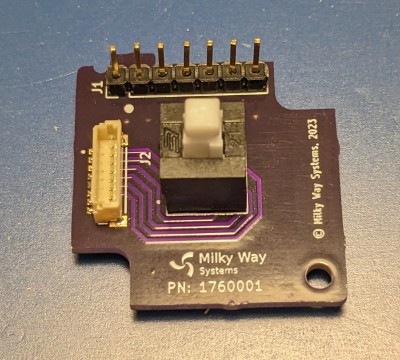
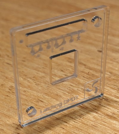
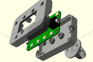
Once the interface is assembled, you can connect it to a circuit in one of two ways. The simplest is using the pin header that's accessible through the top cover of each CMB. For a neater look, the CMBs also have an internal connector and wiring slots. This allows you to keep wiring behind the CMB front panels.
Mechanical Design
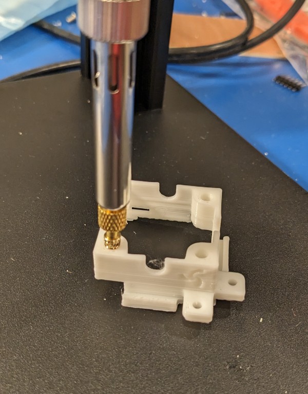
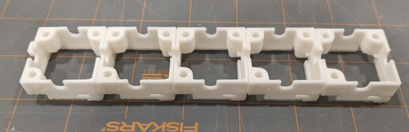
At the core of a CMB is a part that I call the frame. It's what holds everything together and allows the blocks to attach to each other. The frame is sized to fit a variety of elements, such as switches and potentiometers, but is no larger than it needs to be. It also provides mounting features for a circuit board on the bottom and a cover on the top side.


 SUF
SUF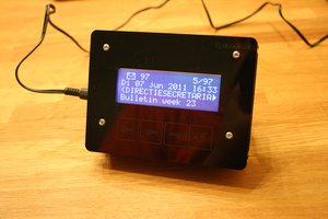
 Springuin
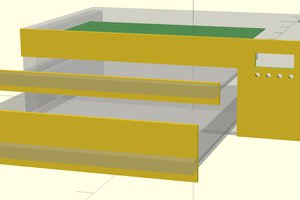
 leumasyerrp