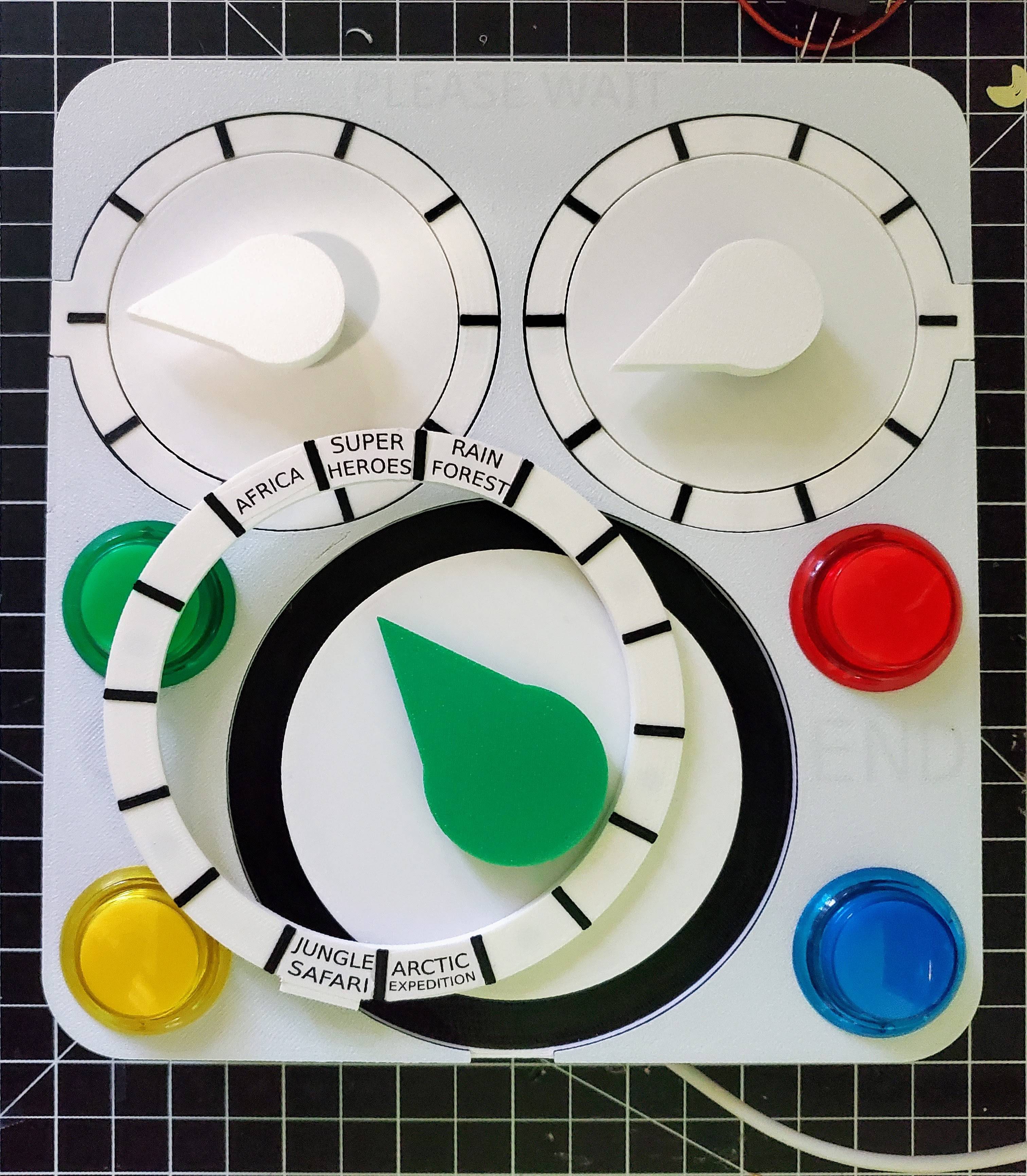
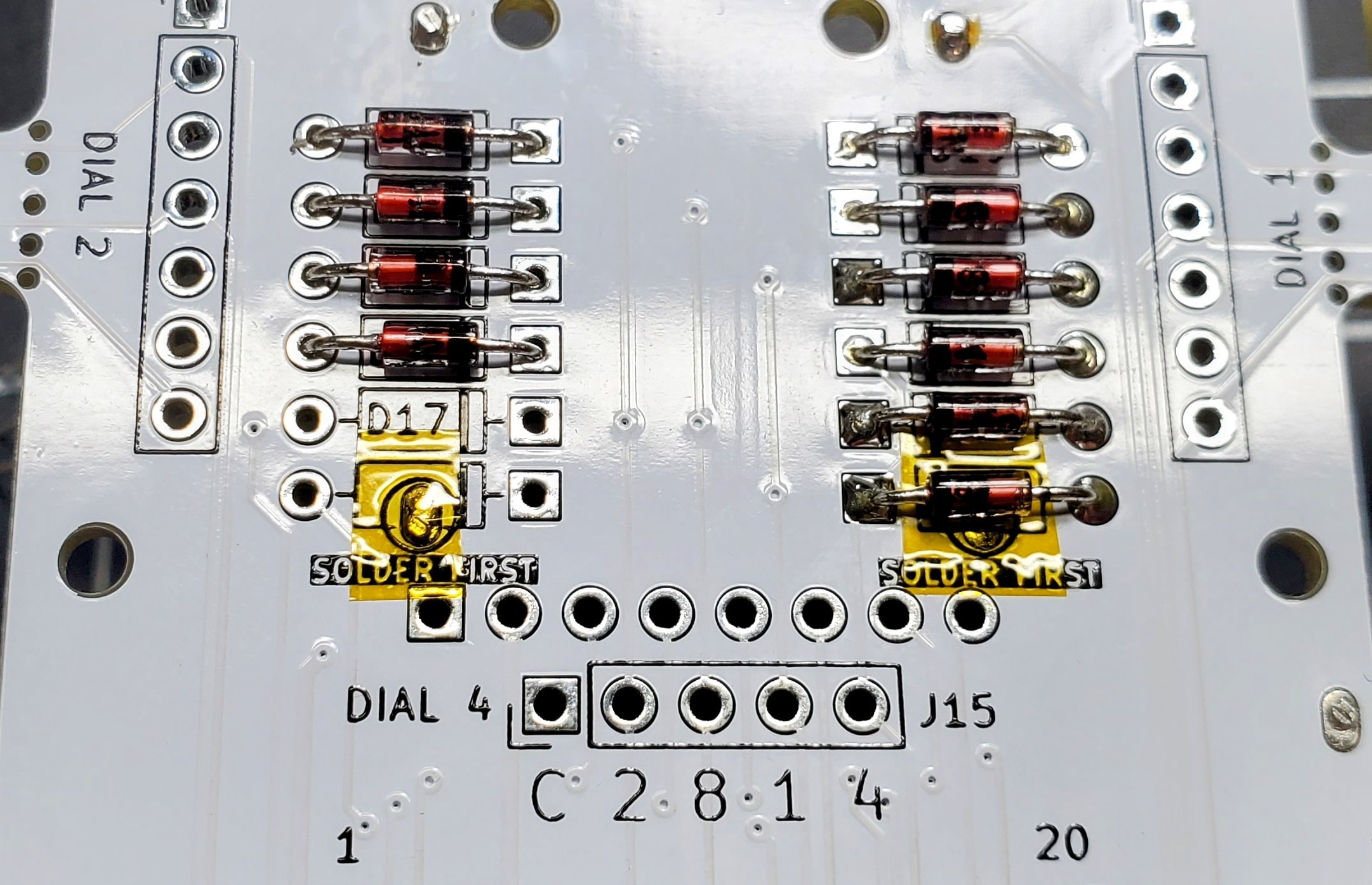
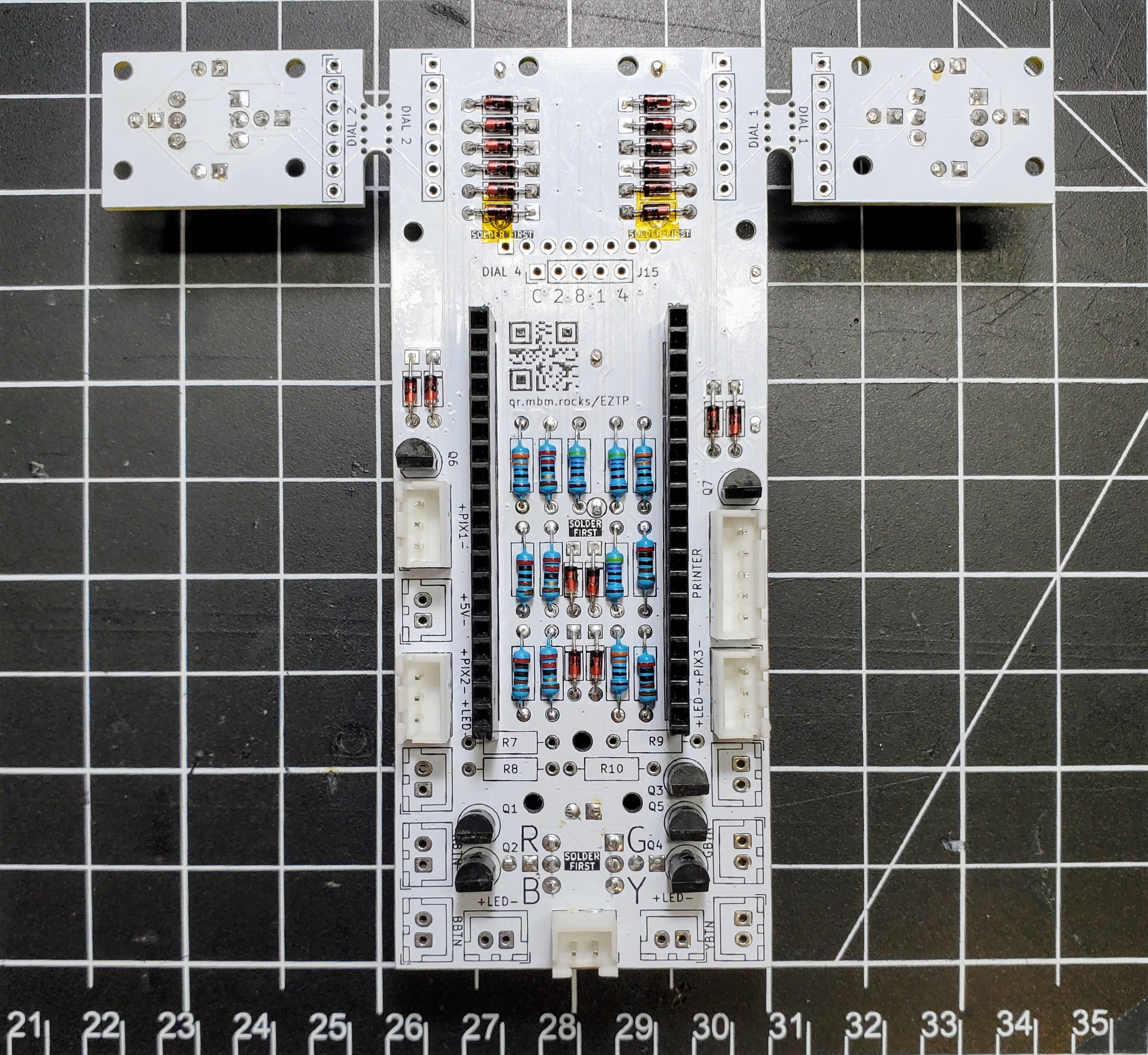
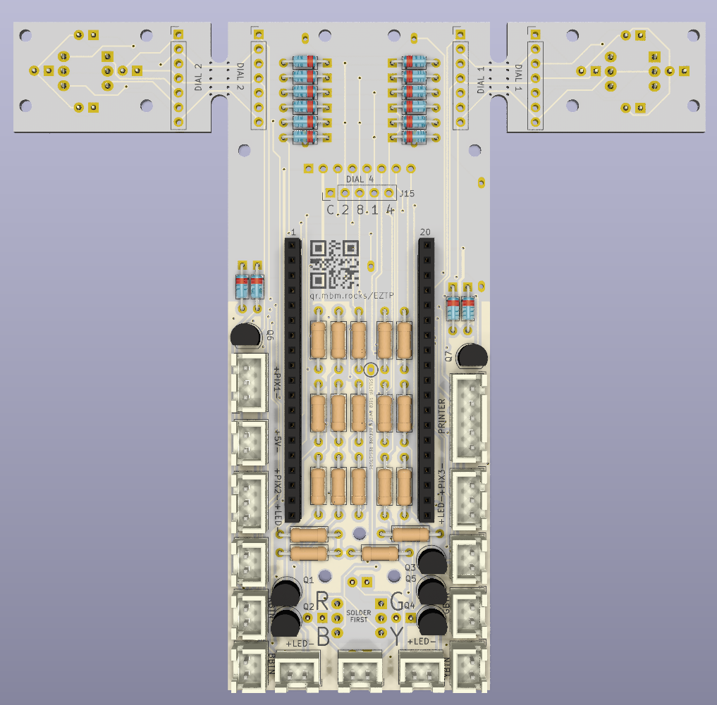
• Front Panel Wiring

    Jon10/19/2023 at 03:56 0 comments

    The arcade buttons are attached to the front panel and wont move so I wired them directly to the PCB without using connectors. The wires are taped to the button housings to make sure they stay out of the way when the front panel is installed.

  • The Front Panel

    Jon10/18/2023 at 00:25 0 comments

    The PLEASE WAIT, GO, and END text is hidden from the face when the LEDs are off. To get this effect, the first layer is printed solid and then subsequent layers have a void where the text is. To get better contrast, the filament color was changed to black after two layers of white.

    To keep the exterior of the whole thing mostly white, I switched the filament color back to white after the letter silhouette layers.

    The centers of the dials are printed separately as an insert to allow for different colors for the center and the void when the interchangeable rings are removed.

    The insert screws into the face plate frame and then the PCB is attached to the insert with standoffs to protect the glass on the magnetic reed switches. Once the insert is installed the magnets for the rings can be glued into the recesses.

  • PCB Assembly

    Jon10/17/2023 at 04:42 0 comments

    The PCBs arrived and everything went together smoothly.

    The dials had to be installed first because the top/bottom LEDs were slightly too close to the switch body and wouldn't let the dials sit flush with the pcb when installed first.

    The Magnetic Reed switches have a solder joint under two diodes and needed to be installed before the diodes. I covered the joints with Kapton tape even though the diode body shouldn't be conductive.

    After the reed switches were installed, I added the resistors, transistors, and microcontroller socket.

    I clamped the PCB to the table to make sure the cable plugs were completely flat. I only installed sockets for connections going to things mounted to the body. The buttons and LEDs attached to the face plate will be wired directly to the board.

  • Initial Test Fit

    Jon10/01/2023 at 05:46 0 comments

    I printed the full front plate and inserts at full size to test fit the interchangeable dials, magnets, and buttons. The hidden text is also easily visible with just ambient backlighting and even through the green filament I used for the test prints. I printed partial test pieces for the printer insert to make sure everything else fits well.

  • Do I need a PCB?

    Jon09/20/2023 at 21:27 0 comments

    I wasn't sure if I was going to hand-wire this or have a PCB made for it, and after mapping things out I decided that a PCB was certainly necessary. There's over 250 solder points which would have been nearly impossible to do cleanly by hand.

    The front side of the PCB has only the rotary DIP switches and some LEDs to light each dial up to indicate when it can be used. Beyond those components, it is flat and should be easy to integrate into a housing. The PCB is sized to fit within the 180mm × 200mm faceplate that can be made on a standard 3D printer, however the upper dials can be snapped off and relocated via extension wires to allow for any size/shape of dial configurations. There is also an unpopulated header for a 4th dial that can be optionally added.All
    All external connections are spaced to accommodate JST XH connectors which are common on arcade buttons and other devices like the mini receipt printer, or wires can be directly soldered.