Close
0%
0%

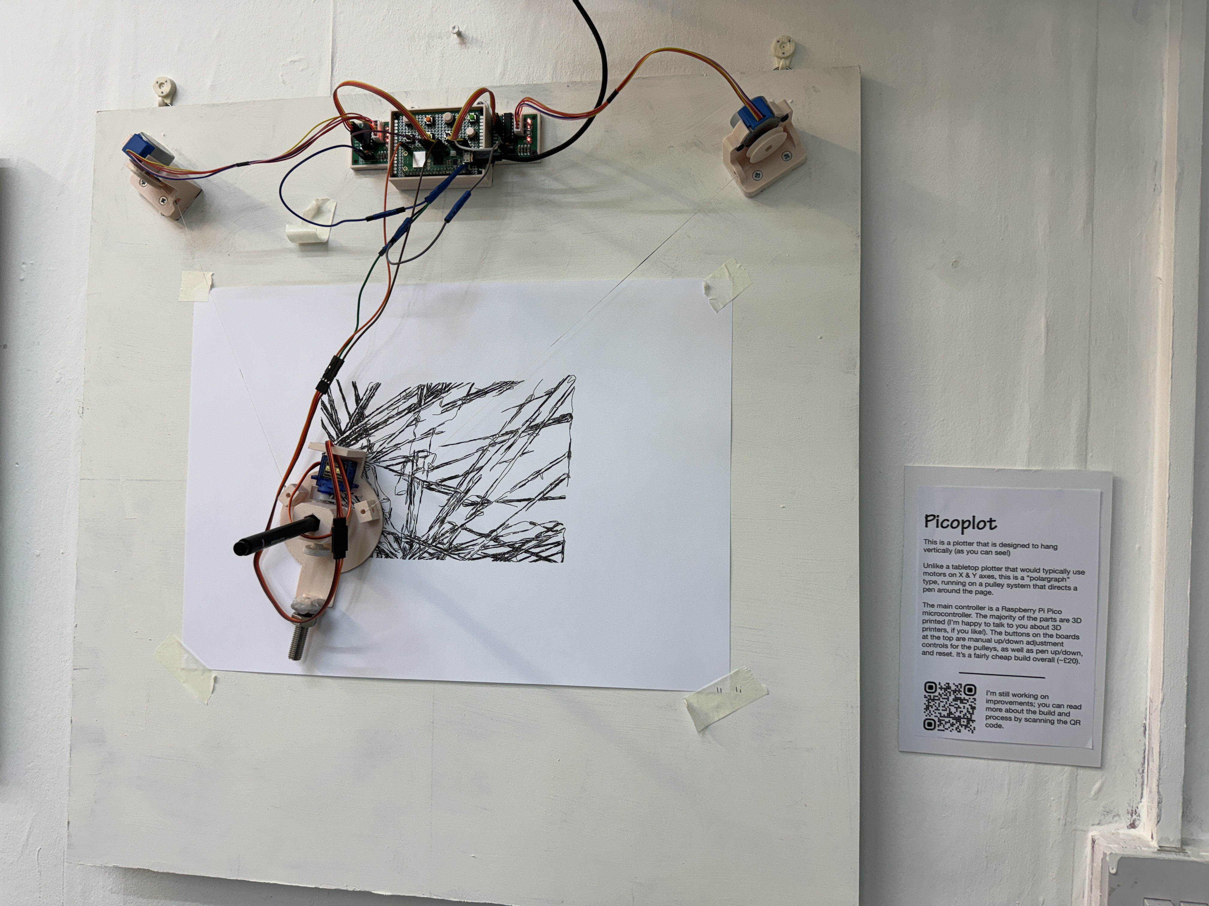
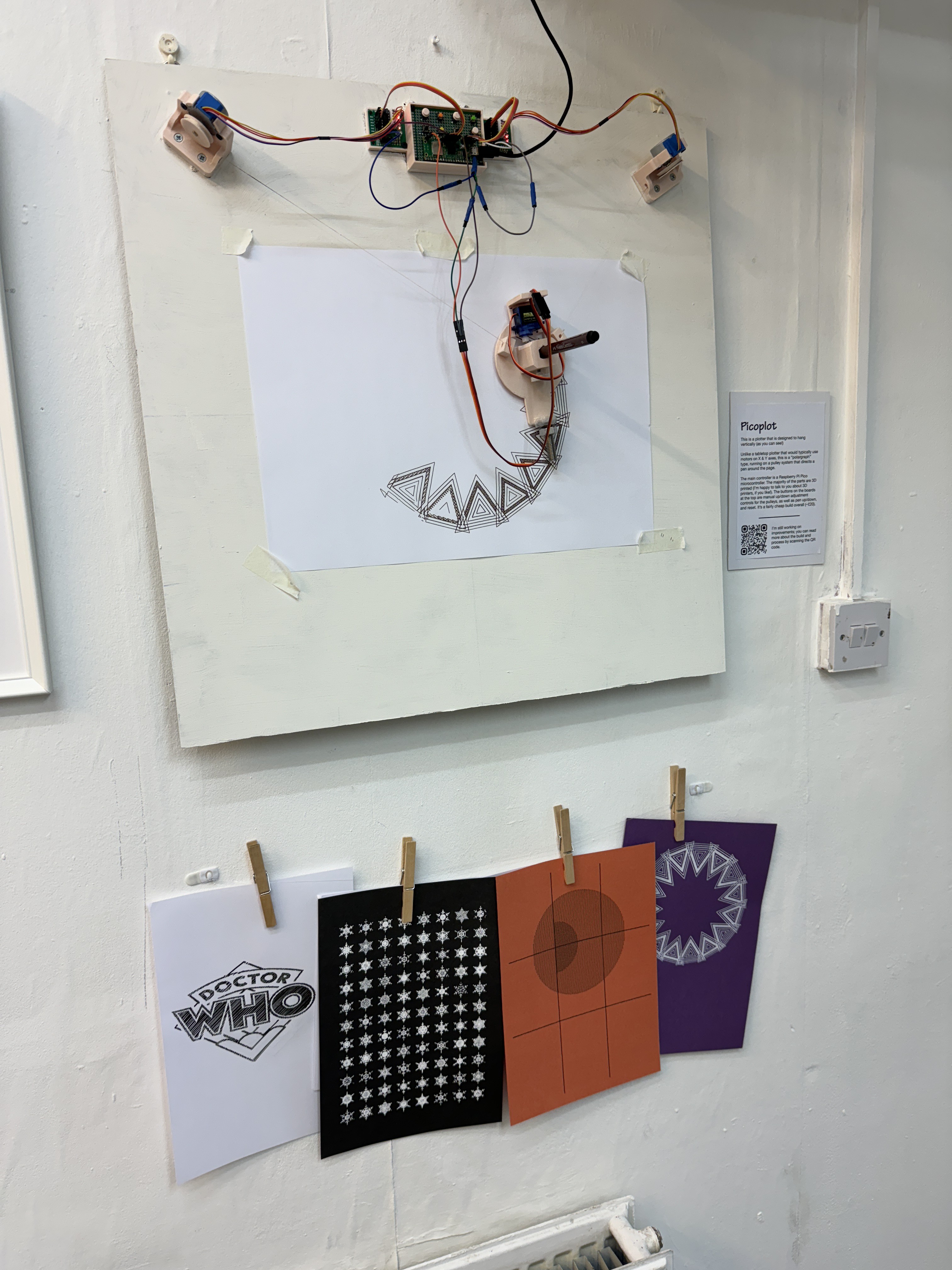
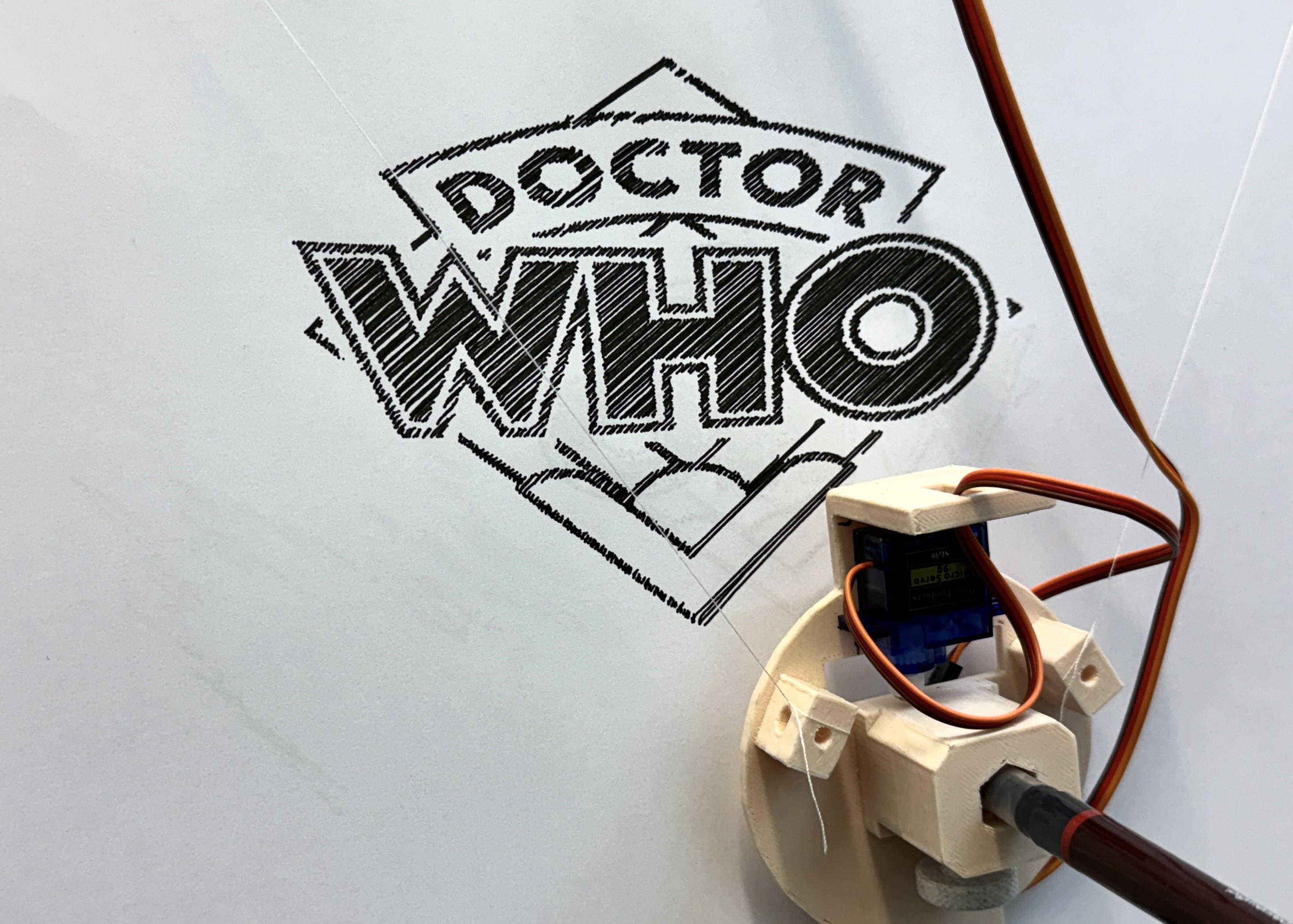
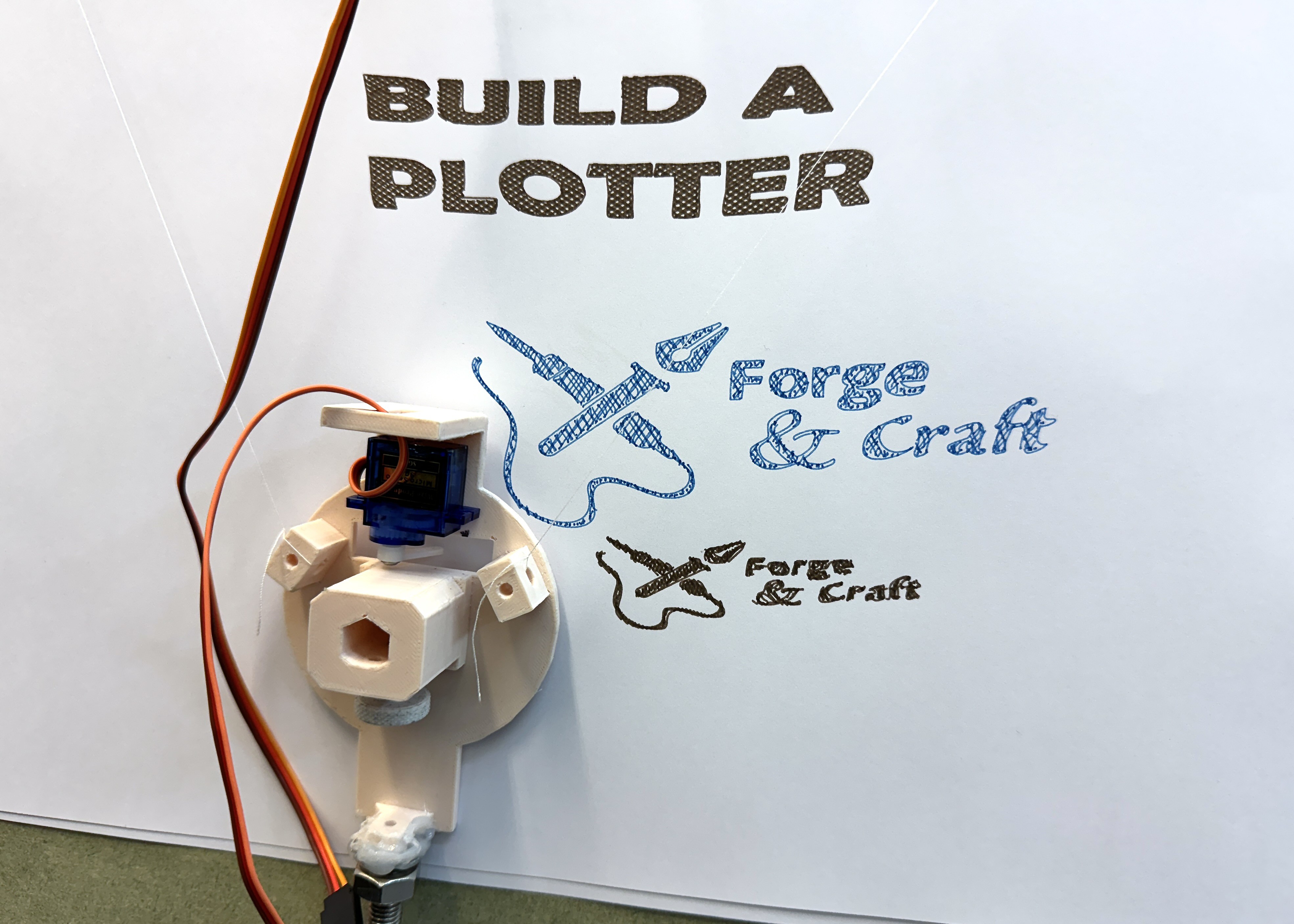
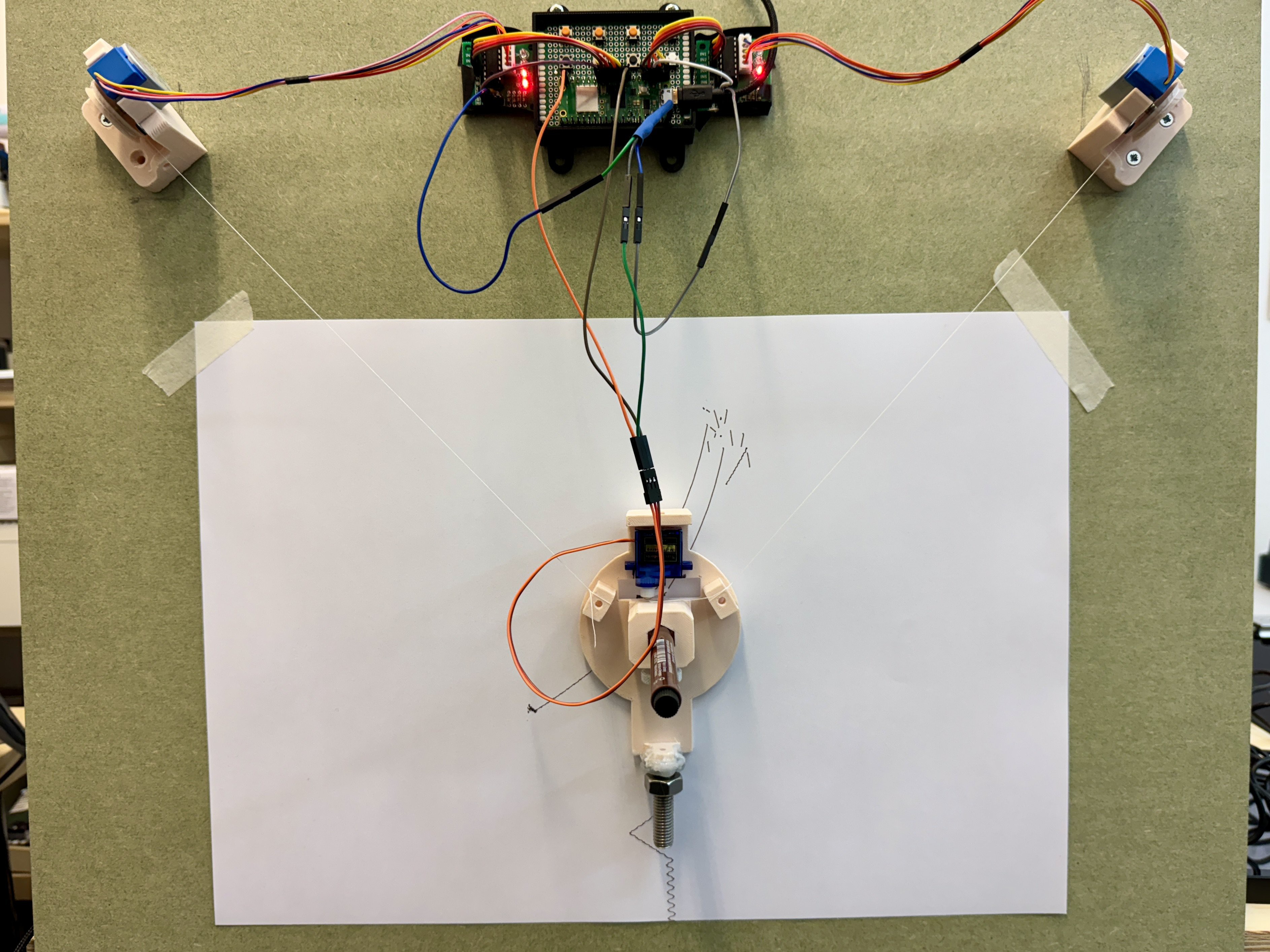
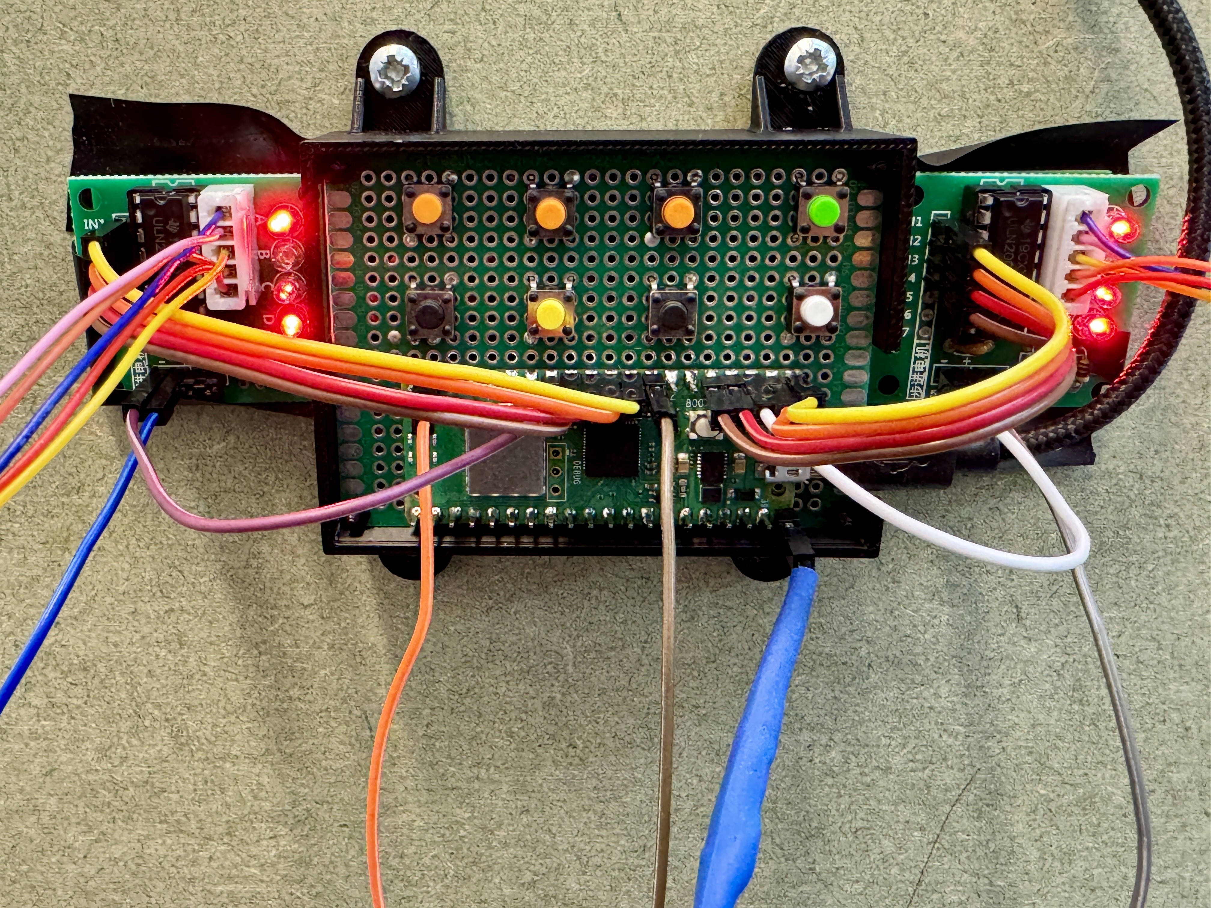
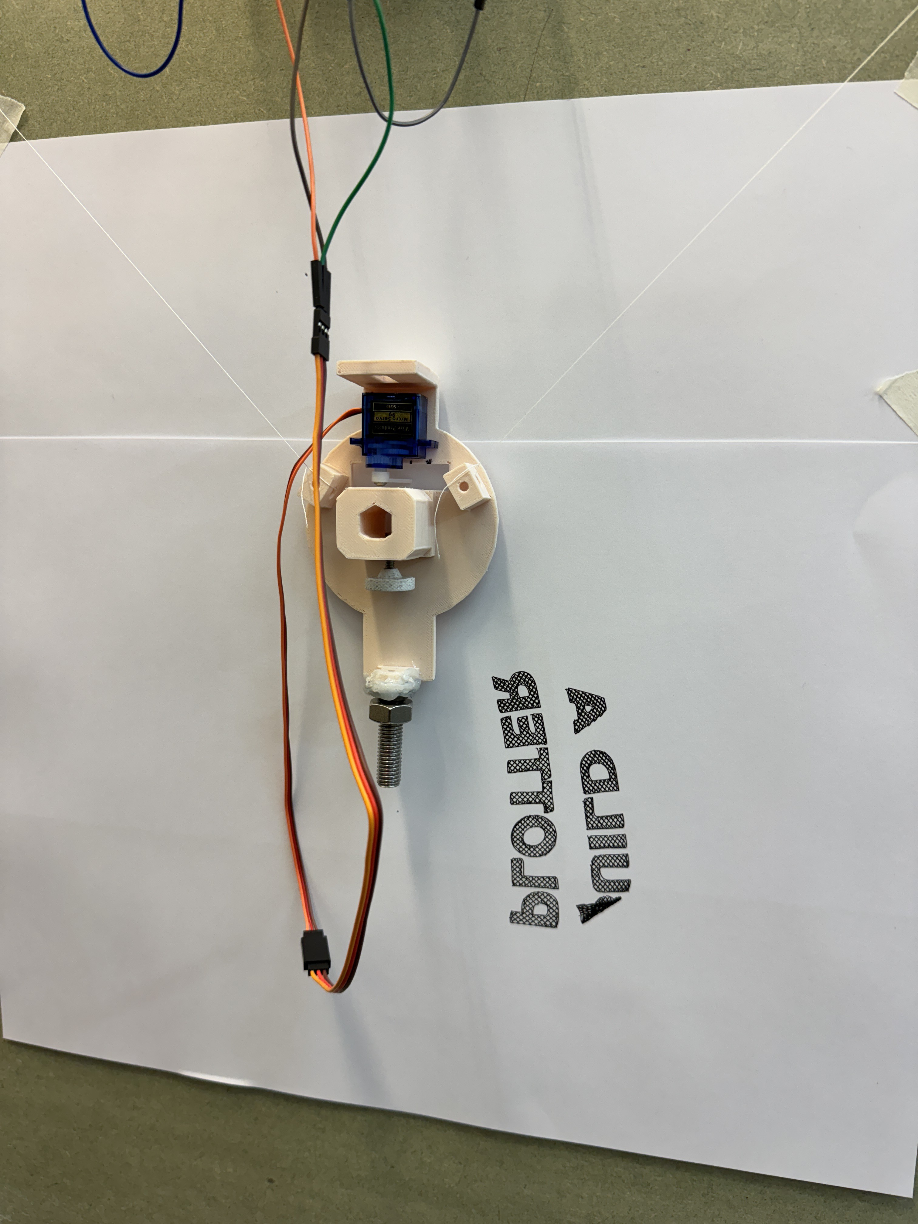
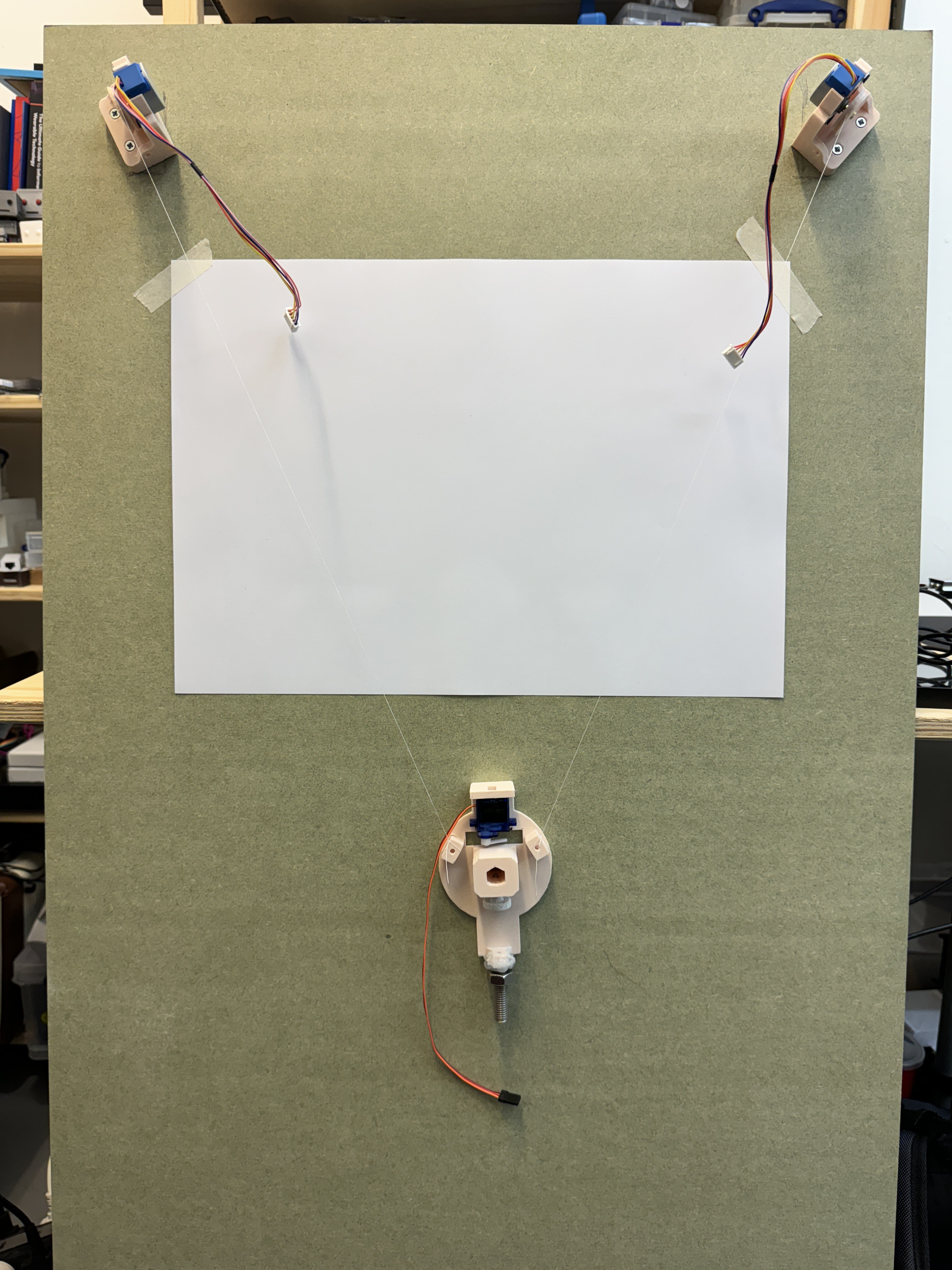
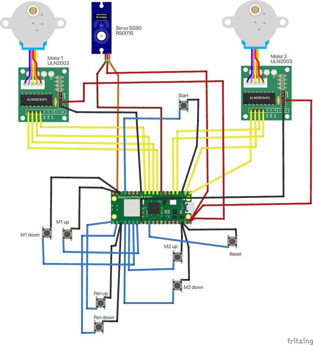
Minimal Pico Vertical Plotter

Building and improving a Raspberry Pi Pico-based, wall-hanging vertical plotter.

Similar projects worth following
This project contains the development log and additional information about vertical plotter designed to hang on a wall, using a Raspberry Pi Pico W as the controller.

The plotter was originally described with basic (but incomplete) details in the May 2022/issue 55 of HackSpace magazine, as a fork of a cheap Arduino-based machine bought online (that did not work!).

Here’s a chronicle of my efforts to identify the missing information from the article, to improve the build, and to update the code.

The story of building a vertical plotter.

  • 1 × Raspberry Pi Pico W
  • 1 × 50 x 70mm protoboard (could be any suitable size, this just about worked for my Pico + buttons)
  • 8 × simple pushbuttons
  • 1 × 9g basic Servo motor
  • 2 × 28BYJ-48 5V Stepper motor + ULN2003 driver board

View all 14 components

  • Real-world lessons and adjustments

    Andy Piper11/18/2023 at 12:34 0 comments

    We are part of Wimbledon Art Fair this weekend, and the plotter (which I have named "Picoplot" for the sake of having a title!) is hanging just inside the studio door, as a nice way to draw folks in. Blinky lights and moving robots!

    I've painted the MDF back board as the original greenish colour was a bit jarring on the wall, and I also "upgraded" the cotton lines for the gondola to an extra strong thread (and also made them a bit longer). We put a fishing line across underneath the plotter to hang pieces from - although several of the plots in the picture below are from the AxiDraw on the table across the studio.

    I thought I'd write down some real-world lessons learned.

    • I marked the thread where it goes onto the pulleys with a Sharpie so that I could easily get the pen back to the centre of the board... it was a good plan in principle, but the ink bled along the thread so it is not as accurate as I wanted.
      • as an aside, multicolour / layer plots are a bit challenging when the pen is off-centre.
    • The plotter is hanging above our radiator (the existence of which, to be honest, was a large factor in our choice of studio!)... this means that the pen tips have dried up on a couple of occasions and I've had to start over.
    • There have been some issues where the wires for the gondola have become tangled around the pen or otherwise become too taut, so the gondola has ended up at an angle with the pen unable to touch the paper.
    • The practical limits of where the pen can travel are becoming more apparent. To try to keep the pen more level, I added an additional nut to the hanging bolt (a handy thing that Ben had in his design I've forked from, the fact that I can just screw on another nut to add ballast is super useful!)

    Finally, the reliability has proven a bit hit-and-miss. I'm not certain of the cause - I think loose wire connections are part of it (I'll likely switch to soldered connections in place of the Dupont connections after the show), but I also noticed some static discharges happened when I came near the radiator a couple of times. I don't particularly want to hide the circuit inside a sealed box as this is currently a nice talking point, but if that is the issue then I might work more on the 3D printed elements to make it prettier (and hopefully, less susceptible to external static discharge).

  • Printing my own parts

    Andy Piper11/07/2023 at 13:18 0 comments

    The project heavily depended on Ben's original article and 3D printed parts including the motor holders and the pen gondola.

    It was never completely clear how the electronics were attached to the board in the original design. I've now merged some other 3D parts together into an "all-in-one" frame that contains the protoboard with Pico W and buttons, which attaches the two motor driver boards on either side. That is then screwed onto the MDF backboard. I also printed off a couple of "feet" that I've glued onto the back of the board along the base, that will hold it away from the wall at a slight angle to give the pen more of a purchase to press against the paper.

    I used Tinkercad to merge the parts, and printed them in the same basic PLA I used for the other pieces. The objects are available on Printables and also in the GitHub repository. I have black nylon standoffs connected to the PCB in each of the four corners that sit on the lugs inside the corners of the box, but it is generally all press-fit into the case otherwise.

    I'm thinking of printing some slightly larger / more obvious caps for the buttons, but that's no more than a nice-to-add.

    For now I'm still going to be driving this via USB serial with a very long extension cable over to my desk, so I'd like to move on to figuring out how to enhance it to receive commands via wifi instead. As mentioned in the previous log, that will wait until after the art show.

  • More progress (and a cool plot)

    Andy Piper11/04/2023 at 19:49 0 comments

    I'm happy with the output right now. I thought the right-hand motor was slipping / behaving inconsistently, but I've re-done the GPIO connections and I think one of those may have been loose previously. One thing I don't yet have fully worked out is the dimensions of the drawings - I've tried resizing in Inkscape, and also providing a larger plot area to the gcodeplot Python program used to convert to gcode, but I'm still not achieving the sizes I'd like.

    As mentioned in a previous update, I've now trimmed the board down to 60cm x 60 cm in size and I'm nearly ready to put it up on the wall.

    I designed a new holder for the circuit and motor driver boards, but the first print was a bit too tight so I'll add a few mm and reprint shortly. I also made a couple of small printed "feet" for the bottom of the board so that it will stand slightly tilted away from the wall at the bottom and give the pen a better surface to drop onto.

    From here, I'll also need a fairly lengthy USB cable (at first) since the process to plot is still direct gcode commands over serial. Once the upcoming art show is over, I'll look into ways to have this work over WiFi, to take advantage of the Pico W. 

    One final thing I'd like to do is to set up a way to record the plot process... will have to figure out an appropriate way to mount and point a camera at the whole setup!

  • Firmware tuning - and success!

    Andy Piper11/01/2023 at 13:37 0 comments

    In the previous test, I was getting output, but the alignment and direction was all wrong.

    After several iterations (switching m1<->m2 wiring, and also, diving back into the firmware code), I figured out that the firmware needed to be set up to invert one of the motors.

    #define INVERT_M1_DIR     1 // -1        
    #define INVERT_M2_DIR     -1 // -1

    I also needed to tune the angle for the servo to ensure that the pen was properly lifted. Merged into my fork of the original code.

    There have also been a few annoyances with the wiring (the Dupont cables kept popping apart where I'd extended things so I lost power to one of the motors midway through a plot, for example). Also, motor 2 seemed to be slipping / not moving as smoothly as motor 1... I think I've now resolved that by reseating all of the connections. Lots of tidying up to do.

    CNCjs has worked out well to drive the plotter. For the studio logo, I took an existing SVG, broke it down into paths, used the AxiDraw plugin for Inkscape to add hatching to fill, repositioned the whole thing over the corner of the page (because the plotter expects a centre-aligned image), and used Ben's fork of gcodeplot to output a gcode file that I could use with the plotter. It looks like gcodeplot could actually send the commands directly to the printer, as well.

    I'm happy that I've got to here from the original article and materials i had to hand! There are a number of things I want to work on next:

    Hardware:

    • print a better holder for the electronics. Right now, the ULN2003 motor drivers are barely attached to the board with electrical tape, and keep falling off... not ideal.
    • (possibly) switch to a better thread, or, would fishing line be good here?
    • trim the board to a size that works for the whole setup (I can take off about 50-60cm without impacting the drawing area; I think I'll go to 60, which will leave me with a square 60x60cm MDF board)
    • mount the board on the wall of the studio.

    Firmware:

    • the original, original code had support for reading a file from SD card. I have a microSD adapter board which I could wire up.
    • I have a Pico W here, so I could be accessing it wirelessly...
    • should I try this in MicroPython? that would mean rewriting all of the tricky gcode handling code, which I haven't had to go near so far.
    • so if I have serial, SD card or wifi inputs, I would need a mode switch of some kind to select how the plotter should expect to be driven.

    ... and then if we start thinking about mode switches, I might need to redo the electronics, and then I might want a board that takes a Pico as a controller, with the motor drivers and buttons attached... and hey, I've built a CNC machine. And we are back to "why am I not using GRBL/grblHAL here?". Well, because this is interesting.

    For something that was intended as a learning exercise, I've learned a lot, and have different directions I can go! I'm not marking this as completed just yet, but I count it as "mostly done".

  • First test (and more software discoveries)

    Andy Piper10/31/2023 at 12:15 0 comments

    I printed a small case for the protoboard, but need to design something that will also hold the motor drivers, currently attached via tape...

    While looking for more GCode sender alternatives to UGS, I also stumbled across Inkcut. I had an installation issue where it needed a newer version of enamlx than my Python version supported, but got that resolved. Looks really nice. I'm sticking with CNCjs for the most part.

    First runs involved some adjustments, for example, the thread holding the gondola slipped from the bobbins a couple of times, but I've now threaded it through the hole in the 3D printed holder so that's less of an issue.

    It is definitely doing something mostly right, but I need to make some changes to the motor wiring - looks like I have things reversed here somehow. I think it's potentially as straightforward as having M1 and M2 swapped around, but super annoying as I've tried to be very attentive to wiring as I've proceeded with this build.

  • Software shenanigans

    Andy Piper10/27/2023 at 22:36 0 comments

    So close to getting things running. I am waiting on a longer cable for the pen servo (I've tested with some Dupont connections but want something a bit better before running it in place on the hanging plotter).

    I've been trying to get the computer to talk gcode to the plotter.

    In the original article, Universal GCode Sender (UGS) is the recommended and documented way to get things going. The firmware code is written so that when the start button is pressed, the Pico outputs a couple of lines of information to the serial connection, identifying as a build of the GRBL firmware for CNC machines. The idea appears to be that given those two lines of information, UGS should say "OK, that's a machine running GBRL", and then you should be able to hit the "play" button to send the gcode file across.

    I've spent a fair bit of time trying to follow Ben's description in the article, with the latest version of UGS on macOS, and it just will not open a clean and complete connection to the board. I've been as far as checking the debug logs from UGS; putting a build of grblHAL on another Pico and trying to get UGS to talk to that (UGS doesn't properly support grblHAL at the moment, AFAIUI); and comparing the serial output and conversation sequence between UGS and other CNC machines, based largely on blog posts and reports from GitHub issues and wiki descriptions.

    It looks as though UGS sends $I followed by $$ followed by $G to check on board capabilities.

    I've added a small amount of  GRBL command handling to the firmware. I have the Pico respond to these commands in a meaningful(ish) manner, but the connection never seems to fully resolve to a point where UGS will let me hit play. This is fair, because the controller is not running full GRBL, but it is a bit annoying that the recommended software cannot be persuaded to act as a simple sender and pipe gcode over serial.

    (I believe the controller is doing its job, though; I've pasted in some of the gcode commands from one of the sample files at the serial prompt in the terminal, and had the servo and stepper motors start to move around, indicating that they are being driven by the commands)

    Basically, either my setup is behaving differently to Ben's system from the HackSpace article; UGS has been updated since May 2022 (very likely); or, something else. There's a possibility it's an OS-specific thing, too - I'm trying this on macOS Sonoma; the article appeared to use Windows (?); I do have a Linux machine available as well, but I haven't tried on there as yet.

    I've tried bCNC (a Python GUI); but for some reason that is not even wanting to find my USB serial port. As an aside, it also looks absolutely terrible / barely readable in dark mode on macOS.

    I finally hit potential success with CNCjs, an Electron-based GUI, which is letting me connect... which I installed using homebrew. I did have to make a small tweak (specifically, turning off system quarantine for the app via xattr -d com.apple.quarantine /Applications/CNCjs.app) to get it to run without complaints. When I have the last piece of wiring, I should be able to try one of the test plots.

    In the end though, this minimal approach may be too little, and it may be that I should switch across to a more functional (grblHAL?) firmware of some kind, assuming that I'd be able to figure out how to have that drive a hanging wall plotter...

  • Firmware setup

    Andy Piper10/27/2023 at 22:16 0 comments

    Getting the firmware (code on the Pico) into shape was one of the more interesting parts of this project.

    The code shared alongside the HackSpace magazine article is incomplete, forked and modified from a repo that is primarily in Chinese, and over a year old.

    I've created my own fork of Ben's fork, and inside that right now there's a pico-w-build branch which is getting commits as I get to grips with the code.

    Quick run-down of changes and approach:

    • I primarily code for the Pico using MicroPython (and I may come back to this project with some MicroPython another day), this is based on Arduino, so to get started I needed to install the RP2040 / Pico W support for the Arduino IDE. The repo didn't contain specific instructions, but I've noted that I needed to install the board support by adding https://github.com/earlephilhower/arduino-pico/releases/download/global/package_rp2040_index.json to the Arduino Boards Manager preferences.
    • The repo contains various libraries, I chose to install the TinyStepper driver "properly" via the Arduino IDE.
    • I moved the .ino file containing a datestamped filename up out of the WallDrawGCODERP2040 sketch directory, to avoid compilation collisions.
    • I chose to step through the whole of the source code and translated the Chinese versions of the comments using Google Translate, to help myself to understand the control flow.
    • As noted in the previous log, I added the Fritzing schematic to the hardware folder.
    • I added a small piece of code to switch the onboard LED on when the start button is pressed for long enough to move the Pico from "buttons control the pen and gears" mode (how it starts up), to "ready to receive gcode commands" mode.
    • I made a couple of adjustments to hack in some additional "pretend" GRBL command parsing. As noted in the original article, the initial serial output from the Pico is supposed to trick the GCode sender software into thinking the plotter is running GRBL (a CNC firmware), I extended this very slightly in an effort to get things to work (see the log on Software support); in the end this has probably been a bit of a waste of time so far.
    • This was all rebuilt with the latest Pico W SDK / Arduino board support, vs the ~May 2022 .uf2 file supplied with magazine article.

    All of this took a fair bit of build/reset/upload work, with the motors and servo wired to the Pico, in order to confirm that the firmware is good. That's a large part of why I ended up adding the (white) reset button to the protoboard.

    At this stage I'm able to compile and upload the sketch to the Pico W, and also, have the buttons trigger the expected actions (motor 1 & 2 up and down, pen up and down, and switching into GCode command receiver mode). I've been checking serial output using tio, Serial.app for macOS, and Arduino Serial Monitor. Assuming that the code supplied with the article will in fact plot from a GCode file as intended, this means that I'm most of the way there.

    In theory, the final steps here are getting desktop software to talk to the plotter, and having the plotter do something useful.


    I have some ideas for changes to the firmware if I stick with this minimal, sub-GRBL implementation:

    • Ben's repo has notes on a potential use of an SD card, that could be useful
    • Wifi upload of GCode (?? I now think that's a lot more effort than I initially thought, largely because I've now dug into GRBL and CNC software more than I expected to...)
    • Improvements around homing and control
    • (maybe??) MicroPython rewrite, but that will involve having to properly understand the GCode translation into stepper control logic, which I haven't gone anywhere near as yet.

  • Assembling the electronics

    Andy Piper10/27/2023 at 10:47 0 comments

    The electronics side of the project was where I started to hit some bumps in the road from the original article.

    First of all, although the article contains a list of required components, I don't think it's fully accurate. 

    Exhibit A:

    ... so that's 7 buttons, then 🤓

    I've mounted the Pico (W) on a protoboard and laid out 7 buttons, with a bit of colour-coding since I had some coloured ones to hand - orange for the "up" buttons, and green for "start". After a bit of testing with the firmware, I also added an 8th button as a broken-out reset for the Pico.

    I also decided to make a diagram to help me to sort out the wiring, since the original project didn't contain one (although it does helpfully explain which pin connects to what, as above). I created this using Fritzing, which needed me to track down parts for the Pico W and the motors. The Fritzing sketch is inside my fork of the original GitHub project, on the pico-w-build branch.

    A possible future revision could include a nicer, possibly custom-designed PCB to contain the Pico, the buttons, and maybe even with space for the ULN2003 motor drivers to be attached so that it's an all-in-one control panel. Just an idea.

  • Getting started - 3D printed parts and components

    Andy Piper10/26/2023 at 20:09 0 comments

    Back in April 2023, I built a Brachiograph, which set me off down a rabbit hole around pen plotters and mechanical drawing machines. I subsequently purchased an AxiDraw SE/A4 (and then upgraded it with a coreless servo).

    I've been wanting to build a vertical plotter for my studio wall for a while, and remembered an article from Ben Everard in HackSpace magazine issue 55 (now available online).

    I printed the 3D parts from Ben's Printables page, and ordered the various parts I needed - specifically I needed to order a pair of stepper motors. I already had a Raspberry Pi Pico W - which was an upgrade on the Pico that was used in the original piece, and got me thinking along the lines of updating the project to support wifi uploads for plots further down the line. I also already had a spare servo from the Brachiograph project, and a selection of push buttons.

    The 3D prints were pretty straightforward - loaded straight into Bambu Studio and printed on the Bambu X1C in basic PLA. Two mounts for the stepper motors, and a gondola (that Ben had borrowed from elsewhere) for the pen. I realised that I wanted to be able to adjust the pen slightly more comfortably than directly adjusting a screw so I added another part that I found on Printables to make it easier to turn the bolt.

View all 9 project logs

Enjoy this project?

Share

Discussions

Similar Projects

Does this project spark your interest?

Become a member to follow this project and never miss any updates