 Samuel Comeau
The protocol seems similar to the WS2812 LEDs, but is different enough that I feel it is worth sharing. I don't know the actual IC or part that is being used. It looks like a standard 5mm led with a flat face similar. It is very similar in appearance to the Owire LEDs that SparkFun sells, but that is were the similarities end.
Electrically the tree is wired using a +5V and GND wire. The signal is carried over the positive line. It starts at 5V and dips to about +1.8V. Each part of the tree has its own plug. I'll call these sections. Each sections has four strings of LEDs that can be controlled separately for 12 total strings.
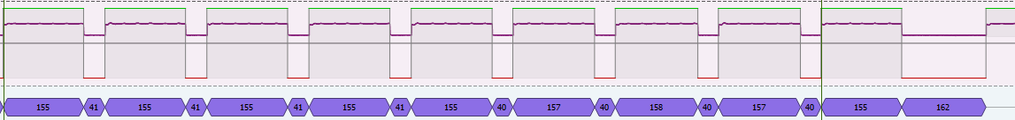
The protocol is a pulse width protocol. It consists of packets of low logic pulses 40, 80, or 160us in length. A pulse of 40 indicates a zero, 80 is a one and 160 is a stop bit. These low pulses are separated by high pulses of about 155us. So that a pulses that make 100b would look like:
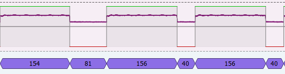
Each transmission begins with a start bit of 1 followed three bit string address with LSB first. These bits denote the string that is being controlled. Mine were 1 (100b), 2(010b), 3(110b), 4(001b). The next 8 bytes are the red value for the string, again with the LSB first. Then Green, Blue and White.
An example
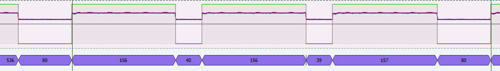
The next eight bits read:
0000 0000 so red is 0x00.
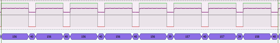
Next:
0000 1111 so green is 0xF0. (Don't ask me why not 0xFF)
Blue is also 0x00.
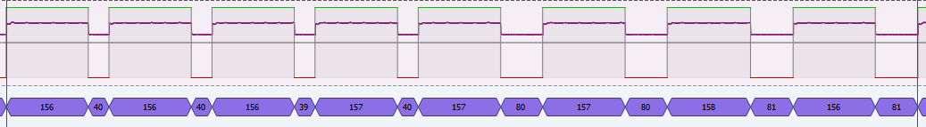
White is the last byte so it ends with the special stop bit:
As of now I don't know how to actually use this information. I'm looking for a way to be able to pass through the original signals, but be able to add new ones with an Arduino. Potentially, that is going to involve a transistor in series with the +5V/signal line.
Hope this helps anybody else looking into this stuff. If you have questions let me know and I'll see what I can find out.
Methods
To measure the signal I used the Hantek DSO2C10 which sells on Amazon for about $200. I triggered the signal and saved it as a .csv. I then imported it into PulseView. From there I tried several standard decoders, but didn't manage to make much headway. I was able to overlay the pulse widths as seen on the above images. Then it was possible to tell that the different symbols existed. I then capture a signal that should correspond to green. That was how I was able to determine the color order.

 Yann Guidon / YGDES
 LordGuilly
 Myles Eftos
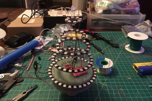
 Jorj Bauer
This is interesting! I'm also reverse engineering my devices to visit to the
https://sportdisney.com/rodrygo/