 Joseph Eoff
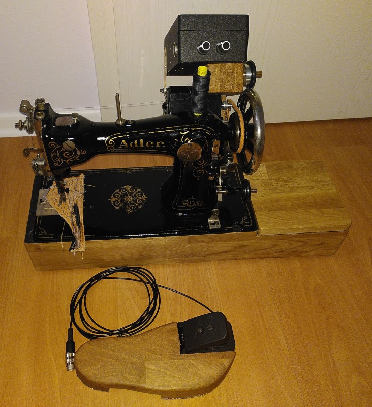
I use an Adler class 8 sewing machine to sew projects out of leather and Naugahyde.
The Adler was not made for that kind of thing - it was built for speed. Punching through a few layers of leather doesn't bother it - I can sew leather with it with nothing more than one finger turning the balance wheel.
There was never a hand crank for the Adler as there was for many vintage sewing machines of the same age. The Adler was made for professional use. It had a treadle table.
My Adler has to get by with an aftermarket sewing machine motor. Its table is long gone. Folks in Germany like to "upcyle" sewing machine tables as decoration. The machines are then usually disposed of as junk - my Adler was a victim of someone else's "upcycling" project.
Leather is normally sewn with rather long stitches, The combination of a fast sewing machine and long stitches means that the article you are sewing runs through the Adler very fast - too fast for me, to be honest.
To make my Adler easier to use, I came up with the Bigfoot controller.
Bigfoot has a Hall effect go-kart pedal mounted on a custom floor pedal. I find the commercial controllers uncomfortable - I have to bend my foot too far up to use them. The Bigfoot pedal is made to be comfortable - most of the motion range is below flat footed.
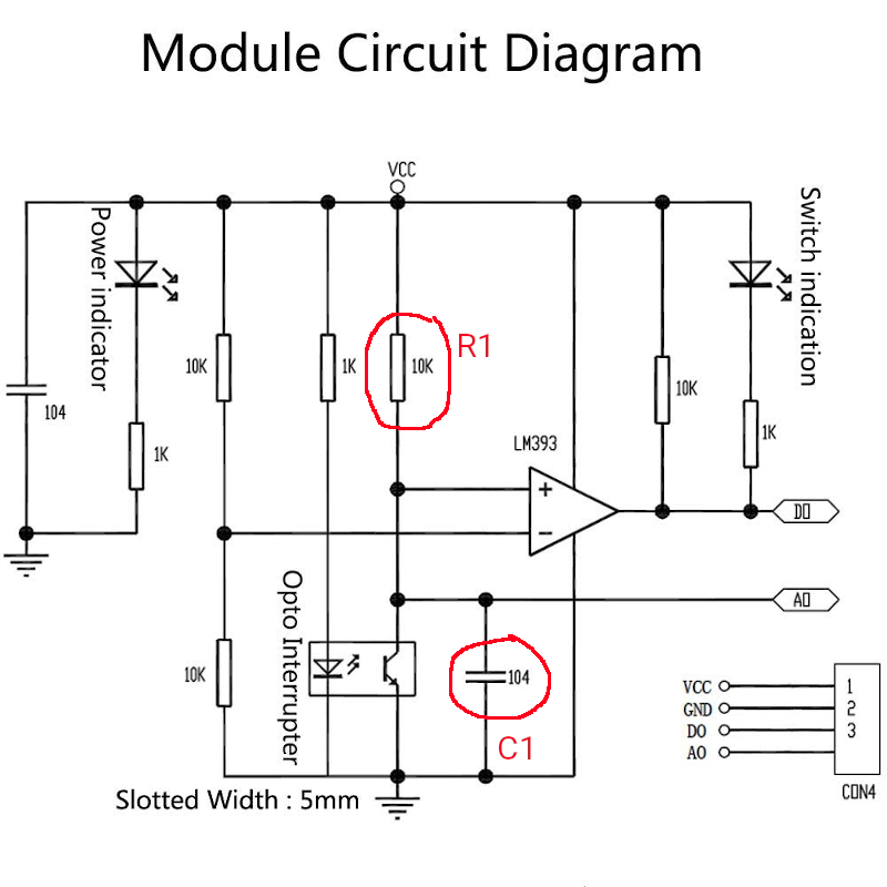
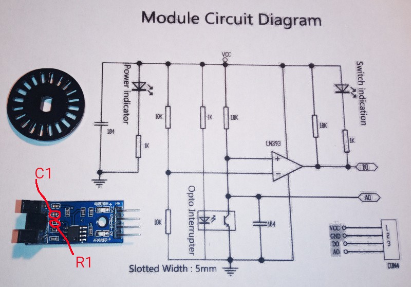
The controller has a photointerrupter with a slotted wheel and a friction drive to pickup the sewing machine speed. It is mounted on the motor such that the pickup rolls on the handwheel.
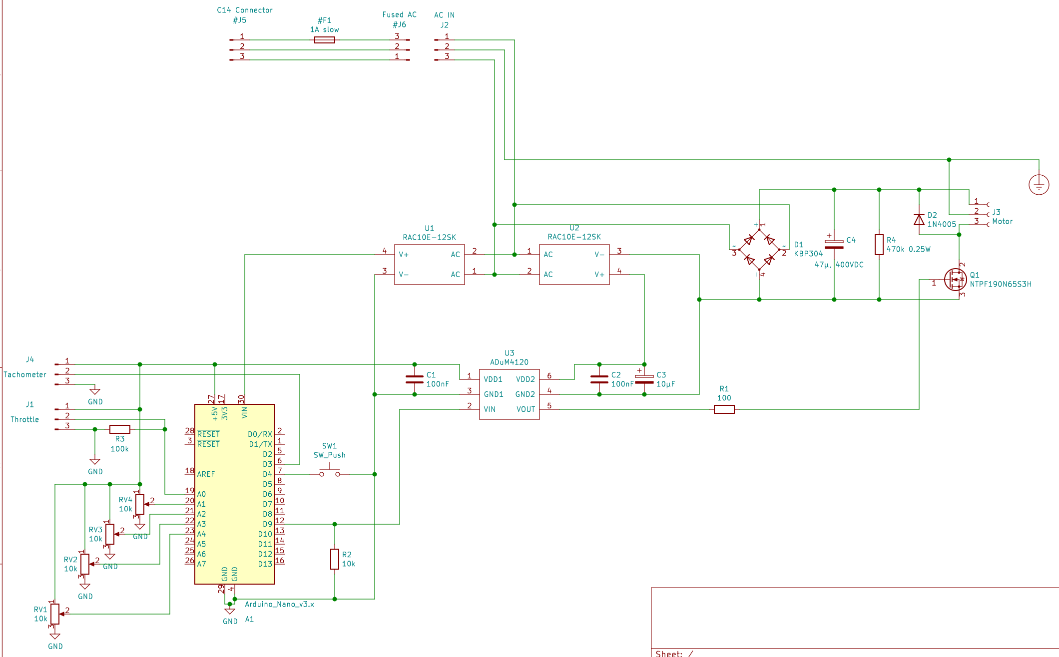
Inside the controller is an Arduino to read the motor speed and the foot pedal and to generate a PWM signal to drive the motor.
There's an isolated MOSFET driver to allow the Arduino to drive a MOSFET controlling 300VDC. Typical sewing machine motors are universal motors designed to be driven on line voltage. Full wave rectified 230VAC gives you 300VDC - and the universal motor is just as happy with that as it would be with AC.
The Arduino runs a PID controller to maintain the set motor speed.
Since I find manually tuning PID controllers to be really difficult, there's a pushbutton "tune PID" function built in. Raise the presser foot, unthread the machine, press the button, wait while the machine runs the speed up and down for a few seconds, all done. The PID coefficients are automatically stored in the Arduino EEPROM.

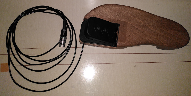
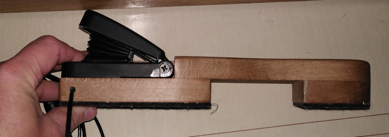 That's a beech wood foot with a "heel" and a "sole" to support it. There's a layer of thick felt underneath it all to keep it from scratching the floor.


 Dillon Nichols
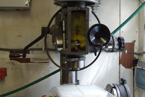
 Sci
Sci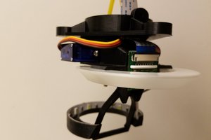
 Daren Schwenke
 Matthew Potter
Hello, Paul.
I am indeed using the "gotPulse" to guard against reading from the "pulseTime" array while the ISR might be writing to it.
"SlapMotor" has two use cases:
1. When starting from a dead stop, "SlapMotor" gets things rolling. Sometimes the motor stops on the edge of a slot. Without that blind slap, the first pulse either comes too soon (impossibly short pulse time) or not at all (the first PID output isn't enough to get it rolling.)
2. At low speed, there may be a "wobble" at the edge of a slot. This also results in an impossibly short pulse time. The slap forces the motor past the wobble.
A fancier encoder isn't needed. There's a lower limit imposed by the material being sewn. If the needle moves too slowly, the leather will "grab" it and not let go. The setup I have now will get me below that limit. For thicker stuff, you must move just a bit faster. I can cover that with the low speed adjustment knob.