 Nikos Katsaros
Let’s see the equipment we used for the purposes of this project:
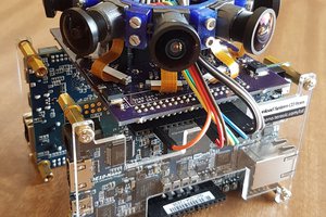
- Zedboard development kit
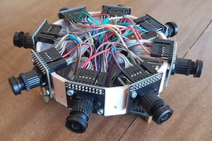
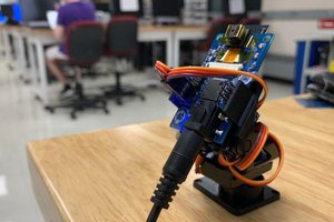
- OV7670 camera module
- Petalinux 2015.2
- Vivado and SDK 2015.2 (following this compatibility guide)
- Ethernet Cable

This is our project Block Diagram

You can find the instructions on how to establish a connection via Ethernet between your PC and a Zedboard running Petalinux on chapter H and I of this post by embeddedcentric.
Let’s now begin explaining the hardware part of this project which code and Petalinux boot images are available here.
The Hardware

First of all we modify the processing system according to the bring up guide for petalinux.
Now to the cameraIp module. We use some of the code of this project by Mike Field and with some additions we managed to add the functionality for the camera to take snapshots. We basically removed the vga part of the code, created the snapshot module and also we modified the top module according to our current specifications. All this modules were packaged in an Axi-4-Lite Ip to work with the processing system. The control signals and the captured image were used in the Axi bus and the camera function signals were made external so as to be connected to the pmod pins of the Zedboard.
The logic part of this Ip works like this:
- The control signal of the arm processor arrives
- The camera freezes and a snapshot is stored in a Bram of the Ip with the dimensions of 640×480 in 8-bit format.
- At every access of the data from the processor, the hardware converts the pixels format to 24-bit(the client uses a 24-bit format to print out the images) and propagates 4 pixels to the output registers.
- After a successful image reading a control signal from the processor arrives and the camera unfreezes.
Now the hardware part is completed and we used these steps to create the hardware platform to run petalinux on it.
The Petalinux Server Software
We created the server application to work this way:
- The server opens a TCP socket and waits for a connection from the client
- When connected it waits for the client request signal to start streaming
- When the request signal arrives, the server freezes the image through a control signal sent to the specific address of the cameraIp interface
- The server reads the image from the cameraIp interface and stores it in a array
- When finished, the image array is sent through the socket port to the client
- Unfreezes the camera and waits for another request to run again from step 3
The Client Software
Finally we created a simple application in python which receives the image from the TCP socket port and renders it in a graphical window. We use the pygame library of python to create the image window and update it with the new images from the socket port.
 Nathaniel Wong
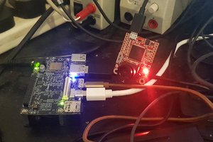
 Adam Taylor
hello,
I am trying project on zedboard.I am using only vivadoo 2018.3 and i got error at bitstream generation.although i added zedboard.xdc file.they shows error as:problem port:clk,config_finished,pwdn,reset,pclk. Please help me to resolve this problem.
Thank you