Component Choice
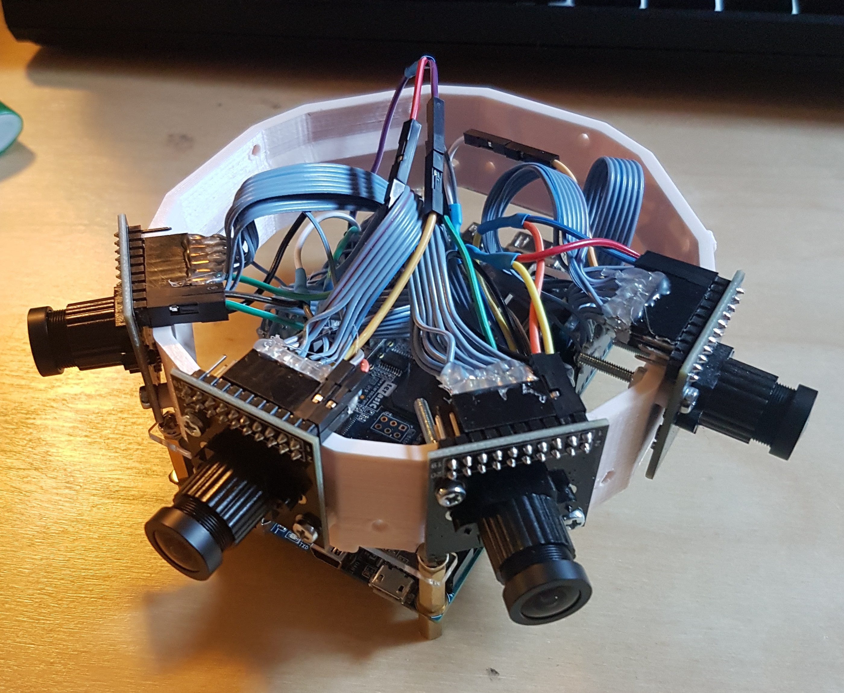
Due to the large number of GPIO ports needed and large bandwidth of data to be processed, this project seemed like an ideal application for an FPGA SOC development board. After deciding to use an Altera Cyclone V SOC for the brains, I narrowed down the choices for a development board and eventually settled on the Terasic DE10-Nano due to its small size, large number of GPIOs, and most importantly, its ample documentation and support.
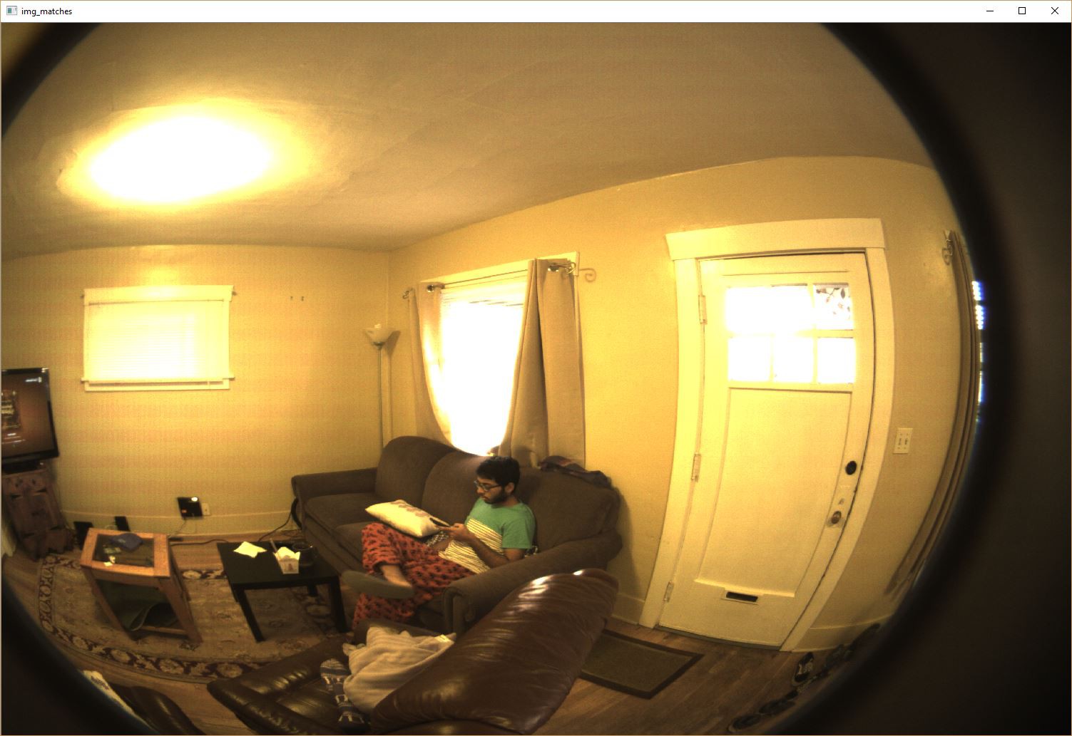
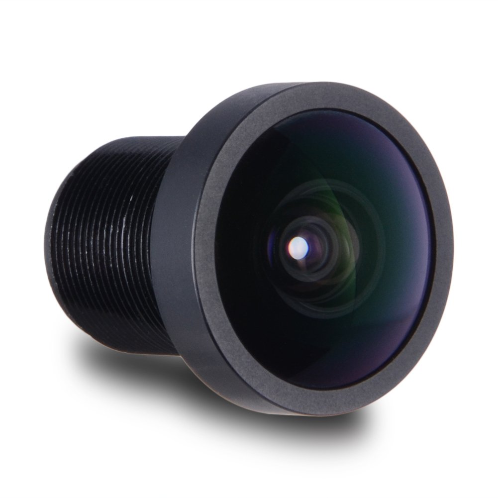
My choice of camera module was easy. The OV5642 is cheap ($25 on Amazon), has good resolution, and has a decent amount of online documentation and drivers available. In addition, it uses the publicly documented Digital Video Port protocol rather than the secret MIPI protocol that is used by most camera modules.
Implementation
My planned datapath for photos will be as follows:
- FPGA implements parallel data receiver from camera
- FPGA writes data from camera to DDR3
- ARM running Linux and OpenCV reads frames from DDR3
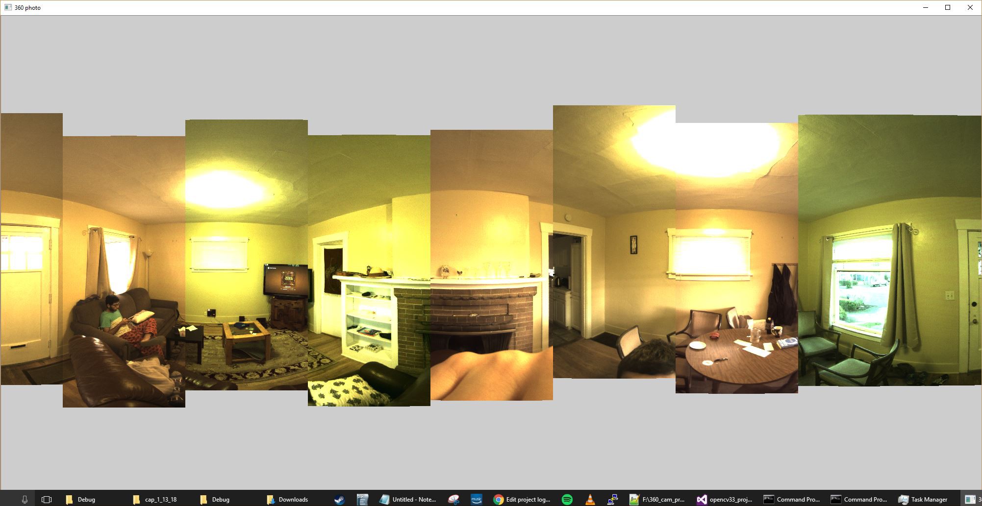
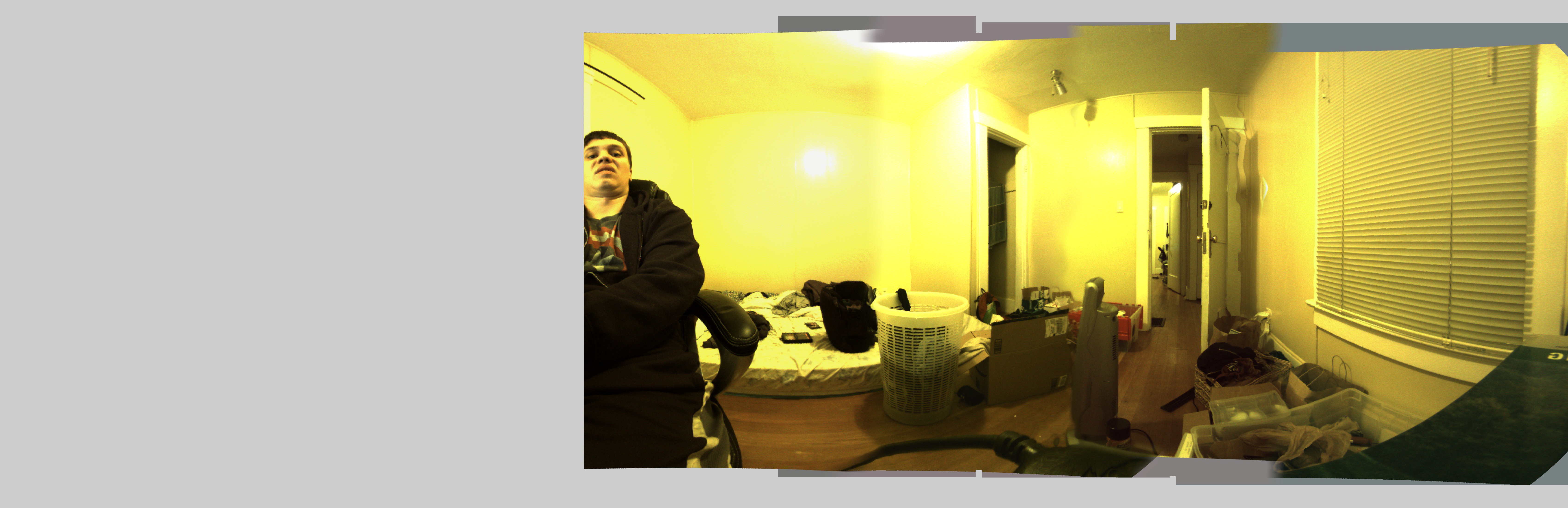
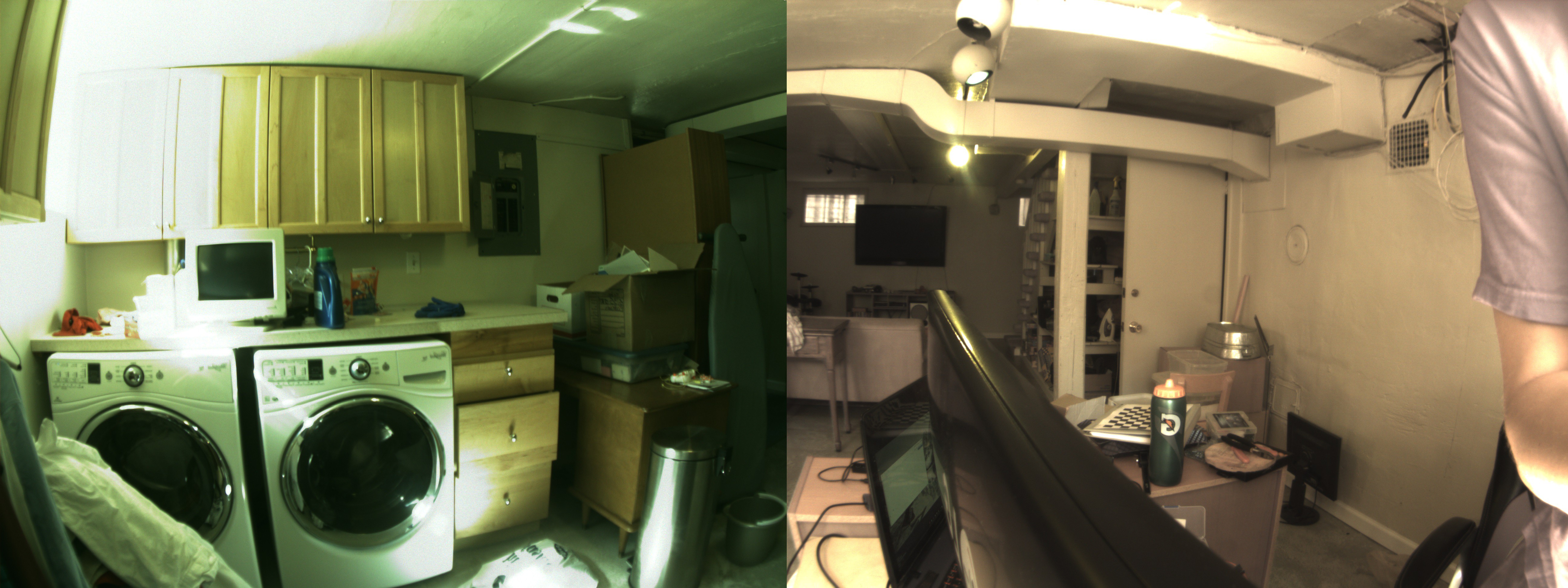
- OpenCV performs fisheye correction, stitching, and writes compressed images to MicroSD
The OV5642 module supports a variety of output formats, including JPEG compression. For still photos, I intend to set the camera modules to output raw RGB data for easy manipulation with OpenCV. For video, JPEG compression will likely be necessary.


 Adam Taylor
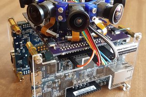
 alex
alex
 Human Controller
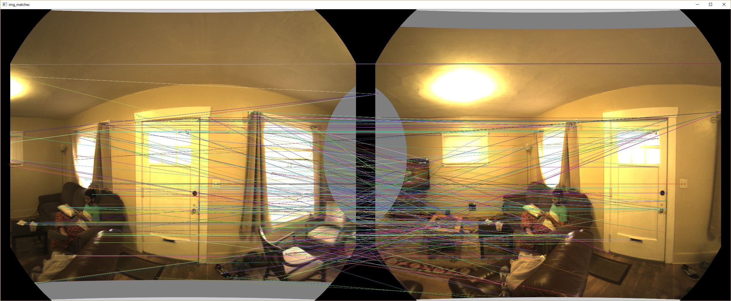
By any chance would you be willing to provide some example code for what you did with optical flow stitching?
Hugin is well-established as the go-to FOSS panorama stitcher, but it doesn't handle parallax very well. Implementing optical flow remapping as part of its pipeline would make it MUCH better for handling the output of your project AND all of the other 360 cameras out there on the market nowadays.