 mircemk
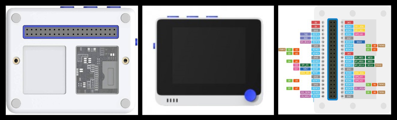
It runs at 120MHz , 4MB External Flash and 192KB RAM. The Wio Terminal itself is equipped with a 2.4” LCD Screen, onboard IMU (Acceleromete, Microphone, Buzzer, microSD card slot, Light sensor, and Infrared Emitter. Also it have three buttons, one five way switch (joystick), and reset switch. It supports both Bluetooth and Wi-Fi providing backbone for IoT projects. There is also a 40-pin connector on the back that connects external components and modules.
First I will show you how to connect and install this small but powerful device on Arduino IDE, as well as the basic steps on how to upload a program to it. I hope most readers already have some experience With Arduino, so I will explain this steps briefly.
1. We need to install Arduino IDE software
2. Click on File - Preferences, and copy below url to Additional Boards ManagerURLs:
https://files.seeedstudio.com/arduino/package_seeeduino_boards_index.json
3. Click on Tools - Board - Board Manager and Search Wio Terminal in the Boards Manager.
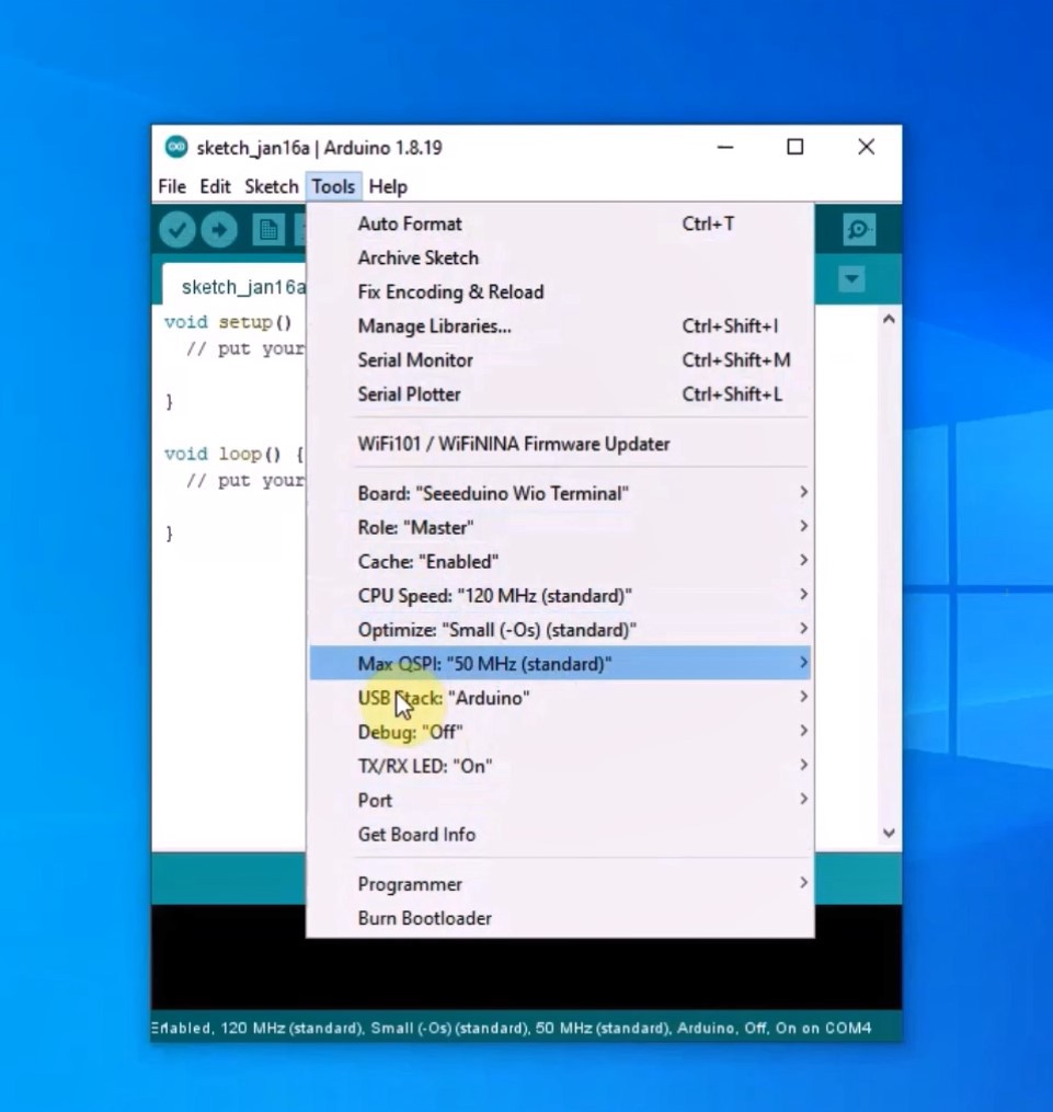
4. Now in the Tools - Board menu select the Wio Terminal. We can now upload a sketch.
This time I will describe a simple way to turn this device into a small two-channel oscilloscope. An oscilloscope is a highly useful electronic test instrument used for visualizing and analyzing electrical signals over time. It provides a graphical representation of electrical waveforms, making it a crucial tool for engineers, technicians, and scientists working with electronic circuits and systems.
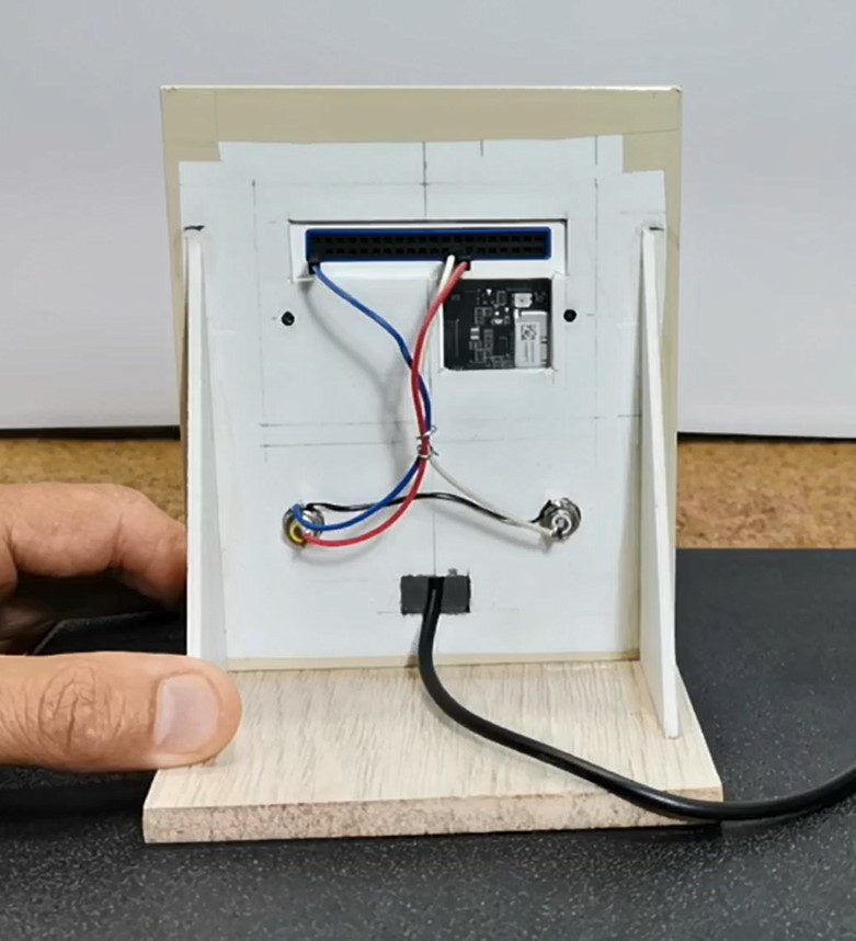
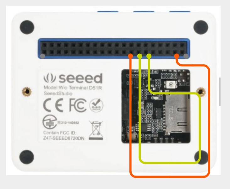
The original firmware was developed for the PIC 24 microcontroller with the built-in high-speed ADC, and the LCD display with a touch panel and can be operated by touching the screen. This is ported version for Woio Terminal, and now the device is controlled through the built-in buttons. The firmware is downloaded from the goji2100 blog , and is in .bin format. Otherwise, the device is extremely simple to make, and in addition to the Vio Terminal, we only need two more connectors for the input signal, specifically I used RCA type connectors. Channel 1 is connected to pin 13 (A0, BCM27) and channel 2 to pin 15 (A1, BCM22) of Vio Terminal, and ground.
Now I will describe the installation method because it is a bit unusual. For this purpose, we need to download the ExtFlashLoader library from the given link.
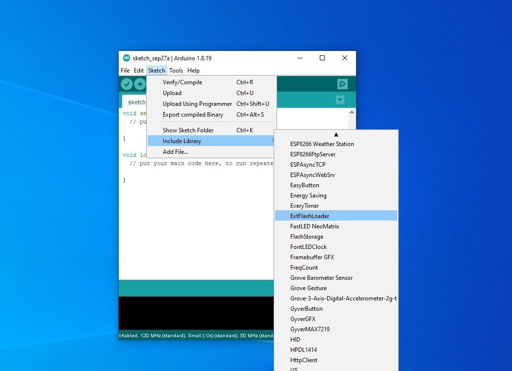
Then we put a FAT32 formatted micro SD card in the Wio Terminal in which we need to open a folder named "apps" and in that folder we put the given firmware files. Next, we need to install the "ExtFlashLoader" library, and in Arduino IDE, in Examples we need to open the "WriteSampleMenu" sketch. Now we need to install this sketch on Vio Terminal in the way I described earlier in the video.

That completes the installation and we need to start the program. This is done by holding down the A button and restarting the terminal, and then releasing the button. Now the scope is up and running and we can start testing.
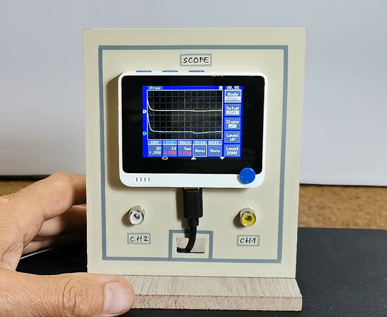
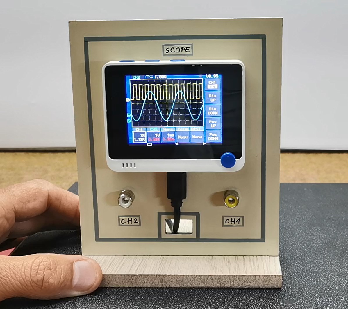
The yellow line is channel 1 and the blue line is channel 2. For the sine signal source I will use my old tone generator, and for the other shapes I will use the signal generator contained in my FNIRSI scope.
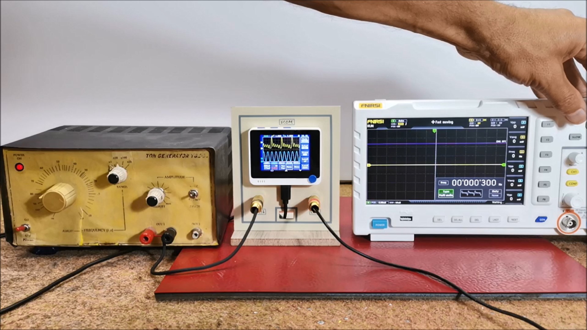
The signal amplitude of FNIRSI generator is slightly higher than 3.3 V, so the signal is slightly distorted on the lower side, and It is necessary to put a potentiometer or voltage divider at the output of the generator.
The firmware also contains a source of sine and square signals on pins 3 (BCM2) and 11 (BCM17), so if we connect the inputs to these pins, we get corresponding curves on the screen for both channels without using an external signal source. This is a particularly useful option when using the scope for educational purposes.
And finally, a short conclusion: Wio Terminal ADC is not very fast, so this device has almost no practical use, but it is therefore simple, inexpensive, and very good for studying the way this type of instrument...
Read more »
 Lauri Pirttiaho
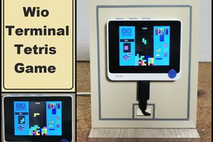
Great doc. I have a Wio Terminal sitting idle I'd like to try this with. Thank you!
When you say "not fast," can you be more specific, please? How slow is it?