 Lauri Pirttiaho
ABAX RFID 1 appears to be now and obsolete device, which is why there may be quite a number of those floating around, ending up on hacker's desks. The design has an interesting "flaw" seen sometimes in battery powered devices, the two batteries connected in parallel. That eventually seems to guarantee, that once batteries begin to age, they also begin to use energy to balance their output voltage differences due to different internal resistances, and so devices like these may end up in e-waste earlier than expected. So if you come up with one, it is probably because its soldered-in batteries are empty: recycle the batteries properly and then recycle the PCB in your favorite RFID and/or ISM (or 70 cm ham band) radio project. The schematic here will help you.
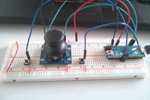
The microcontroller-on-board, ATmega328P has a plenty of memory and excellent support for SW development due to being the same as the chip on the megapopular Arduino UNO. In fact, it is not very hard to use this board as an Arduino device.
Often when one gets a decade old board like this at hand, its components are already obsolete. Not with this. All of the four chips are still available in large quantities from retailers, like Mouser and DigiKey . That means that all of the documentation is also fully available from the manufacturers, which makes SW development much easier, compared to a device for which no documentation is available and you have to reverse-engineer the SW interfaces from the firmware, if you happen to get it out from the device. In the case of this device, it appears there was no protection enabled in this 2015 manufactured device I had at hand. From disassembly it appears to be a typical main loop event handler written in C. No reason to study further as all needed information is easier to read from the datasheets than digging from the disassembly.
The ISM radio is TI CC1101, for which all information can be found in its product page: https://www.ti.com/product/CC1101. There you can find a plenty of information including source codes, and if you want to choose the easy way, there is an Arduino library avalable: https://www.arduino.cc/reference/en/libraries/smartrc-cc1101-driver-lib/. The radio is controlled via the SPI interface of the '328P. The chip select is pin PB0. Two general IO pins are also connected to the '328P, GDO0 to PB1/PCINT1, which has a handler in FW, so this is probably a receive interrupt, and GDO2 to ADC6, which is a bit odd, as the GDOs are digital outputs, but maybe that is because the designer ran out of digital pins and decided to use one of the analog pins for digital input. The other analog input of '328P, ADC7, is for measuring the battery voltage.
The 13.65 MHz NXP RFID, a Mifare radio PN512, is also controlled via SPI, with chip select PD6. Its full documentation is in https://www.nxp.com/products/rfid-nfc/nfc-hf/nfc-readers/standard-nfc-frontend:PN512. Also there you can find also SW libraries, so writing own applications should not be that hard, and for this there is also an Arduino library available: https://www.arduino.cc/reference/en/libraries/mfrc522_pn512/.
The third radio, Melexis MLX90109 for 125 kHz RFIDs, is a simpler device, is SW-controlled via pins PC0-PC5. The pin PC4 is its dedicated power switch control and reception is via SW bit-banging. The documentation is available from Melexis, https://www.melexis.com/en/product/MLX90109/125kHz-RFID-Transceiver#DocumentsSection.
The battery switching is based on an array of high-side PMOS switch transistors, DMP1045UQ. Two of the switches are for LEDs and one for the buzzer. One is for the 15 kHz RFID and then one acts as the main switch, controlled by the three buttons (of which two are in parallel to handle the potentially erratic hinged-cover pressing detection) and from the microcontroller via one BC817 transistor. The diode array is there to make the buttons to act both as the main power switch activators and as input buttons to the microcontroller.
 Arky
Arky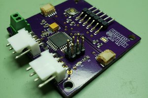
 Andrey Ovcharov
 Sagar 001