 Martijn Schouten
Multi-toolhead FDM is becoming more and more mainstream. First there was the E3D toolchanger and the Diabase H-series and recently Prusa has started shipping their Prusa XL. With the increase in increase in the number of toolheads, the complexity and functionality of the objects that can be printed is increasing. However, calibrating the tool offsets is also getting more and more complicated.
However, to calibrate XY offsets all manufacturers use calibration patterns (e.g. UltiMaker and Prusa). Calibration using these patterns is not very accurate and it also is very tedious. Especially if you have 5 toolhead. To automate the XY offset calibration several projects have tried vision based solutions such as the ones described here and here.
But optical calibration is not known for being very reliable, and can easily break in case the nozzles are a bit dirty. To solve this issue I have worked on developing an inductive calibration method. Inductive methods have the big advantage that they can look through any non-conductive materials. For this reason, the same measurement principle is also used in metal detectors.
To calibrate the XY offsets of the printer this tiny metal detector is placed on the 3D printer bed. The printer then moves its nozzles over the metal detector one by one. The signal that the metal detector measures will be maximum when the nozzle is exactly above the metal detector. By comparing the nozzle locations for which the signal was maximum with each other the tool offsets can be worked out. To get both the x and the y offsets the nozzle has to be moved over the coil in both the x and the y direction.
The module is connected to a PC using USB. The same PC is also connected to the printer using USB. The calibration is done by running a Python script. This Python script moves the printer and then reads out the inductance and then moves the printer a bit further again and reads out the inductance again and so on. This allows the script to determine the inductance as a function of the nozzle position.
After having moved each nozzle over the coil it determines the peaks in the inductance graphs that it has measured. To do this with maximum accuracy it uses a little trick. Instead of just detecting the maximum, it first fits a function called a symmetric polynomial (=polynomial with only even powers) to the graph and then uses that fit to compute the maximum instead. It also moved back and forth to compensate for any temperature drift due to the nozzle heating up the coil. If you want try out this calibration method for yourself, the GUI can be downloaded from the releases page of this git.
The tiny metal detector consisted of a tiny SMD coil (LQW2UAS4R7J00) soldered on a PCB that allows measuring its induction. The coil is soldered under a 90-degree angle so that the opening in the coil is on the top. This way it is more sensitive to the approaching nozzle. The PCB is an inductance to digital converter evaluation module from Texas Instruments named LDC1101EVM. This PCB does exactly what I wanted it to do. But it is pretty expensive and for making this a product it would be better to integrate a LDC1101 and an Arduino on a PCB and then change printer firmware so that it can directly communicate with this Arduino. I don't have time for this currently (and I don't have access to a multi-material printer anymore). But if you are interested in developing this I would be happy to provide support.
Some of you with an interest in physics might be wondering, why does the inductance sometimes go up and sometimes go down? This is because some nozzles are steel and therefore ferromagnetic and some are made of brass and only conductive. For the ferromagnetic nozzles the inductance increases, just like putting an iron core in a coil increases it's inductance. For the conductive nozzles, the process is more complicated. In this case, the current in the coil induces a current in the nozzle. That current in the...
Read more »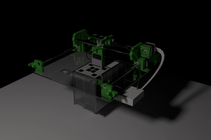
 megahercas6
 TTN
TTN
 advancer01